UNIVERSITÁ DEGLI STUDI DI CATANIA
FACOLTÁ DI INGEGNERIADIP ART IMENTO D I INGEGNER IA ELE TTR ICA, ELETTR ON ICA E DEI S ISTEM I
Dottorato di Ricerca in Ingegneria Elettronica, Automatica
e del Controllo dei Sistemi Complessi
_______________________________
Cristoforo Camerano
Technological platforms for immaterial art
Ph.D. Thesis
Tutor: Prof. L. Fortuna
Coordinator: Prof. L. Fortuna
________________________________
ANNO 2010
Contents
Chapter I Introduction...Pa g.2 Chapter II Chaotic robots:Interac tion be tw een art a nd technolog y...P ag.6
Chapter III
Chaotic robots and kinetic art...Pag.19
Chapter IV
Synchronization of chaotic robots...Pa g.28
Chapter V
From kinetic art to immaterial art through synchronization
of chaotic robots...Pag.34
Chapter VI
Mirror neurons robots: Learning synchronization...Pag.42
Chapter VII
Mirror neurons robots and immaterial art...Pa g.52
Concluding remarks...Pa g.62 References...Pa g.64
Chapter I
Introduction.
The “Dipartimento di Ingegneria Elettrica, Elettronica e dei Sistemi” (DIEES) at the University of Catania is involved in several research projects focused on the study and development of Interactive Technological Platforms for the control of multitasking robots and for the development of the process of interaction between human and robots. These robotic platforms represent nowadays a powerful instrument able to augment the perception capabilities offered by the adoption of classical ground robots.
Also the DIEES department of University of Catania is involved in different projects for the development of Interactive Tehcnological Platforms used for the creation of immaterial art, through the use of systems of interaction between users and robots able to create patterns of light and able to generate a sets of strange attractors.
This work presents a project following a path from kinetic art to immaterial art through synchronization of dynamical systems. Two or several robots driven by a chaotic system follow irregular trajectories and their motions are coordinated. Then thanks to a pattern of lights the robots generate interesting images and patterns. In this way the viewer-user is invited to take an active role in the creation of this kind of “immaterial art”.
Artists and engineers already conceived robots that are in communication with the spectator through a simple interface.
Furthermore robots and other technological systems are used to create artwork.
For example at the “Korean Pavilion” of “International Shanghai World Expo’ 2010 (China)” during the event “Better city, Better life 2010”, an event-project that shows to the spectator how is possible interact with technology in order to create art, the children are invited in a special technological museum and they are involved in a process of creation of visual art through different interactive mechatronics platforms.
Fig.i1. Interactive Platform at “Korea Pavillion of International Shanghai World Expo’ 2010 (China)” during the event “Better city, Better life 2010”.
The present work is organized as follow into seven chapters that cover R&D conducted at the DIEES department on several aspects related to the topic of Interactive Platforms for the creation of immaterial art.
Chapter II
Chaotic robots: Interaction between a rt and techno lo gy.
The chapter sho ws the p rocess of interaction between art and technolo gy.
Chapter III
Chaotic robots and kinetic art.
The chapter describes in details the realized platform and the obtained results.
Chapter IV
Synchronization of chaotic robots.
The process of synchronization of chaotic robots is here described. The role of chaotic synchronization in the generation of the kinematics trajectory shows the discovering of new aesthetic features of the motion in mechanical control systems.
Chapter V
From kinetic art to immaterial art through synchronization of chaotic robots.
The realized platform for the synchronization of two robots is here described. The process of creation of art through the interaction between user and robot is also explained. A lot of results are shown in this chapter.
Chapter VI
Mirror neurons robots: Learning synchronization.
The research takes inspiration from the study of the applications on robotics of Mirror Neurons as principles of imitation and learning of movement. In this chapter the principles of the learning synchronization between two robots are described.
Chapter VII
Mirror neurons robots and immaterial art.
The realized platform for the creation of immaterial art throu gh the in tera ction between user and “m irro r ne uron robots” is here de scribed.
Chapter II
Chaotic robots: Interaction between art and
technology.
2.1 The state of the art.
The interaction between art and technology, especially computing technology, is an increasing trend in the recent days. The context of this intersection is growing in numbers, size and aspects each year. The number of artists participating in multimedia software or games development projects is continuously increasing and so is the number of software engineers participating in art projects like interactive art installations.
Many artists for centuries have expressed through pictures and sculptures their visions of the past, present and future. Some contemporary artists decide to use technology like a bridge between man and machine [1].
In my thesis’ project this creative process takes part as the result of the interaction of robots and the human regulating some of the parameters of the robot behaviours: self-organization plays a fundamental role, since the man does not command the robots but interacts with them.
This work presents a project following a path from kinetic art to immaterial art through the control and observation of dynamical
systems. Diffirent robots driven by a chaotic system follow irregular trajectories and their motions are coordinated. Thanks to patterns of L e d lights the robots generate interesting images. The generation of a sets of strange attractors is a way to create art through robotics, sensors, computing, engineering, lasers, and countless other tools and devices. Furthermore an interactive platform is designed to actively involve the spectator in the creative process. The viewer is thus invited to take an active role in the creation of the piece of art. In particular in our experiments the interactive platform consists of a pc station and a Bluetooth controller. The spectator is able to change the parameters of the chaotic trajectories followed by the robots.
An important aspect of this work is to outline a possible relation between emergent patterns created by robot movements, the robots themselves and art. Moreover, the aim is to relate a spectator with the two (or more) robots used, that are just the way of creating art.
Some engineers and artists have already conceived robots that are in communication with the spectator through a simple interface. Furthermore, these robots are able to create artwork. For instance, Leonel Moura has created painting robots that are equipped with environmental awareness and a small brain that runs algorithms based on simple rules [2].
2.2 The environment of experiments.
The results of the research o f t h i s t h e s i s are related to the behavior of cooperative robots that have been originally developed for inspection and scanning tasks.
Let us consider the problem of analyzing an environment. Some measurements are needed to perform which we need to use different sensors. The scenario where the measurements must be taken is a three-dimensional space with spatial coordinates (x, y, z) where equipments must be dynamically located in order to perform different types of investigations and where the kinematism assures
the realization of a congruent set of detections.
Each robots is placed in the x − y plane where their trajectories are controlled in order to avoid collisions among them.
Moreover, the robot arms allow us to scan the space in the z direction. Let us consider n sets si (with i = 1, 2, . . . , n) of robots, each of one working in the general space area i. Each set of robots is made by a cluster of m robots, where each robot is labelled as cj (with j = 1, 2, . . . , m). Within a cluster, each robot is different by the others for its mechanical structure, sensor equipments, and so on. The task of each robot in the cluster is to provide specific functions and to explore the environment in different points in order to get complete specific information.
Randomized trajectories are generated for each robot and a random search algorithm is used to improve the detection performance of the clusters. In particular, instead of using randomized positions a strategy based on chaos allocation has been conceived. In this way, even if a randomized motion is performed, the robots in the cluster can be synchronized each other to coordinate their behavior.
The use of synchronization of chaotic systems has been widely studied for different applications, but the adoption of synchronization of chaos driven robots in the first part of the thesis has not been widely investigated. The use of synchronized clusters of robots is adopted in this work in order to implement coordination of robot trajectories both inside each cluster and among the various clusters (see Chapter IV).
Summarizing a number of mobile agents has been realized by using different kinematic structures. The LEGO system allowed us to easily implement them. In several points of each robot a set of light markers are placed to monitor the robot trajectories.
2.3 The used robots.
In the first part of the work are used four robots. The robots are different each other and have different mechanisms of locomotion. • Robot 1. Robot 1 is a four-wheeled robot. A scheme of the robot is shown in Fig. 1 and Fig 1.a.
• Robot 2. Robot 2 is a four-wheeled robot with a robotic arm conceived to be equipped with sensors for monitoring. A scheme of the r o b o t is shown in Fig. 2 and Fig 2.a.
• Robot 3. Robot 3 has a locomotion mechanisms based on the crawling of two mobile parts connected by gears actuated by DC motors. A scheme of the r o b o t is shown in Fig. 3 and Fig 3.a.
• Robot 4. Robot 4 is a six-legged robot. A scheme of the r o b o t is shown in Fig. 4 and Fig 4.a.
Fig.1.a Robot 1
Fig.2.a Robot 2
Fig.3.a Robot 3
Fig.4.a Robot 4
2.4 Control Platform and Control Law.
The aims of this work is to design an interactive platform that establish a communication between the robots and the spectator. The experiments we are presenting are related to the behaviour of four robots used to create art. The d e s i g n e d robots can move in all directions within an arena of 3.5 m deep and 4 m wide. The h eigh t of the a rena wa lls is 40 cm . The scenario is totally dark, the floor and the wall colour is black and initially the light is turned off, therefore the spectator can see just the effects produced by the luminous pattern mounted on each robot. A camera is located in a strategic point to take pictures of the whole arena every 10, 15 or 20 seconds. Then, either photos with long exposure times or videos of the robot motions were taken. In the latter case the video is then postprocessed in order to have the complete trajectory of the robot.
with markers (different Leds were equipped on each robot as w i l l b e explained in Paragraph 3.3).
The interaction between the user and the robots occurs at a simple interface which includes for our experiments a pc station and a Bluetooth station controller.
We can distinguish the virtual environment and the real environment. If the light o n t h e r o b o t s is turned off, the viewer just see some light effects that change continually and he doesn’t know what are the causes that generate the images. This is the virtual environment. Instead the real environment is noticed by the viewer just when he decide to turn on the light. The spectator can see the robots that generate strange attractors through a system of different Led’s light. The idea behind trajectory control is to have irregular (random) trajectories that can be useful in tasks such as exploration, construction of a map of the environment or measurement sampling. Instead of generating such trajectories starting from random number generators, the idea is to use chaos to drive the robots and to study the interaction between them (Chapter III), such that the concept of chaotic synchronization can be used to coordinate the motion of two (or more) robots preserving the irregularity of their trajectories (Chapter IV).
The scenario and the electronic components used to design the interactive platform are illustrated in Fig.5. The user can change some parameters about the trajectory of the robots through a pc station and a Bluetooth controller and at the same time a camera takes the pictures of the robots while moving and interact between themselves.
Fig.5. Interactive Control Robot’s Platform
In this section the control law of the robots is discussed. We first describe the kinematic model of the robots used and then the i m p l e m e m n t e d control law.
As shown in paragraph 2.3 in our experiments we used f our different robots which differ for the mechanical design and the actuation strategy. The different capabilities and structures allow the robots to fulfil different requirements so that, for instance, they can adapt to different terrains or perform different tasks. However, at a high level we can describe the robot kinematics under a common framework. Infact, for all the robots the basic mechanism is a differential drive system, where two actuated wheels with the axle placed at the center of the robot are used.
This basic mechanism is implemented in different ways in the different robots used in this work. In particular, referring to the robots of Fig. 1 and Fig. 2 four actuated wheels are used; the two wheels of each side of the robot are actuated in the same manner so that an effective differential drive system is obtained. In the case
= = = vR +vL vR +vL dx dy
of the robot of Fig. 4 which makes use of legs, the description of robot kinematics in terms of a differential drive system should be considered an abstraction at a higher level, where the details of the steering movements are not taken into account in the definition of the control law which only focus on the steering angle and the overall forward motion.
In the differential drive model, the robot overall motion depends on the velocity of its center point (the midpoint of the axle). This velocity is simply the average of that for the two wheels. The steering depends on the difference between the velocities of the two wheels. Let us indicate with x, y, θ the position and orientation of the robot with respect to a fixed frame of reference and with b the length of the axle, i.e., the distance between the two wheels. Under these assumptions, the differential drive model can be described by the following equations:
dθ vR −vL
dt b
dt 2 cos(θ(t)) (1) dt 2 sin(θ(t))
The robot is driven by a control law which specifies vR (t) and vL (t) at each time instant. In particular, we consider a logistic map
zk+1 = azk (1 − zk ) (2)
and, given zk , we build vR (t) and vL (t) for tk ≤ t < tk+1 by
following one of the algorithms described below. A new value of the map, zk+1 , is then computed, which allows to calculate
vR (t) and vL (t) in the next time interval [tk+1 , tk+2 [, an so on. We use a = 4 so that chaotic behavior is obtained and notice that zk can be generated with other chaotic maps or from analog chaotic systems such as the Chua’s circuit [3].
We now describe how the value of zk is used to build vR (t) and vL (t). Let us indicate with v the maximum value of the wheel velocity. Different algorithms have been used to drive the four robots in the arena:
Algorithm 1. We let the robot move in the forward direction for a
fixed amount of time, T1 = 280ms, and then turn to the left (or to the right) for T2 ∝ zk if zk ≥ 0.5 (or zk < 0.5).
Thus, we fix: vR = vL = v for tk ≤ t < T1 and vL = 0.9v, vR
= 0.1v for T1 ≤ t < T1 + T2 if zk ≥ 0.5 (or vL = 0.1v, vR = 0.9v
for T1 ≤ t < T1 + T2 if zk < 0.5 in the case of right turn), where,
if zk ≥ 0.5, T2 = 3000zk (expressed in milliseconds) or, otherwise,
T2 = 5600zk (expressed in milliseconds). In the computation of T2 two different constant are used to balance the duration of left and right turns. In this case, the chaoticity of zk thus reflects in two characteristics of the robot trajectory: the sequence of left and right turns is unpredictable, and the steering angle is irregular.
Algorithm 2. This algorithm follows the same rules of the algorithm
1, but in this case the forward movement occurs for T1 = 500zk (expressed in milliseconds). Therefore, in this case the duration of the forward movement is also chaotic.
Algorithm 3. In this case the robot can perform different actions
according to the value of zk . We divide the interval of admissible values of zk (i.e., [0, 1]) into seven subintervals: F1 = [0, 0.15[, R1 = [0.15, 0.3[, L1 = [0.3, 0.45[, R2 = [0.45, 0.6[, L2 = [0.6, 0.75[, R3 = [0.75, 0.9[, and L3 = [0.9, 1]. We then associate the interval F1 with a forward movement, the intervals R1 , R2 and R3 with a right turn and the intervals L1 , L2 and L3 with left turns, so that, for instance, if zk ∈ F1 , the robot proceeds in the forward direction, while, if zk ∈ R1 , the robot turns to the right.
The actions associated to R1 , R2 and R3 differ for the values used for vR and vL , and thus for the turn angle. As an example, if zk ∈ R2 , then vR (t) = 0.1v and vL (t) = 0.6v for tk ≤ t < tk+1 ,
while if zk ∈ R3 , then vR (t) = 0.1v and vL (t) = 0.9v for tk ≤ t < tk+1. The chaoticity of zk thus reflects in an unpredictable sequence of forward, left and right turns.
Chapter III
Chaotic robots and kinetic art.
3.1 Art of chaotic robots through kinetic.
In this work the emergent behaviour of the kinematic trajectories of classes of robots will be shown and a wide family of generated strange attractors will be presented. Moreover, the role played by simple mechanical systems in generating complex strange attractors will be remarked in this thesis. The generation of strange attractors has been widely faced in the last years. The well known gallery of strange attractors of the Chua’s circuit is widely known in the literature [4], [5], [6]. Moreover, in [7] Sprott gives us a wide range of generated attractors by using numerical simulations of numerous dynamical systems. However, the wide variety of patterns based on strange attractors achieved an impressive aesthetic level such that more people worked in order to emphasize in art the impressive features of strange attractors [8] considering chaos as bridge between art and science. In this fashion in recent years (more precisely, in 2006) at the Zendai Museum of Modern Art an impressive exhibition entitled “Strange attractors: charms between art and science” has been organized. The important aspect of this work is therefore to relate emergent patterns, robots and arts. Recently, remarkable features relating arts and robots have been focalized by Mari Velonaki [9] that creates a cooperation between artists and
scientists in robotics. Moreover, in this research the robots did not create emergent patterns.
Emergent patterns are, instead, evident in the work of Ken Goldberg [10] which is well known for his research study in both the fields of robotics and art. Among his works, he conceived an industrial robot to make art and in particular to paint. In this study it has been shown as a simple kinematic chain realized by using easy mechanisms leads us to obtain complex emergent patterns.
In the last years simple mechanisms have been introduced to generate spatial patterns. In the work of Murakami Koji et al. [11] a technique of extracting important behavioural patterns from a series of observed motions has been introduced.
Moreover, the emerging properties of the cooperation among robot parts and the cooperation among classes of robots has been not dealt with in the previous study.
Robots with simple rules moving in a complex environment have been proposed by Tilden [12]. In this class of robots the interaction with the environment is fundamental for the performance of the equipments of the BEAM project.
BEAM project stands for Biology, Electronics, Aesthetics and Mechanics, where also the role of robots for aesthetics have been considered.
In this study new concepts are reported joining the multitask cooperation of different classes of robots, the use of chaos synchronization and control, the identification of simple rules that, coupled with random walk-like algorithms, lead to the emergence of spatial trajectories.
Indeed the project carried out by Frank Popper “From technological to virtual arts” aims to develop interactions among interactive new media art from its historical antecedents, emphasizing the role of new technologies like laser, olography as new tools for art [13]. The aim of this research including cooperative robots, strange attractors synchronization completes in some features the ingredients
mentioned in the Frank Popper’s idea in order to conceive robots to be integrated in virtual arts where the main topic is the spectator interaction and participation.
The emergence concepts in generating new patterns will be emphasized in this work. The study described in this thesis could be considered as a further example of serendipity, in fact starting from a random walk approach for robot cooperation emerging behaviours of kinematic chains emerged. Serendipity as one of the major components of scientific discovery itself expresses as an hidden phenomenon could be let emerge.
3.2 Trajectories of mechanical strange attractors: analysis of single robots and interaction of different robots.
Let us consider for example a 3D space where the robots scans the x − y 2D space by dividing it in given slice.
Let us consider that the robots move into a horizontal plan while performing the scanning operation in the vertical direction. Therefore, we need that a measure done at a general point (x(1) , y(1) ) of the x − y plane must be repeated in many points of each section/slice of the plan and that the measures are done at points which are aligned. The same consideration has to be done for vertical inspection.
Moreover, the interaction of robots in each cluster, even if collisions among robots are avoided, establishes regularization of the chaotic motion of the other robots in the single cluster and allows an appropriate organization of the measurement space.
The led markers are placed on the top of the front part of the robots and allow the robot trajectories to be tracked.
In the first part of the experiments we have not studied the synchronization of the logistic maps that drive the robots: it was investigated the behaviour of the robots and the interaction of themselves on the fixed arena.
is now reported. The trajectories that are shown represent a strange attractor gallery of experimental routes generated by using mechanical device synchronization. In particular, the control strategy adopted consists in emphasizing the cooperation and the randomized motion avoiding collisions among robots. Each robot follows a chaotic trajectory ruled by one of the three algorithms described in paragraph 2.4.
In order to trace the trajectories of the robots, they were equipped with markers ( l e d l i g h t s ) and the whole environment was totally obscured. Then, either photos of the trajectories with long exposure, of the robots times were taken.
The trajectories generated by a single robot are shown in Fig. 6.
In particular, in Figs. 6 and 7 the trajectories generated by robot 1 are shown, while Fig. 8 refers to trajectories generated by robot 4. The figures show the robot trajectories tracked through the markers placed in the robots. More in details, in Fig. 6(a) robot 1 is equipped with a blue led (led 1) and a yellow led (led 2), while in Figs. 6(b)-6(d) a red led is used for led 1. Furthermore, Figs. 6(b) and 6(d) refer to a top view, while Fig. 6(c) to a front view.
The same robot has been used in the experiments shown in Fig. 7, equipped with a red led (led 1) and a yellow led (led 2) in Figs. 7(b) and 7(c) and with a blue led (led 1) and a red led (led 2) in Figs. 7(a), 7(d)-7(f ). We notice that the trajectories generated by robot 1 and shown in Figs. 7(a)-7(e) are similar to the phase-plane projections of a well-known chaotic attractor, the so-called n-double scroll [14].
The pictures refers to robot 2, equipped with two blue leds (led 1 and 2) a r e s h o w n in Figs. 8(a)-8(d). In this series of figures the red traces are due to the optic fiber which is switched on. In Figs. 8(e)-8(f ) the optic fiber is switched off and a blue led (led 1) and a green Led (led 2) are used. Even in this case, the trajectories shown are the combination of the chaotic motion of the robot arm and of the robot itself.
The following series of images are generated by using two of the four robots. In particular, Figs. 9 and 10 refer to robot 1 and robot 2. The figures differ for the control laws adopted and for the choice of the markers. Markers are always placed as shown in Figs. 1 and 2, but have different colors. In particular, in Figs. 9(a) and 9(b) robot 1 is equipped with a blue led 1 and a yellow led 2, while in Figs. 9(c) and 9(d) it is equipped with a red led 1 and a yellow led 2.
In Fig. 9 robot 2 is equipped with a red led 1 and a blue led 2, while in Fig. 10 it is equipped with a green led 1 and a blue led 2.
In the same figure (Fig. 10) robot 1 is equipped with a red led 1 and a yellow led 2. The trajectories obtained in Figs. 9 and 10 show the interaction of the two robots, each one controlled by a chaotic control law.
Fig.10. Gallery of pictures obtained with the Robot 1 and Robot 2 (see paragraph 2.3)
The images shown in Fig. 11, refer to the simultaneous motion of the four robots in the same arena. Each of the robot is controlled by one of the algorithms described in Section 2.4 and thus follows a chaotic trajectory. Furthermore, we apply the same control law to each motor used in the robots. For instance, in the case of robot 2, this means that the motor controlling the arm is also driven by a chaotic law.
The final picture, where the movements of the robots are tracked through the trajectories of their led markers, thus, represents the combination of the movements of all the robots and their moving equipments. In particular, in Fig. 11, were used the following markers: for robot 1, led 1 is red, led 2 is green; for robot 2, led 1 is
red, led 2 is blue; for robot 3, led 1 is red, led 2 is green; for robot 4, led 1 is yellow, led 2 is red, led 3 is green. The marker position adopted is that shown in Figs. 1-4, so that, for instance, led 1 of robot 1 allows the trajectory of the robot to be tracked, while led 2 allows the position of the robot arm to be tracked.
Chapter IV
Synchronization of chaotic robots.
4.1 The platform and the mechanical structure of the robots.
In this chapter will be described how two twin robots driven by a chaotic system follow irregular trajectories and the coordination of their motions. Thanks to a pattern of lights the robots generate interesting images. The experiments we are presenting are related to the behaviour of two twin robots that are used to create art. Moreover, the synchronization between the trajectories followed by two robots can be an initial point to coordinate more robots in order to investigate more interesting luminous paths. A red Led light and a green Led one differentiate a robot from the other, called respectively the ‘ master’ and the ‘ slave’. The robots can move in all directions within an arena of 190 cm deep and 245 cm wide. The scenario is totally dark, the floor and the wall colour is black and initially the light is turned off, therefore the spectator can see just the effects produced by a luminous pattern mounted on each robot. A camera is located in a strategic point of the arena to take pictures of the whole arena every 10, 15 or 20 seconds.
The interaction between the user and the robots occurs even in this case is an interface which includes for our experiments a computer station and a joystick BT controller.
environment. If the light o f t h e r o b o t s is turned off, the viewer just see some light effects that change continually and he doesn’t know what are the causes that generate the images. This is the virtual environment. Instead the real environment is noticed by the viewer just when he decide to turn on the light. The spectator can see two coordinated robots that generate strange attractors through a computing led pattern and a camera which send to a slide projector the pictures that it takes about the luminous paths.
The scenario and the electronic components used to design the interactive platform are illustrated in Fig.12. The user can change some parameters about the trajectory of the robots through a pc station and a Bluetooth controller, at the same time a camera takes the pictures of the twin robots while moving. The images acquired are sent to a secondary computer which is connected to a slide projector.
For their easy of implementation and reconfigurability, the LEGO MINDSTORMS robotic kit has been chosen to implement the kinematic structure of the robots [15].
In this experiment are used two twin robots. The robot basic structure is the classical differential drive consisting of two actuated wheels and two smaller passive caster wheels, whose function is to keep the robot statically balanced. The caster wheel has two axes of rotation, but the vertical axis does not pass through the centre of the wheel, so this type of wheels swivel automatically, rapidly aligning with the direction of motion of the chassis. The differential drive design with two passive wheels cannot have the driving wheels in the middle of the robot, for stability reason. The two passive wheels have been introduced to provide a supporting point for static balance without affecting the mobility of the base. When robot turns on the spot, it will rotate about the off-centre midpoint between the two driven wheels. The robot overall motion depends on the average of velocity of the two wheels. The steering depends on the difference between the velocities of the two wheels.
Fig.12. Interactive platform used for the synchronization of the two robots
Let us indicate with VMA and VMB the velocities of the two motors (MA and MB). The following equations describe the differential drive model: d
θ
=VMA − VMB dt c (3) dx =VMA − VMB cos(θ (t )) (4) dt 2 dy =VMA − VMB sin(θ (t )) (5) dt 2where c is the distance between the two actuated wheels. We have indicated with x , y and ө the position and the orientation of the robot
Moreover, the robot is equipped with an arm on which the electronic device that generate time varying light patterns is mounted. The arm is actuated by a third motor, which turns round very fast. The electronic device mounted on the arm consists of an array of sixteen RGB led and a controller driven autonomously from the robot motion control. Several parameters such as colours, brightness, frequency and intermittence of lights can be controlled, thus generating different luminous patterns. For the purpose of obstacle avoidance, two ultrasonic sensors are placed in front and behind the chassis.
The lateral and frontal schemes of the robots are shown in Fig.13 (a, b, c).
4.2 The control law.
In this section, is described how the control law is implemented. In the experiments for the twin robots the basic mechanism is a differential drive system consisting of two actuated wheels and two rear passive wheels. The two motors can be controlled in two different directions, called forward and reverse. If MA and MB are both in forward mode and VMA=VMB the robot goes in forward direction. If MA is controlled in forward mode and MB is off the robot turns left. If MA is turned off and MB is in forward mode the robot turns right. In the last two cases the steering depends on the velocity of the motor that is turned on.
The robot is driven by a chaotic control law which specifies VA and VB at each time instant. In particular a logistic map is used.
The equation of the logistic map is:
z k +1 = az k (1 − zk ) (6)
Given zk we build VA(t) and VB(t) for tk ≤ t ≤ t k 1 . A new value of the
map, z k 1 is then computed, which allows to calculate VA(t) and VB(t) in the next time interval tk 1 ≤ t ≤ t k 2 , and so on. The algorithm followed by the robot master is now described. According to the value of
zk the robot can perform different actions. The interval of admissible
value of zk is [0,1] and we fixed a constant value k=100. If 0≤ zk <0.1
MA and MB are in reverse mode with the same velocity VMA=VMB= (k zk +60), thus the robot drives straight backward. If 0.1≤ zk <0.4
MA and MB are in forward mode with the same velocity VMA=VMB= (k
zk +60), thus the robot drives straight forward. If 0.4≤ zk <0.7 MA
is in forward mode and its velocity is VMA=(k zk +30) while MB is turned off, in this case the robot turn left. If 0.7≤ zk <1 MB is in forward
the robot turns right.
The sequence of left and right turns thus depends on the chaoticity of zk (VMA and VMB ∞ zk ), leading to an unpredictable trajectory.
The twin robots are coordinated following the idea discussed in [16]: the chaotic synchronization is used to achieve t h e robot coordination. According to this strategy, the two robot trajectories are coordinated thanks to the synchronization between the two logistic maps controlling the two robots. When the robot master starts its motions, it sends a start message to the slave one which moves in the same direction. The robots conveys through Bluetooth technology. If the master hits an obstacle, the robot avoids it and, sending messages to the other robot, allows that the slave robot follows a similar behaviour. In Fig. 14 is shown some frames of the realized interactive platform.
Chapter V
From kinetic art to immaterial art through
synchronization of chaotic robots.
5.1 Generation of mechanical strange attractors from
synchronization of chaotic robots.
The two coordinated robots follow a chaotic trajectory ruled by the algorithm described in section 4.2. The synchronized chaotic systems generate trajectories and thus images following an ideal path from kinetic art to immaterial art. In the definition of kinetic art the term kinetic refers to an artwork that are in motion or have parts that move. The motion of the work can be provided in many ways: mechanically; by utilising natural phenomena such as wind; or by relying on the spectator to provide the motion. In this work two twin robots that move following a chaotic law have been used. The term immaterial refers to the lack of material piece such as in traditional art: sculptures, paintings, buildings.
The first artist that conceive the ephemeral immaterial art was Yves Klein. His aim was to let the viewer to perceive and understand an abstract idea. Thus, Klein’s void is an area where the spectator can perceive the reality beyond the representation. Moreover, he thought that all colours arouse specific associative ideas, psychologically material or tangible, while blue suggests at most the sea and the sky, and they are in actual visible nature what is most abstract. For this
reason he created the International Klein Blue, that for him has no dimensions [17].
In this work the spectator perceives just the alternation of luminous patterns but he cannot see the synchronized robots which constitute the background for the generation of an always dynamically changing artwork that is the result of the interaction between the viewer itself and the robots.
The viewer can perceive the reality in different ways, since at first it is not aware of the ways in which the luminous patterns are generated, and, in a second step, when the environment lights are turned on, it can become aware of the background of the artwork and have a different perception of the trajectories generated. The robot master and the robot slave produce interesting images that slide quickly thanks to a camera that takes pictures of them. Every image is unique, it is improbable to obtain the same picture for two times. Several variables change continually in every click and make each image different from the others, for example: the start point of the master with respect to the slave; the intermittence and the colour of the luminous pattern; the presence of obstacle and the trajectory followed during the data capture process; the exposure time of the camera lens.
A variety of trajectories observed during the motion of the twin robots are now reported.
The first series of images, shown in Fig. 15, refers to the motion of the robots during a time interval of 10 seconds. In the second and third series of pictures, Fig. 16 and Fig. 17, the exposure time of the camera lens is set to 15 and 20 seconds respectively.
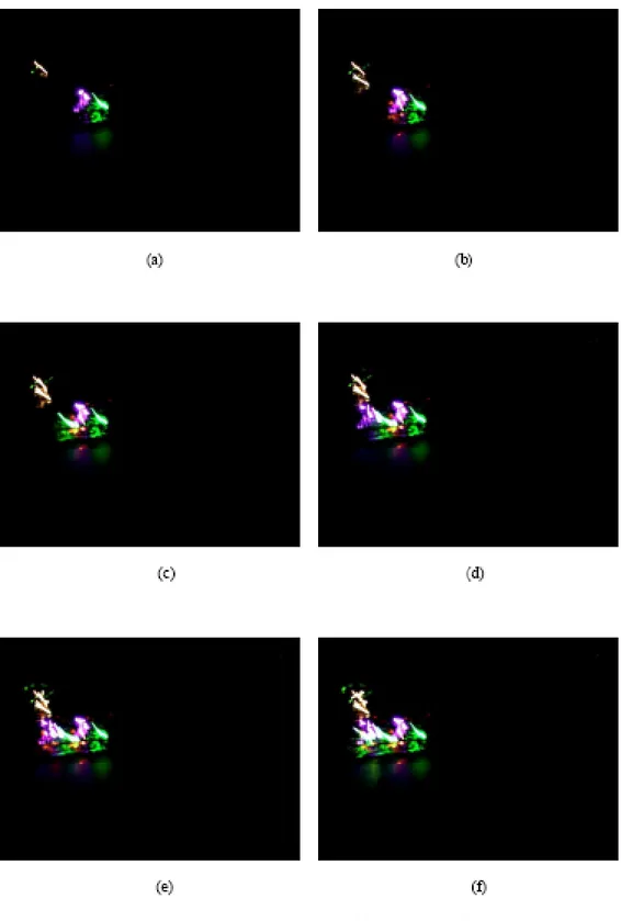
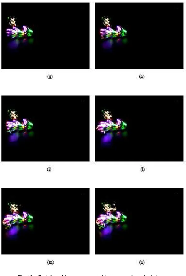
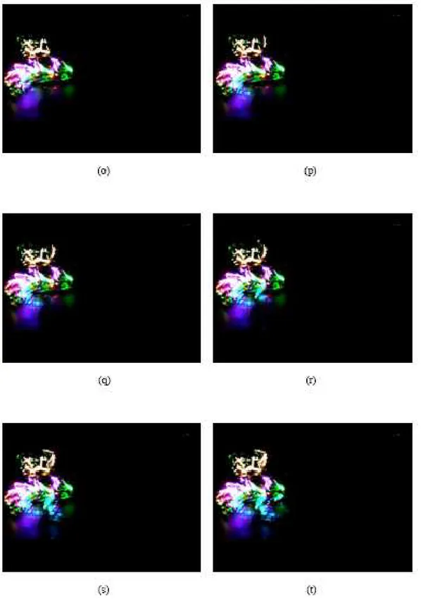
The series of images, shown in Fig. 18, refer to the evolution of the trajectory that the camera acquire every 0.25s. Fig. 18(b) shows the path of light during 0.50s; Fig. 18(c) shows the path during 0.75s and so on.
Fig.15. Gallery of pictures obtained with the two robots described in Sec.4.2. In particular, the time exposure of the camera lens is 10 seconds.
Fig.16 Gallery of pictures obtained with the two robots described in Sec.4.2. In particular, the time exposure of the camera lens is 15 seconds.
Fig.17 Gallery of pictures obtained with the two robots described in Sec.4.2. In particular, the time exposure of the camera lens is 20 seconds.
The frames generated by the coordination of the twin robots for a variable value of the time t, are now presented in Fig.18 (a,b,c,d,e,f,g,h,i,l,m,n,o,p,q,r,s,t).
Fig. 18. Evolution of patterns generated by two coordinated robots during: (a) 0.25s ( 0<t<0.25); (b) 0.50s (0<t<0.50); (c) 0.75s (0<t<0.75); (d) 1s (0<t<1); (e) 1.25s (0<t<1.25); (f) 1.50s (0<t<1.50); (g)1.75s (0<t<1.75);(h)2s (0<t<2); (i) 2.25s (0<t<2.25); (l) 2.50s (0<t<2.50); (m) 2.75s (0<t<2.75); (n) 3s (0<t<3); (o) 3.25s (0<t<3.25); (p) 3.50s (0<t<3.50); (q) 3.75s (0<t<3.75); (r) 4s (0<t<4); (s) 4.25s (0<t<4.25); (t) 4.50s (0<t<4.50).
Chapter VI
Mirror Neurons Robots:
Learning synchronization.
6.1 Generation of mechanical strange attractors from
synchronization of chaotic robots.
In robotics tasks such as exploration, remote sensing, scanning natural terrains and mapping of unknown environments often require a random walk by the agent (or by the agents) devoted to the task itself. The range of applications of such types of robots is wide [18, 19] and spans from space exploration to household applications. The recent technological advances in robot equipments (both sensing and telecommunication systems) make even more common the use of teams of robots for such applications, giving increasing importance to the need of coordinating such agents.
The idea explored in this thesis is to use chaos to drive the trajectory of the robots in order to preserve the randomicity of classical algorithms based on random trajectory generators. At the same time, this allows the synchronization of the robot trajectories by applying chaotic synchronization techniques. The use of dynamical chaos instead of random processes to control robot trajectories thus offers the possibility of coordinating robots that move in a team and follow irregular trajectories as needed, for instance, for exploration purposes.
Moreover, the work deals with a new idea in performing the synchronization between the robots by using a learning process realized through a bio-inspired control system based on mirror
neurons. Mirror neurons are neural structures involved in the
process of imitation and behaviour understanding. These are important topics of actual interest for several disciplines including neurophysiology and neuroscience [20]. Recently, they have also attracted the interest of engineers and researchers for applications in robotics [21].
Mirror neurons are active cells initially found in the macaque brain and located in the ventral premotor area (Area F5): the study of these neurons revealed that they have motor and visual properties, and are cells emitting information either when the monkey performs a specific action or when it observes someone else performing similar actions.
The discovery of mirror neurons in monkeys has been defined as one of the most important discoveries in the last decade in all of neuroscience. Mirror neurons represent today the key element in the understanding of phenomena like imitation, evolution of language, autism and knowledge of the behaviour of others.
The studies on mirror neurons revealed that Area F5 of the macaque brain has a direct projection to the upper cervical segments of the spinal cord, and the stimulation of this area evokes in the motor cortex mouth and hand movements and also actions such as grasping, manipulating and holding [22]. Unlike canonical visual neurons, mirror neurons are also activated when the monkey observes another one performing an action [23].
This mechanism in the brain of the monkey is able to show the congruence between the observed and the executed action.
Mirror neurons have several applications in the modelling of auditory motor integration and in applications of interaction and imitation between human and robots [24, 25, 26, 27]. In this work, we take inspiration from mirror neurons to implement a learning system in robots driven by a chaotic law. In our experiment, a
robot moves autonomously generating a chaotically driven trajectory. As a result of real-time learning on the observed behaviour, a second robot, identical to the first one, follows a trajectory which is synchronized to that of the first robot.
In t h e paragraph 6.2 the mechanical structure of the used robots is presented; in the paragraph 6.3, the control law of the robots is discussed.
6.2 The Bubble Robot: Mechanical architecture.
In this paragraph, the structure of the robots is described. The two robots have the same mechanical structure, but differ in terms of the control law. While one is driven by a chaotic one, the second is controlled by a mirror neuron-like structure.
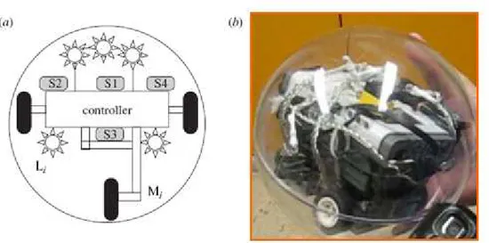
The particular mechanical structure used in this work is referred to in the following as a “ bubble robot”. Each robot is in fact shaped as a hollow sphere containing three motors as shown in
Fig.19. Even if the mechanical structure of the robots is known [28], the sensors and the communication equipment have been conceived in order to implement the mirror neuron-based control. All of the shafts are radially mounted within the hollow sphere so that an extension of them would intersect the sphere at its geometric centre. The centre of mass of the robot is also located on the axial direction of the geometric centre of the sphere. The robot has two motors fixed in the rear part of the chassis and one in front. The third motor guarantees a better control of steering. A low centre of gravity for increased stability is guaranteed by the positioning of the microcontroller, which is the heavier part of the robot.
This mechanical structure offers several advantages. The sphere in which the robot is located is realized in thick plexiglass, thus furnishing a protective structure for the robot itself. The robot can be designed to be holonomic and move in any direction. This increases its capabilities to avoid obstacles and prevents the robot from getting stuck in corners. Furthermore, a spherical robot cannot be overturned. A spherical robust robot can be ideal for homeland security, surveillance applications, autonomous exploration, pipe inspection and the entertainment industry.
The three motors are all 9 V/0.55 A DC motors. The robot inside the plastic sphere is able to maintain an always stable configuration with respect to the lower part of the sphere and to
the floor where it moves.
Fig. 19. Mechanical structure of the bubble robot: (a) schematic diagram; (b) a photo of the robot. S1, S2, S3, S4, IR sensors; Li , light-emitting diode lights (i = 1, . . . , 21); Mi , motors (i = 1, 2, 3).
The core of the robot is the microcontroller ARM7/32 bit Atmel (AT91SAM7256) with 256 kB of FLASH memory and 64 kB of RAM memory; the chassis of the robot is realized with the mechanical parts of the Mindstorms Robotics Kit. The robot has the possibility to transmit data with a BlueTooth protocol.
The choice of the sensors equipped on each robot was dictated by the aim of our experiments. As discussed in the introduction, mirror neurons are essentially visual-motor neurons. In order to simplify the complexity of the learning experiment, we let the robot move in the absence of environment light and equip the first robot, i.e. the observed robot, with a series of 21 high-intensity light-emitting diodes (LEDs) so that its relative position can be easily identified by the second robot, i.e. the observer robot, without the need of sophisticated image processing algorithms. As shown in Fig.20, this latter robot is equipped with four infrared sensors able to recognize the light emitted by the first bubble robot. Each infrared sensor (S1, S2, S3, S4) works at 9 V and i t is active on an area of approximately 90◦. The sensor displacements and
the trajectory control are conceived in such a way that the relative motion of the observed robot is easily detected. In practice, starting from its sensor inputs, the observer robot is able to understand the behaviour of the other robot in terms of its left/right or forward movements. The sensor outputs constitute four different inputs for the control system of the observer robot.
Fig. 20. Scheme of sensors on the o bserver robot.
6.3 The control system.
As introduced above, one of the two robots, called the observed robot, autonomously moves, driven by a chaotic law, while the second one, referred to as the observer robot, through a mirror neuron-like system, learns how to synchronize its trajectory to the first one. The control law is described taking into account the different behaviour of the two robots.
The observed robot is driven by a control law that specifies the velocities of each of the three motors of the robot: VM1 , VM2 and
VM3. In particular, a logistic map described by the following
equation:
zk +1 = azk (1 − zk ) (7)
with a = 4 is used. When the robot goes in the forward direction, all the three motors are switched on, while, when it turns, one of the two rear motors (M1 or M2) is switched off. The velocity of the motors is directly connected to the value of the logistic map at time t through a proportionality constant labelled as K, according to the following rule:
(8)
and
(9)
The value of the constant K was experimentally determined and fixed to K = 1000. With this simple rule, the chaoticity of the time series zk generated by the logistic map is reflected in two characteristics of the robot trajectory: the sequence of left and right turns of the observed robot is unpredictable, and the steering angle is irregular.
(b) The observer robot
The observer robot is equipped with an artificial neural network able to learn the behaviour observed in the other robot.
A Hebbian rule is implemented in order to adjust the weights of the network.
The architecture of the neural network is reported in F i g .21
showing how each input neuron receives a sensory input and how the output of the network is directly connected to the motor
system. In particular, the implemented neural network has four input
neurons (each one controlled by one of the robot sensors), one hidden layer with seven neurons and three output neurons to control robot motors.
Fig. 21. Architecture of the neural network controller.
The observer robot determines the relative motion between itself and the observed robot. The objective of the control is such that, if the observed robot makes a right turn, the observer robot must perform the same rotation, and vice versa. In particular, the neural network in Fig. 21 enables the robot to perform the actions in order to follow the motion of the observed robot. The training of the network is performed by using the motion information of the observer robot itself and the detected measurements from the observed robot in order to establish,
while the two robots are moving, a set of reinforcements for those motor signals (in the observer robot) that make the motion of both robots similar. In the real-time performance of the observer–observed robots, the network allows the establishment of motor controls in order to achieve the correct movement like that of the observed robot. Thus, it works like a mirror neurons network, in the sense that the observer robot looks at the observed robot and mimics its behaviour performing the action driven by the network.
The neurons of the network have sigmoidal activation function. The correlation between the presynaptic and postsynaptic activity is controlled by a typical Hebbian learning rule. Each synapse of the network i, j that connects the neuron j to neuron i is governed by three parameters: w 0 that represents the initial weight of the input at time t = 0 (the real value is in the range [0,1]); si,j that represents the sign of the connection (1 or −1); and hi,j that represents the learning rate and varies in the range [0, 1].
The update of the synaptic weights is performed at each time step (a sensory–motor cycle). The updating rule for the weights of the network is given by:
i,j = wi,j + hi,j · Dwi,j , (10)
where Dwi,j is defined as: Dwi,j = (1 − w t −1 ) · oj · oi
In the learning rule, oj represents the activity of the presynaptic neuron and oi the activity of the postsynaptic neuron. The learning rate h modulates the variations of Dw . The sensors placed on the observer robot activate the corresponding input neurons set to 0 if the sensor does not see the other robot and set to 1 if the sensor sees the robot.
This architecture is suitable for online learning of sensory-motor associations.
The next chapter describes the obtained results and in particular shows how some of the hidden neurons of the networks behave like mirror neurons, i.e. the same specific hidden neurons being active in two separate cases when the second robot sees the first robot and starts to imitate it, and when it does not see the observed robot but ‘unconsciously’ activates the same pattern of hidden neuron activities.
Chapter VII
Mirror Neurons Robots and immaterial art.
7.1 Chaos, Robotics and Mirror Neurons: Science, Technology and Art.
The aim of this research including cooperative robots, strange attractors synchronization, led trajectories analysis, is to complete in some features the ingredients mentioned in “From Technological To Visual Art” [13], in order to conceive robots to be integrated in virtual arts where the key element is the spectator interaction and participation [29]. The intersection between technology and art is an increasing trend in the last 20 years [2]. Science, technology and art have been connected since the 60’s, when scientists, artists, and inventors begun to cooperate and use electronic tools to create art [30].
The generation of strange attractors and emergent shapes and patterns has been widely faced in the last years [5, 3]. The wide variety of patterns based on strange attractors achieved an impressive aesthetic level such that more people worked in order to emphasize in art the impressive features of strange attractors considering chaos as a bridge between art and science [31].
Lots of engineers and researchers today design robots with special neural network brain and special mechanisms able to paint, to play music and dance [32], [33], they create Art through Technology, they realize interactive shows and interactive art-installations, they discover a new
Art through nature laws and chaotic laws [34], and also they discover Art trough science.
Other researchers study the connection and the relationships between Mirror Neurons and the imitation of gestures, relationships between Mirror Neurons, emotion and esthetic experience [35]. The study of Mirror Neurons offers the possibility of a clearer understanding of the
relationships between responses to the perception of movement within sculpture, painting, architecture and dance.
These researches reveal that Mirror Neurons have important implications not only in the process of creation of art by the artist but also “Mirror system integrates observed action of others with an individual’s personal motor artistic repertoire and suggests that human brain understands action by motor simulation” [36]. Mirror Neurons have several applications in the modelling of auditory-motor integration, in applications of interaction and imitation between human and robots [26].
Starting from the study of this literature background our research proposes an interaction between two identical Bubble Robots through the mechanism of Mirror Neurons. At the same time we analyse “the beauty of the chaotic patterns” [37] generated by the dynamics and the tra jectories described by t h e r e a l i z e d Bubble Robots.
7.2 Experimental results.
The experimental set-up consists of an arena where the two robots move and a videocamera recording the trajectories of the robots. The analysis of the robot trajectories is then performed through EXPOSURE software [38]. We carried on several experiments on different environments and initial conditions. Each test lasts for about 200 sec (each second corresponds to a sample for the network training).
At the beginning of the experiment, the observed robot turns on the LED system and moves following a trajectory driven by the logistic map control. During this first phase of the experiment, learning takes place. The observer robot receives inputs from its sensors on the basis of the movements performed by the observed robot (i.e. it is able to identify the changes of position of this robot calculated on the basis of the light emitted by its LED system). The phase of learning takes about 100 s, after which the two robots are synchronized and the observer robot follows the trajectory of the observed robot, in the sense that it mimics the actions (such as a right turn, for instance) performed by the other robot. Since the sensors perceive relative motion, to establish if the observer robot is properly working, it may be necessary to rotate/translate its trajectory before comparing it with that of the
observed robot. Fig. 22 shows two different frames of an
experiment demonstrating the synchronized behaviour of the two robot trajectories.
The experiments previously discussed clearly demonstrate the capability of the robot equipped with the neural network controller to mimic the behaviour of the observed robot. In order to demonstrate that some of the neurons of such a network behave as mirror neurons, we now show how the same pattern of neuron activation is observed under two different conditions: either when the observer robot sees and mimics the action performed by the observed robot or when the observer robot
performs the same action. In the last condition, in order to simulate an autonomous behaviour of the observer robot, the experiment was carried out by giving random signals to the sensor inputs.
Fig. 22. Synchronization between robot trajectories. Each frame represents a trajectory lasting about 8 sec.
During this autonomous navigation of the observer robot, sequences of actions similar to those registered for the observed robot can be found. We have found that such sequences of actions (or pieces of trajectories) in the absence of the observed robot are generated by the same pattern of activation generated as a result of the imitation of the observed robot in the opposite case that the observed robot is indeed operating in the arena. This behaviour was found for three of the seven neurons of the networks, thus demonstrating they have mirror neuron-like properties, since they activate either when the action is performed or is observed in another agent.
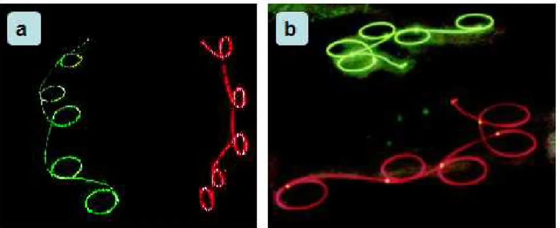
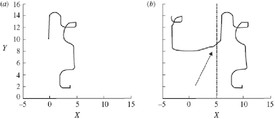
An example of such experiments is reported in Fig. 23 and F i g . 24. In Fig. 23, the trajectory followed by the observer robot in the absence of the observed robot (Fig. 23b) is compared with a part of a trajectory followed while imitating the behaviour of the observed robot. The two trajectories are similar (obviously, the similarity starts from a given time instant, since in the absence of the observed robot, the observer robot moves in an autonomous way). Corresponding to this, the activation patterns of the three
mirror neurons of the network are similar.
Fig. 23. (a) Trajectory of the observer robot in the presence of the observed robot. (b) Trajectory of the observer robot in the absence of the observed robot.
Fig. 24 shows an example for one of the three mirror neurons. Starting from t > 105 s, the activation pattern of this neuron is
similar to that which would happen in the presence of an
observed robot performing an action similar to that autonomously performed by the observer robot. The other two behave in an analogous way.
Fig. 24. Activation of neuron 1 when the observed robot is visible (a) and when it is not (b).
The experimental results discussed in this chapter show how, after learning, the observer robot is able to synchronize its trajectory to that of the observed robot and how mirror neuron-like properties can be found in the neurons of the trained network. The paradigm of mirror neurons can be thus successfully applied to robotics and, in particular, to the problem of learning how to synchronize the behaviour of chaotically driven robots.
This type of chaos-based trajectory control substantiates the possibility of generating random trajectories needed for tasks such as exploration with easy distributed coordination strategies needed
to control groups of robots instead of single units.
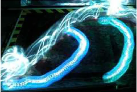
In several experiments the trajectories are often symmetrical with respect to an hypothetical diagonal line that divides the arena in which robots move: this confirms the imitation properties of the two robots. A gallery of trajectoryes of the synchronized robots is shown in the following pictures: Fig. 25, Fig. 26, Fig. 27, Fig. 28, Fig. 29, Fig. 30, Fig. 31, Fig. 32.
The visive effects of the synchronization of the twins mirror neuron robots is very suggestive: the strange shapes and patterns carried out by the described experiments show us a new way to research the beauty of “art through technology” [39].
Fig. 25. Artistic pattern created by the synchronization of the two bubble robots (after 195 sec).
Fig. 26. Artistic pattern created by the synchronization of the two bubble robots (after 110 sec).
Fig. 27. Artistic pattern created by the synchronization of the two bubble robots (after 185 sec).
Fig. 28. Artistic pattern created by the synchronization of the two bubble robots (after 110 sec).
Fig. 29. Artistic pattern created by the synchronization of the two bubble robots (after 110 sec).