Tesi di Laurea Specialistica di: Luca VACCARO
Matr. 755789
POLITECNICO DI MILANO
Facoltà di Ingegneria
Corso di Laurea Specialistica in Ingegneria Informatica
Dipartimento di Elettronica e Informazione
A REAL-TIME, RELIABLE AND
REPROGRAMMABLE FRAMEWORK
FOR HYBRID SENSOR NETWORKS
Relatore: Ing. Manuel Roveri Correlatore: Ing. Romolo Camplani
Contents
Abstract 5 1. Introduction 7 1.1. WSN overview . . . 7 1.2. Reel objectives . . . 8 1.2.1. Reprogrammability . . . 8 1.2.2. Maintenance . . . 9 1.2.3. Security . . . 91.2.4. Robustness and safety . . . 10
1.2.5. Performance . . . 10
1.2.6. Usability and scalability . . . 10
1.3. Reprogramming scenarios . . . 11
2. State of the art 13 2.1. Operating systems for WSN nodes . . . 13
2.2. Reprogramming techniques . . . 15
2.2.1. Complete reprogramming . . . 15
2.2.2. Incremental patches . . . 16
2.2.3. Virtual Machine-based reprogramming . . . 16
2.3. Loadable Modules . . . 17
2.4. Proposed solution . . . 19
3. Design 21 3.1. Sensor and Gateway nodes architecture . . . 22
3.2. Hardware . . . 23 3.3. Kernel layer . . . 24 3.3.1. FreeRTOS . . . 24 3.3.2. Device driver . . . 25 3.4. Services Layer . . . 25 3.4.1. Communication service . . . 25
3.4.2. Remote command interface service . . . 26
3.4.3. Loader service . . . 27
3.4.4. Software faults handling service . . . 27
3.4.5. Boot and restart services . . . 28
Contents Contents
3.5. Application Layer . . . 29
3.5.1. WSN node monitoring applications . . . 29
3.5.2. Control Room applications . . . 30
3.6. REEL tool-chain . . . 30 4. Implementation 31 4.1. Kernel space . . . 32 4.1.1. Kernel structure . . . 32 4.1.2. FreeRTOS’s tasks . . . 33 4.2. Reprogramming model . . . 33
4.2.1. Concurrent programming model . . . 34
4.2.2. Job state . . . 34
4.2.3. Job structure . . . 35
4.3. Jobs manager . . . 36
4.3.1. Jobs table . . . 36
4.3.2. Jobs operations . . . 38
4.4. Remote command interface service . . . 40
4.4.1. Communication protocol . . . 41 4.4.2. Job payload . . . 41 4.5. Exception service . . . 41 4.5.1. Classification . . . 42 4.5.2. Specification . . . 43 4.5.3. Policies . . . 44 4.6. Loader service . . . 44
4.7. Boot and restart service . . . 45
4.8. Development tool-chain . . . 46
4.8.1. Configuration script . . . 47
4.8.2. Compile and link the system . . . 47
4.8.3. Compile and link the job . . . 50
5. Evaluation 53 5.1. Concurrent applications . . . 53 5.2. Energy Consumption . . . 53 5.3. Memory Consumption . . . 54 5.3.1. Kernel space . . . 55 5.3.2. Services . . . 56 5.3.3. Applications . . . 56 5.4. Execution Overhead . . . 56 5.4.1. Reprogramming time . . . 57 5.4.2. Booting time . . . 57 5.5. Results . . . 58 6. Conclusions 61
Contents A. Installation manual 63 B. Eclipse settings 67 C. Geting started 69 Bibliography 71 Bibliography 71
List of Figures
2.1. Reprogramming methods . . . 13
2.2. The memory architecture of the Contiki memory [7]. . . 19
2.3. The dynamic linking mechanism of Contiki [7] . . . 20
3.1. REEL over the network . . . 22
3.2. The architecture of the REEL node . . . 23
4.1. Sram and Flash memories . . . 31
4.2. Job states . . . 35
4.3. Job structure and memory addressing . . . 36
4.4. Format of REEL packet . . . 41
4.5. Format of REEL application packet . . . 42
4.6. Sram and Flash memories . . . 48
4.7. Compile and link chain . . . 50
5.1. Concurrent blink applications . . . 54
5.2. Reprogramming time . . . 57
5.3. Booting time . . . 58
List of Tables
1.1. The reprogramming scenarios on WSN . . . 12
5.1. Blink application size for different reprogramming solutions . . . 55
5.2. Flash and Sram memory consumption for kernel space. . . 55
5.3. Flash and Sram memory consumption for services. . . 56
5.4. Flash and Sram memory consumption for applications. . . 56
5.5. Quantitative comparative of reprogramming methods . . . 58
Abstract
In questa tesi presentiamo la progettazione ed implementazione del framework REEL, un framework per reti di sensori orientato alla riprogrammazione remota. Il frame-work REEL si basa sul sistema operativo FreeRTOS, estendendone le funzionalità di base, fornendo in particolare dei servizi aggiuntivi per gestire la gestione remota delle applicazioni installate sul nodo di una rete di sensori.
La riprogrammazione remota del nodo consiste nell’iniettare un nuovo codice ap-plicativo sul nodo a run-time, senza necessità di intervento diretto dell’operatore umano. Questa caratteristica permette, ad esempio, di cambiare il comportamento del nodo, la configurazione e gli algoritmi, direttamente dalla stazione di controllo, senza modificare il sistema di base del’OS. La politica di riprogrammazione a livello di applicazione intrapresa permette di caricare sul nodo una nuova applicazione, o sovrascrivere una esistente, senza effetti collaterali sulle applicazioni eseguite in modo concorrente. A questa precedura si affiancano servizi avanzati per fornire:
• contesto di esecuzione protetto delle applicazioni: permette di rilevare i soft-ware faults, notificare le eccezioni e bloccare le relative applicazioni difettose evitando il blocco dell’intero sistema
• monitoraggio remoto del sistema: rileva il livello di utilizzo del sistema, le applicazioni installate, la memoria disponibile, ed eventuali valori caratteristici quali il livello della batteria
• gestione remota delle applicazioni: consente il caricamento, l’esecuzione e l’arresto delle applicazioni senza riavvio della macchina
• procedura di riavvio: ripristina la configurazione iniziale del sistema e riavvia le applicazioni schedulate, portando il sistema in uno stato consistente. • metodo di riprogrammazione sicuro: verifica l’integrita’ e l’autenticita’ delle
applicazioni prima di effettuare l’installazione sul nodo
Non di minore importanza sono gli strumenti software forniti da REEL per la stazione di controllo:
• ambiente di sviluppo di alto livello per sviluppare nuove applicazioni basate sul REEL framework
• compilare ed rilocare il codice, linking statico, delle applicazioni in modo au-tomatico
Chapter 0 List of Tables • effettuare il debug delle applicazioni
• strumenti per il monitoraggio delle attività su ciascun nodo e lo stato della rete
• interfaccia utente per monitorare ed interrogare il nodo remoto, noonchè cari-care nuove applicazioni
Il tema della riprogrammazione remota e’ abbastanza recente in letteratura e sono stati proposti numerosi approci. REEL si propone buon compromesso fra il con-sumo energetico e prestazioni, e puo’ essere adattato per svariate tipologie di sce-nari. La politica di riprogrammazione si basa sul linking statico delle applicazioni nella stazione di controllo, la diffusione dell’immagine verso il nodo remoto, e la relativa esecuzione. Questa procedura permette da un lato di minimizzare le infor-mazioni scambiate durante la comunicazione rispetto al linking dinamico; dall’altro lato, fornisce un’esecuzione nativa del codice macchina, senza introdurre overhead temporali tipici di soluzioni basate su macchina virtuale.
1. Introduction
The goal of this thesis is to design and implement REEL, an novel framework for Wireless Sensor Network. The REEL framework is based on the lightweight, real time, operating system FreeRTOS aiming to extends its basic functionalities, which are limited to the scheduler and the memory management. In particular, REEL is a complete framework oriented to the remote reprogramming, which consists in injecting new codes in to nodes at run-time. This feature, for example, allows to change the configuration and the algorithms on the remote node directly from the Control Room. Since the remote reprogramming is not a completely new subject on the WSN literature, we want to focus on the following key features:
1. the ability to load more than one single application without affecting the others running applications,
2. the ability to kill a bugged application and thus to “protect” the execution from exceptions.
Other aspects such as the code dissemination optimization, while important, are not directly addressed by REEL in the sense that we relies on existing solutions. Moreover REEL framework provides a development environment to write and debug applications, a complete tool-chain and a simple mechanism to propagate the new code over the network.
The thesis is organized as following. In the first chapter we present the problem of the remote reprogramming in the WSN. In the second chapter, we discuss the main operating systems for WSN and the reprogramming methods present in the literature. In the Design and Implementation chapters, we present the architecture of REEL and our practical realization. In the fifth chapter, we present the experimental results and finally, in the last chapter, we show the final remarks.
1.1. WSN overview
We consider a monitoring system for environmental and structural applications com-posed by a set of remote monitoring systems (RMSs) deployed in the environment to observe the physical phenomena of interest and by a Control Room that col-lects data from remote systems for processing, analysis and storage. The hybrid wired-wireless architecture of the RMS is composed by:
Chapter 1 Introduction • a cluster of sensing and processing units (sensor nodes): acquire and locally process signals (e.g., MEMS, geophones, temperature sensor, strain gauges) • a base station (gateway node) connected to all sensor nodes of his RMS:
gate-way nodes collects the acquisition from the sensor nodes and remotely transmit them to a control room for storage and analysis.
The proposed architecture uses different hardware platforms and system software for two class of nodes: DSPIC33F microcontroller with FreeRTOS for sensor nodes and 200MHz ARM9 CPU with Linux for gateway nodes. Our idea is different: a generic and stable hardware/software embedded system, configurable for a specific domain. The hardware platform is defined in the “NetBrick: a high-performance, low-power hardware platform for wireless and hybrid sensor network” [4] article, developed at Politecnico di Milano.
1.2. Reel objectives
Nowadays an update in a Wireless Sensor Network requires to disassemble the entire network. This procedure is really expensive and not always feasible. In this scenarios we are not only interest about the value detected by the sensors, but we want to know also the internal state of a remote node: running applications, configuration parameters (clock frequency), battery life, software faults and etcetera. Moreover we want to install and debug our applications on the remote node without disassemble the entire network. This is REEL OS. The main targets of REEL are:
• an efficient and secure reprogramming method • an safe execution context per applications
In this thesis we explain in details all the mechanism of REEL solution. In specify, the main peculiarities are:
• Reprogrammability • Maintenance
• Security
• Robustness and Safety • Performance
• Usability and scalability
1.2.1. Reprogrammability
The main focus of REEL is the ability of reprogramming. The term reprogramming means the ability to load a new application or overwrite an existed one over a remote
1.2 Reel objectives
sensor node. The load procedure looks like the installation methods of traditional computer system. The node supports a collection of applications which define the tasks and the algorithms to perform. The application can be insert, or install, delete or overwritten but the basic system must be unchangeable. The kernel and the services must be solid components to provide a high level of reliability. In the next section we present the reprogramming scenarios and analyze different kinds of situations.
1.2.2. Maintenance
In the software life cycle, the maintenance phase is the last stage of the cycle. During the maintenance phase of the software life cycle, software programmers regularly issue software patches to address changes in the needs of an organization, to the main reasons:
• correct issues relating to bugs in the software or resolve potential security issues
• prevent any hindrance to the expected performance of the software • add increased functionality to the software
In the WSN domains, the application must satisfy the constrains due to the embed-ded platform.
REEL provides two main levels of maintenance:
• system: the kernel, device drivers, services are unchangeable
• user applications: can be update through reprogramming procedure
The system maintenance allows to manager the internal state of the remote machine. The control room can remotely access to the node and set the current configuration. In specify, the system maintenance lets to:
• monitoring the internal information of a node: battery status, used memory • monitoring the user applications: list of installed, scheduled or running
appli-cations
• notify the software faults and select the politics to use
1.2.3. Security
The application can be signed for a specific devices, so nobody, unless the owner, can modify the binary. This security feature does not allow malicious person or virus to infect the application. A mechanism with cryptographic signatures avoids this hole in the security and increase the availability of the system.
Chapter 1 Introduction
1.2.4. Robustness and safety
In the perfect world, the applications have no bugs and the system never crash. But we are in the real word and sometimes the things don’t go as you want. Sometimes the application profiling and simulating are not enough and they do not satisfy all possible scenarios. For example the application faults are not unusual: division by 0, access to a protected or invalid memory address. In the classic systems for WSN, the kernel and the applications are merged together, and if the application gets a fault, the system gets a fault, and the platform stops to work and resets itself. After reboot, the system execute the application again and it resets itself one more time. So we built a useless machine that consumes a lots of energy. A robust framework should recognize the software faults and block the bugged application. The system marks the application as not-executable, and it is never executed anymore.
1.2.5. Performance
The sensor node applications usually performs cyclic operations: sampling the val-ues, local process and eventually transmit the results. These operations are per-formed in a well-defined interval of time. At the diminution of time interval length, follows the increase of the frequency increase and in high frequency applications, the frequency becomes one of the criticality of the system. In general a sensor node can sampling data at rate of 10/100Herz or more. To guarantee this rate we define two conditions for OS. First, an application, with cyclic behavior, must start exactly at the begin of the time period; the Real-Time scheduler of REEL satisfies this require-ment. The second condition consists to verify that the application does not violate the frequency rate. A single cycle of the application must not exceed its period of time. The sampling frequency is set ad-hoc by the operator. The system should not introduce time overhead during the execution of the application. For this reason, the REEL reprogramming method, based on binary code, is much performed than virtual machine approach.
1.2.6. Usability and scalability
Many solutions in literature provides good reprogramming methods but many of them are hard to use. The complexity is due to: poor documentation, insufficient software tools and few library functions. Moreover the framework often doesn’t help the operator with a common interface to exchange information over the network. We can exchange various information about the WSN node and collect them in the Control Room. In the Control Room different kinds of operator can interface with the system:
• Developers: write and debug their applications with a development environ-ment, build the binary image with the tool-chains, and test the remote system
1.3 Reprogramming scenarios
• Administrators: configure the nodes and monitor the network
• Observers: after an high-level synthesis, read the values received from the sensor nodes.
We focus our project for the firsts two kinds of operator that directly interface with the WSN nodes and REEL framework.
1.3. Reprogramming scenarios
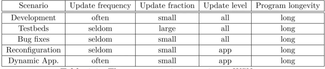
Software updates for sensor networks are necessary for a variety of reasons ranging from implementation and testing of new features of an existing program to complete reprogramming of sensor nodes when installing new applications. In this section we review a set of typical reprogramming scenarios and compare their qualitative properties.
• Software development is an iterative process where code is written, installed, tested, and debugged in a cyclic fashion. Being able to dynamically reprogram parts of the sensor network system helps shorten the time of the development cycle. During the development cycle developers typically change only one part of the system, possibly only a single algorithm or a function. A sensor network used for software development may therefore see large amounts of small changes to its code.
• Sensor network testbeds are an important tool for development and experi-mentation with sensor network applications. New applications can be tested in a realistic setting and important measurements can be obtained. When a new application is to be tested in a testbed the application typically is installed in the entire network. The application is then run for a specified time, while measurements are collected both from the sensors on the sensor nodes, and from network traffic. For testbeds that are powered from a continuous energy source, the energy consumption of software updates is only of secondary im-portance. Instead, qualitative properties such as ease of use and flexibility of the software update mechanism are more important. Since the time required to make an update is important, the throughput of a network-wide software update is of importance. As the size of the transmitted binaries impact the throughput, the binary size still can be used as an evaluation metric for sys-tems where throughput is more important than energy consumption.
• Correction of Software Bugs in sensor networks was early identified. Even after careful testing, new bugs can occur in deployed sensor networks caused by, for example, an unexpected combination of inputs or variable link connectivity that stimulate untested control paths in the communication software. Software bugs can occur at any level of the system. To correct bugs it must therefore be possible to reprogram all parts of the system.
Chapter 1 Introduction • Application Reconfiguration in an already installed sensor network, the appli-cation may need to be reconfigured. This includes change of parameters, or small changes in the application such as changing from absolute temperature readings to notification when thresholds are exceeded. Even though reconfig-uration not necessarily include software updates, application reconfigreconfig-uration can be done by reprogramming the application software. Hence software up-dates can be used in an application reconfiguration scenario.
• Dynamic Applications in many situations where it is useful to replace the application software of an already deployed sensor network. One example is the forest fire detection scenario presented where a sensor network is used to detect a fire. When the fire detection application has detected a fire, the fire fighters might want to run a search and rescue application as well as a fire tracking application. While it may possible to host these particular applications on each node despite the limited memory of the sensor nodes, this approach is not scalable. In this scenario, replacing the application on the sensor nodes leads to a more scalable system.
Scenario Update frequency Update fraction Update level Program longevity Development often small all long
Testbeds seldom large all long Bug fixes seldom small all long Reconfiguration seldom small app long Dynamic App. often small app long
2. State of the art
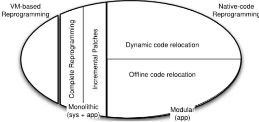
In this section we present a brief introduction of the available operating systems for embedded devices and in particular for wireless sensor network nodes. In particular, we will analyze the reprogramming methods supported by several OSs. Among the techniques present in the literature, we investigate:
• complete reprogramming: the entire program image, which contains the ap-plication and the OS is replaced by a new version; the size could be very large;
• incremental patches: only a delta is transmitted and replaced; the size is reduced;
• virtual machines: the application is based on a virtual machine byte-code, optimized in space for reduced transmission overhead
• loadable modules: applications and services are loaded at run time without modifying the OS
Figure 2.1.: Reprogramming methods
2.1. Operating systems for WSN nodes
The WSN node operating system are a key component in of the WSN-based ap-plication software stack. The internal architecture of an OS has an impact on the size on the overhead in terms of memory footprint and, from the development point of view, how it provides services to the application programs. The common OS architectures are the following:
Chapter 2 State of the art • monolithic architecture: in the monolithic architecture (i.e., TinyOS, Nano-RK), the kernel provides all the services (e.g., device drivers, communication protocols, memory management, etc.). Such an architecture allows bind all the exported services together into a single system image, thus allowing to op-timize the OS memory footprint. An advantage of the monolithic architecture is that the module interaction costs are low because the kernel space shares functions and variables among modules.
• modular architecture: modular architecture (used in FreeRTOS) exposes only basic set of functionality (i.e., memory management, scheduling). Other services (e.g., device drivers, network protocols, etc.) are relegated to external processes (such as the UNIX daemons). in modular kernels the modules are in practice separated processes that communicate each other by using the inter process communication (IPC) kernel service. In particular, the IPC provides mechanisms such as communication queues, semaphores and shared memo-ries for both external services and applications. The main advantage of the modular kernel to complete decouple the modules via IPC, which eases the testability and maintenance of the system. The drawback of such approach consists in the augmented complexity in terms of memory required an CPU time to handle the IPC service w.r.t. the typical sys-call of the monolithic kernel.
Another important key to compare OSs are the programming model supported, which has a significant impact on the application development. There are two main programming models provided by typical WSN OSs:
• event driven programming: it is optimized for low-end devices, but difficult and error prone not from the developer point of view. It lets the micro-controller sleep as much as possible (it wake-up only to react to external events), thereby achieving energy-efficiency.
• multi-threaded programming: it is the classical application development model, but it require a not negligible overhead in terms of memory required and then not well suited for resource constrained devices such as sensor node. Statically allocating per thread stack is often too expensive in terms of mem-ory space. Many contemporary on developing a light-weight multi-threading programming model for WSN OSs.
TinyOS [18] is one of the most widely used monolithic operating systems for WSN. TinyOS is written in NesC [9], a programming language based on C, and is a component-based OS, allowing modular programming. Its level of abstraction is very low and it is often difficult to implement even simple programs. In addition, rig-orously event-based style and exclusion of blocking operations are often the sources of complexity. Fiber [30]is a lightweight concurrency model for TinyOS and allows a single blocking execution context along with TinyOS event-driven concurrency model.
2.2 Reprogramming techniques
Mantis OS [1] is at the other end of spectrum: it provides preemptive, time-sliced multi-threading on MICA2 motes. TinyThreads [30] , Proto-Threads [8] and Y.Threads [24] are in the intermediate level between Fiber and Mantis OS. TinyThread is a multi-thread library for TinyOS. Proto-threads are a multi-threading library for Contiki [7], which is an event-based operating system. Proto-threads are similar to TinyThread in that they also adopt the cooperating multi-threading.
2.2. Reprogramming techniques
The reprogrammability feature is something realized in middleware. Some examples are Impala [22] and SensorWare [2]. Impala is a middleware designed for ZebraNet project [14] and its goal is to enable application modularity, adaptability to dynamic environments, and repairability. Its modular design allows easy and efficient on-the-fly reprogramming via wireless channel. SensorWare supports Tcl-based control scripts for the language used for reprogramming. Compared to virtual machine, SensorWare is designed for a richer hardware platform such as iPAQ.
Some operating systems have started to feature a dynamic reprogramming capabil-ity. Deluge [12], a dissemination protocol, with TOSBoot boot-loader enables an in situ code update for TinyOS, Mantis OS [1] , Contiki[7], and SOS [10] also support dynamic update in finer resolution such as module and thread for more efficiency.
2.2.1. Complete reprogramming
The full image replacement is the easiest way to reprogram a sensor node by re-distribution of the program. However, reprogramming cost is high because the image size can be large several kilobytes. Moreover, after the completion of downloading process, the sensor nodes must reboot themselves to activate the new image, causing the operation of sensor nodes to be stopped and the current execution state to be lost. Although an external mechanism can be provided to save the execution state to non-volatile memory and restore it after the reboot, this approach is still an expensive operation.
TinyOS [18] is the primary example of an operating system that does not support loadable program modules in the standard release. Several protocols provide repro-gramming of the full system, such as Deluge[12], Stream [26], Freshet [16], MOAP [28], and MNP [17].
Deluge[12], a reliable data dissemination protocol for disseminating a large data ob-ject (i.e. larger than can fit into RAM) from one or more source nodes to many other nodes over a multi-hop wireless network. Deluge’s density-aware, epidemic proper-ties help achieve reliability in unpredictable wireless environments and robustness when node densities can vary by factors of a thousand or more. Representing the
Chapter 2 State of the art data object as a set of fixed-size pages provides a manageable unit of transfer which allows for spatial multiplexing and supports efficient incremental upgrades.
2.2.2. Incremental patches
The differential patching schemes, or incremental code update, allow to reduce the amount of data transmitted during reprogramming. Based on the assumption that image changes such as bug fixes are usually small, they only distribute the binary differences between the original system image and the new one. After receiving the differences, the new image could be generated from the received differences and the current image stored on the sensor node. However, since previous differential patching schemes are based on XNP[5], sensor nodes still need to reboot themselves to execute the new image.
To support incremental reprogramming Jeong [13] use Rsync to compute the dif-ference between the old and new program images. However, because it is built on top of XNP [5], it can only reprogram a single-hop network and does not use any application-level modifications to handle changes in function locations. In 2003 Rei-jers and Langendoen, the authors modify Unix’s diff program to create a edit script to generate the delta. They identify that a small change in code can cause many address changes resulting in a large delta. Koshy and Pandey use slop, empty, re-gions lead to fragmentation and inefficient use of the Flash memory. Also when the function references to change and size of the delta script to increase.
Zephyr[25], a fully functional incremental multi-hop reprogramming protocol, is an extension of Rsync algorithm to reduce the size of the delta. The delta script is transmitted wirelessly to all nodes in the network in a multi-hop manner. The nodes save the delta script in their external flash memory and then build the new image using the delta and the old image and store it in the external flash. Finally the boot-loader loads the newly built image from the external flash to the program memory and the node runs the new software. Zephyr uses techniques like function call indirections to mitigate the effect of function shifts for reprogramming of WSN node.
2.2.3. Virtual Machine-based reprogramming
The idea is to provide an application-specific virtual machine, which is designed for a particular application domain and provides the needed flexibility, so that it can support a safe and efficient programming environment. The motivation for being application specific is based on the observation that WSN are usually deployed for a certain application purpose, unlike the Java virtual machine that is generic enough. Since virtual machines provide a higher level interface, the size of the byte-code is extremely small as compared to the native code image. This is attractive in WSNs since it reduces the energy for code dissemination during reprogramming.
2.3 Loadable Modules
Although reprogramming costs are cheap, the cost of running virtual machines on devices with strict resource constraints such as sensor nodes would be high. This is because dynamically interpreting byte-codes can have a significant computational overhead. Finally, the reprogramming ability is applied only to applications running on the virtual machine for a limited number of instructions. Moreover it is not possible extend on-the-fly the supported instructions.. Neither the virtual machine itself nor the kernel can be reprogrammed. Maté [19]and ASVM [21, 20] are stack-oriented virtual machines implemented on top of TinyOS. Melete [31] extends Maté and supports multiple concurrent applications. VMStar [15] allows the dynamic update of the system software such as VM itself, as well as the application code. In the licterature there are several application specific VM based on Java, example Darjeeling [3].
2.3. Loadable Modules
A loadable module contains the native machine code of the program that is to be loaded into the system. The machine code in the module usually contains refer-ences to functions or variables in the system. These referrefer-ences must be resolved to the physical address of the functions or variables before the machine code can be executed. The process of resolving those references is called linking. Linking can be done either when the module is compiled or when the module is loaded; we can identify the two different cases:
• pre-linked, or static, module contains the absolute physical addresses of the referenced functions or variables whereas a dynamically linked module contains the symbolic names of all system core functions or variables that are referenced in the module. This information increases the size of the dynamically linked module compared to the pre-linked module.
• dynamic linking has not previously been considered for wireless sensor net-works because of the perceived run-time overhead, both in terms of execution time, energy consumption, and memory requirements.
With dynamic linking, the object files do not only contain code and data, but also names of functions are variables of the system core that are referenced by the module. The code in the object file cannot be executed before the physical addresses of the referenced variables and functions have been filled in. This process is done at run time by a dynamic linker. SOS [10] and Contiki[7] are examples of operating systems that support dynamically loadable modules in WSNs. Furthermore, when an existing module needs to be upgraded, it must be completely removed and its current state and allocated system resources must be discarded. Thus, the new module needs to be run from the beginning and to acquire the necessary resources again. This not only increases the reprogramming latency but also degrades the system availability.
Chapter 2 State of the art The main advantage to choose the loadable module solution are:
• high execution performance: the code is compiled for the specific target, at different of virtual machine
• low overhead in transmission: transmit only the module application instead the full image
• higher usability: it is not necessary know exactly the current state of full image in the node, like the differential patching scheme
The high complexity of dynamic linking increases the amount of traffic that needs to be disseminated through the network to transfer the symbol and relocation tables to the node for runtime linking. Moreover the symbol table consumes a considerable amount of FLASH memory. On the hand, in the pre-link solution, the linking procedure is performed by the base station without exchange symbol information. The base station need to know information about the current state of the sensor node: the allocated and free memory segments.
Contiki is a lightweight open source OS written in C for WSN sensor nodes. Contiki is a highly portable OS and it is built around an event-driven kernel. A typi-cal Contiki configuration consumes 2Kilobytes of RAM and 40 Kilobytes of ROM. A full Contiki installation includes features like: multitasking kernel, preemptive multi-threading, proto-threads, TCP/IP networking, IPv6, a GUI, a web browser, a simple telnet client. The Contiki OS follows the modular architecture. At the kernel level it follows the event driven model, but it provides optional threading fa-cilities to individual processes. The Contiki kernel comprises of a lightweight event scheduler that dispatches events to running processes, Protothreads[8]. The Contiki architecture is composed by:
• Core: kernel, device drivers, standard applications, parts of C library and symbol table. It includes the meta-information about the loadable programs • Loadable programs: load at the top of core; they have full access to the core
functions and variables. Each loadable programs is a module, a binary code unloadable into the system.
The reprogramming methods of Contiki is based on the dynamic linking procedure; we can distinguish two main steps of the reprogramming methods:
• linking: link the symbol name of the functions and variables into the physic address, before the execution of the code (compile-time o load-time).
– pre linking : link the reference into physic address – dynamic linking: link the reference into symbol name
• relocation: bind the reference of functions an variables of a same module. (compile-time o run-time)
The complexity of the system requires the minimum dimension of the system symbol table of 4 Kbytes of ROM.
2.4 Proposed solution
Figure 2.2.: The memory architecture of the Contiki memory [7].
2.4. Proposed solution
In this thesis we propose REEL, a framework oriented for remote reprogramming, based on the FreeRTOS real-time OS. The reprogramming method is based on load-able modules. This approach provides a low code dissemination and high perfor-mance on execution. Moreover it allows the developer to write applications com-pletely separated from the underlining kernel and libraries and upload only the applications to the sensor nodes.
In specific, REEL implements the pre-link, or static linking, method to decrease the overhead due to the binary transmission and reduce the energy consumption. Instead dynamic linking, REEL does not dissemination the symbol tables and the linking phase is performed by the base station during the generation of the binary code. So it is necessary that the base station know the free memory regions over the sensor node. This constrain is less strong than differential patching scheme: we need to know exactly the full image on the current system.
On the sensor node side, the reprogramming procedure is very easier: the system stores the binary code exactly into the specified region of memory.
Chapter 2 State of the art
3. Design
REEL is a framework based on the FreeRTOS operating system. In particular, the presented framework is a collection of software services:
• Remote reprogramming mechanism • Safe execution context for applications • Remote debug of system and applications • Monitoring system and applications
It is worth noting that the REEL frameworks relies on standard communication protocols (e.g., ZigBee, 6loWPan etc) to manage the local network aspects. In fact, the focus of the entire framework is to provide a robust mechanism to remote reprogramming a WSN nodes; we are not interested to present a reliable way to disseminate the program because they already exist valid solutions in the literature (e.g., SINAPSE [27]).
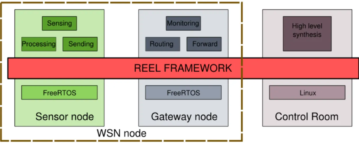
In the classical WSN system hierarchy exists three main components, in general differing for hardware capabilities and software architecture. The communication back-bone provided by the network-layer allows to exchange data, parameters, com-mands and either application. Those three components are:
• Control Room: monitors the state of the network and the state of each node • Gateway node (GW): coordinates the entire network and is able to
communi-cate with the control room
• Sensor node (SN): has the role to sense and locally process the measurements coming from attached transducers; the gathered data are routed to the GW node.
Typically GW and SN have different hardware; however in our system the GW and SN share a similar hardware architecture: the NetBrick mote. Since the NetBrick architecture is modular, the difference between GW and SN consists only in the hardware modules configuration (a further discussion about NETBRICK hardware is presented in "NetBrick: a high-performance, low-power hardware platform for wireless and hybrid sensor network" artivle[4]). Thus, the SN and GW sports a similar software architecture and, in particular, they have the same operating system but different the services (provided by REEL) installed.
In the following paragraphs, we briefly introduce the hardware architecture used as foundation of the REEL framework, then we introduces all the layers composing
Chapter 3 Design
Figure 3.1.: REEL over the network
REEL with a special focus on the remote reprogramming procedure. We present, also the REEL framework at the Control Room level, which allows to write, compile, monitor and transmit an application to a WSN node.
3.1. Sensor and Gateway nodes architecture
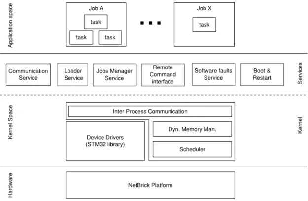
The REEL framework provides a Real-Time OS with a robust execution context and protection mechanisms for a secure remote reprogramming procedure for the WSN node. Moreover it provides a complete development environment for writing, debug the applications and a set of tools for the control room to interact and install applications on the WSN node. For this reason without loss of generality, in the rest of the paper we will consider REEL framework for a generic WSN node and the behavior depends on the installed applications. The software architecture layers are the following:
• hardware: The NetBrick[4] board is equipment with a STM32F103ZE pro-cessor based on ARM CORTEX M3, an low-power architecture for embedded systems.
• kernel space: REEL framework abstract from the hardware platform to pro-vide an execution environment for applications. It is composed by two main parts:
– kernel: is responsible to manage the hardware and to provide basic func-tionalities used by higher levels. It mainly consists of the operating sys-tem and low-level libraries.
– services: provides secure reprogramming, robust execution environment and remote command interface services.
3.2 Hardware
• application space: is the top of the described software stack and uses all the features provided by the underlying layers.
In the next sections we present in details each REEL layers.
Figure 3.2.: The architecture of the REEL node
3.2. Hardware
An efficient, adaptive and reliable software architecture is essential to locally process signal acquired up to high frequency, to guarantee synchronism among the acqui-sition units and to provide the mechanism to update the behavior of RMS nodes during the operational life. The choice of the appropriate system layer architecture for each hardware platform with its specific constraints is crucial. The WSN nodes are equipped with the NetBrick board[4], developed at Politecnico di Milanobased. This board is equipped with the STM32F103RB processor by ST Microelectronics. The limited memory does not allow to run a general purpose operating system such as Linux. Therefore, we employed an embedded real-time operating system that guarantees real time elaboration on high frequency and provides tools and services for software managing. The principal component of the architecture is the ARM 32-bit CortexTM-M3 CPU Core. The main properties of this processor are the following:
Chapter 3 Design • 20 Kbytes of SRAM memory for volatile data
• 256 or 512 Kbytes of Flash memory for permanent data and executable code • Low power: Sleep, Stop and Standby modes
The FLASH memory is grouped in blocks of 2Kbytes. This observation is funda-mental to develop an efficient reprogramming method. Moreover the NetBrick board has a lots of additional peripherals as:
• debug mode: Serial wire debug (SWD) & JTAG interfaces
• communication interfaces: USARTs (ISO 7816) and CAN interface
The NetBrick board is not the only board supported by REEL. We executed and tested successfully REEL under STM3210E-EVAL, the ST Microelectronics devel-opment board. So REEL can be installed in several STM32 boards equipped with enough memory for store the kernel and the applications.
3.3. Kernel layer
The kernel is the first software layer to provide an abstraction level from the hard-ware. It is composed by the ST Microelectronics low-level libraries and the FreeR-TOS, an real-time operating system for embedded devices. Our proposed solution uses software components from third parties to guarantee security and reliability. FreeRTOS is mostly used in embedded system and a lots of company used it for business purpose. Although these software components are not provided with the REEL, they can be freely downloadable and usable from their website.
3.3.1. FreeRTOS
The proposed REEL framework is based on FreeRTOS, a real time operating system for embedded devices, with its low overhead in terms of memory foot print (an essential feature in memory constrained devices) and a real time scheduler to verify in advance the scalability of the processes running. Moreover FreeRTOS supports a large set of boards and interacts with the ST low-level libraries which contains functions to access to the hardware devices. We choose FreeRTOS because:
• native support different architectures and development tools. • reliable and undergoing continuous active development. • minimal ROM, RAM and processing overhead.
• very scalable, simple and easy to use.
3.4 Services Layer
In the other hand, FreeRTOS does not include all the concepts of a complete kernel system: it doesn’t provide the abstraction of applications, advanced services or device libraries. REEL aims to complexity provides a model of the application, the job, that can be stored, execute and transmit over the network.
3.3.2. Device driver
The NetBrick board is equipped with a processor of the STM32 family. ST Micro-electronics provides the support for their components composed by documentation, schematics, libraries and demo projects under copyright. We are interesting in the library of low-level for interacting with registers and peripherals. Each peripheral is linked to the processors with a specific port and each port is mapped in one or more processor register. We make a different from other solutions, because we are not interested to build a new Open Source low-level library, but we want use the ST standard library.
3.4. Services Layer
The services layer extends the functionalities of a common OS, like FreeRTOS, to became a complete framework system. REEL framework provides the abstraction of high-level application as independent program. Our main focus is the ability to reprogram the remote node and manage the current execution of the remote applications. For this purpose we define cross-services between WSN nodes and Control Room:
• remote command interface service: interaction between the Control Room and the WSN node.
• secure reprogramming service: install an application on the remote note with static linking method and verified the authenticity of the application. • software faults manager: manage the exceptions to guarantee a robust
exe-cution environment and notify the fault to the Control Room.
• communication service: is the interface to send and receive data over the network
3.4.1. Communication service
The communication layer is responsible to transport data, parameters and com-mands for the reprogramming procedure between the node and the Control Room. In specify we can split the communication in two different class:
Chapter 3 Design • commands: the Control Room interacts with the node to read the current
status of the system and reprogramming a specific job.
Although in our realization the local communication is based on ad-hoc protocol, we don’t want to focus on a specific the communication protocol. In real system communication protocol is chosen by the topology of the network and the nature of the application domain. In the following we list the main quality of a communication layer:
• the topology of a network determinate a single hop or multi-hop routing algo-rithm.
• adaptive routing algorithm to topology adaption
• unit can run out of power with subsequent no wished disconnection from the network.
• easy scalability of the WSN network
• quality of service of communication among units is affected both meteorological and environmental
• conditions as well as electromagnetic pollution
3.4.2. Remote command interface service
The RCI provides a standard communication interface between the Control Room and the node through a set of commands that will be will be executed on the remote node. A key aspect of our architecture is the ability to interact with the node to acquire data information, read the current status of the system and reprogram a job. In specific we consider two different access levels for operators:
• application expert: retrieve the information of interest from an acquired measurement or processed data.
• application designer: manage the maintenance and reprogramming. The main functions are the following:
– retrieve and change the current status of one or more applications – upload and download of a single application
– notify when happen an exception on the node and select a politics to use – restart, suspend or clean the node execution
The RCI service is based on client/server architecture:
• Control Room as Client: the CR sends commands to the WSN node.
• Sensor and Gateway Nodes as Server: the SGN receive the commands from CR, locally process them and transmit a replay to the CS. A replay is usually a ACK/NACK to notify the success/failure of the command execution
3.4 Services Layer
3.4.3. Loader service
One of the main focus of the research is the secure reprogramming method. To guarantee the security of the applications we used an hardware/software mechanism based on Trusted Platform Module, TPM. Each application can be signed for a specific devices, so nobody, unless the owner, can modify the binary. This secu-rity feature does not allow malicious person or virus to infect the application. For example, two years ago the virus Stuxnet infected the workstations and the com-puters of nuclear plants in Iran. This virus cloned itself in the internal network and compromised the software (Siemens Step 7 in windows OS) for the reprogram-ming procedure of PLC devices. A mechanism with cryptographic signatures avoids this hole in the security and increases the availability of the system. We present 3 different scenarios for the security of an application:
• the company builds the application and nobody can change. • a certified operator builds the ad-hoc application
• a 3-parties authority certified the applications
3.4.4. Software faults handling service
In a scenario of medium criticality applications, the certification body agrees that the proposed architecture and safety claims meet the standards necessary for the assessed system safety integrity level. Moreover the STM32 micro-processor has embraced the concept of a MPU (Memory Protection Unit). This is a simple and fast unit designed for special purpose systems, as opposed to the MMU (Memory Management Unit), suitable for general purpose designs. REEL manages the mem-ory protection unit (MPU) to ensure tasks cannot inadvertently access each others RAM memory space, or the RAM memory space of the kernel. Further, REEL ensures that a task cannot inadvertently execute the kernel code. We are interested in the following class of faults:
• hard fault: A hard fault is an exception that occurs because of an error during exception processing, or because an exception cannot be managed by any other exception mechanism.
• memory management fault: A memory management fault is an exception that occurs because of a memory protection related fault. The fixed mem-ory protection constraints determines this fault, for both instruction and data memory transactions. This fault is used to abort instruction accesses to Exe-cute Never (XN) memory regions.
• bus fault: A bus fault is an exception that occurs because of a memory related fault for an instruction or data memory transaction. This might be from an error detected on a bus in the memory system.
Chapter 3 Design • usage fault: A usage fault is an exception that occurs because of a fault
related to instruction execution. This includes: – an undefined instruction
– an illegal unaligned access
– invalid state on instruction execution – an error on exception return.
The following can cause a usage fault when the core is configured to report them:
– an unaligned address on word and half-word memory access – division by zero
We have seen different kind of faults, but we don’t discuss about how to manage the fault. We presented different politic strategies:
• restart of the system
• not consider the fault and go on
• suspend the faulty application and delete from restarting scheduled applica-tions
• increment the faulty register and after n-times suspend the application as before
• notify to the Control Room the faulty event and receives the ad-hoc strategies to handle the exception
The operator can choose one or more politics at the same times in case to use different mechanisms with different faults.
3.4.5. Boot and restart services
We distinguish different two kind of system restart:
• hardware reset: by pressing the reset button on the board
• software reset: by hardware constrain (ex. power-off) or a software command. Note that we consider the hardware reset as the high priority reset and in this special case we desire to load only the basic system (kernel and services). In the other situation the system return to the state previously the reset event. After the reset event, the main phases of restarting are the following:
1. Initialize and run the kernel. 2. Initialize and run the services.
3.5 Application Layer
a) Copy the from SRAM to FLASH the application code b) Initialize the application variable
c) Schedule the application
3.4.6. Job service
A Job is a program develop by the user and executed by REEL. Basically it looks as a normal program written in C with ST library methods and FreeRTOS functions. REEL is based on FreeRTOS that implements the methods and strategies to execute multiple programs at the same time by the preemption model. REEL supports the multitasking model as well and extends the concept of multi-Jobs: all tasks of a jobs are executed at the same time. Usually a job is realized as a single task on FreeRTOS. On the other hand, a single job can instantiates multiple tasks to cooperate and make a complex work. The job service implements all kinds of mechanisms to provide the abstraction of jobs.
3.5. Application Layer
In the previously sections we described the architecture and the functionality of REEL framework as a generic purpose system usable in a wide range of domains. The behavior of the software depend on the applications running at the top of the system.
In the WSN infrastructure, the Sensor Node applications focus on the local elabora-tion of the acquired signals; the Gateway Node applicaelabora-tions exploit the management of the WSN; finally, the Control Room applications are sophisticated post processing algorithms. All this kind of operations are organized in applications.
3.5.1. WSN node monitoring applications
REEL framework provides a set of applications for monitoring the current hardware and software status on the remote nodes.
• Hardware monitoring:
– QoS management o Energy/power management • Software monitoring:
– Data memory
– Status of interprocess communication structures – Profiling: CPU and memory consumption
Chapter 3 Design – Ad-hoc performance solutions
• Connectivity and advanced communication services – Routing of communication flow
– Reconfiguration of path between nodes
– Reconfiguration of communication frequency for power-consumption.
3.5.2. Control Room applications
The software of the Control Room is composed by high level applications for com-putation and analysis of the retrieved data. Usually these software make some statistical analysis of the data exchange on the network and process data retrieved from the SNs. A database can store all the data and value for history purpose.
3.6. REEL tool-chain
The REEL tool-chain provides a set of Open Source tools for application develop-ment. The development environment tools let the following operations:
• Provide the base for develop and extension of the REEL platform allowing customization for optimize the kernel code for specific application domain • Develop new application based on REEL framework
• Compile the application and link together with REEL automatically allowing the code reallocation
• Verify the physical constrains: memory space, dependencies, real-time profiling and user constrains
• Manage the maintenance and reprogramming of a remote node • Debug an application on remote node
• Provide the set of tools for monitoring the activity of every nodes and the status of complete network.
4. Implementation
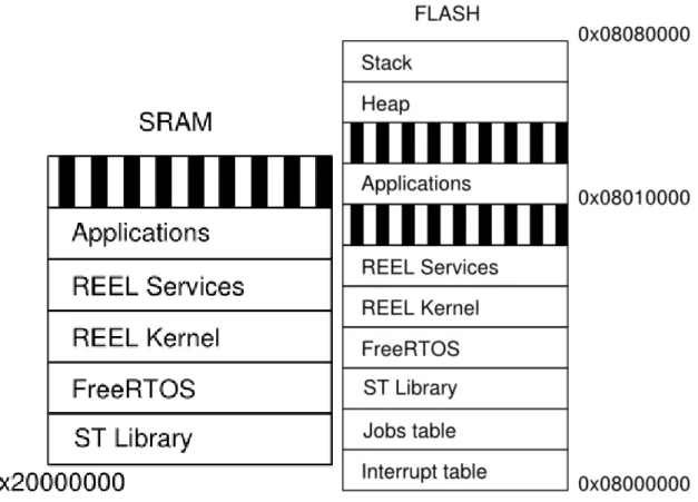
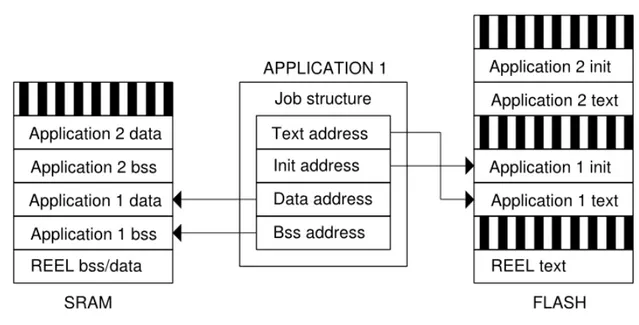
In this section we discuss the behavior of REEL and show the implementation of each components. We preset the hardware platform Netbrick[4] used in this project and a short introduction to FreeRTOS. Over FreeRTOS we realize the REEL service level to implement all the politics and components presented in the Design chapter: Job manager, Remote command interface, Exception manager, Loader service, Boot and restart service. The last section of this chapter presents the mechanism of static linking technique and tools to generate a re-allocable binary file for a REEL application. The figure 4.1 shows the implementation of the designed architecture of REEL into Flash and Sram memories. The layers of the REEL architecture are mapped in different regions in the memories. The size of the system depend on the configuration of FreeRTOS and the ST libraries which we need.
Chapter 4 Implementation
4.1. Kernel space
FreeRTOS is an high configurable real-time operative system. We can choose: • clock of cpu processor Type of task scheduler : preemptive or cooperative. • size of stack memory, name length and property for each task
• schemes of memory allocation
These and other parameters are define in the main FreeRTOS configuration file, “FreeRTOSConfig.h”:
1 #define configUSE_PREEMPTION 1 2 #define configUSE_IDLE_HOOK 1 3 #define configUSE_TICK_HOOK 0
4 #define configCPU_CLOCK_HZ ( 24000000UL )
5 #define configTICK_RATE_HZ ( ( portTickType ) 1000 )
6 #define configMAX_PRIORITIES ( ( unsigned portBASE_TYPE ) 5 ) 7 #define configMINIMAL_STACK_SIZE ( ( unsigned short ) 70 ) 8 #define configTOTAL_HEAP_SIZE ( ( size_t ) ( 7 ú 1024 ) ) 9 #define configMAX_TASK_NAME_LEN ( 10 )
4.1.1. Kernel structure
REEL is based on FreeRTOS. We show the REEL kernel structure as a FreeRTOS program. We can defined four main parts of FreeRTOS program:
1. Includes the FreeRTOS headers (FreeRTOS.h, task.h, list.h, queue.h, FreeR-TOSConfig.h)
2. Declarations of global task handler variables (xJOBMANAGERTaskHandle, xRCITaskHandle)
3. Initialization of components and creation of tasks: we can choose the priority, stack size and function handler for each task.
1 void k e r n e l _ i n i t ( void ) {
2 /ú Component i n i t i a l i z a t i o n ú/
3 EXCEPTIONS_conf( ) ; 4 /ú Tasks creation ú/
5 xTaskCreate ( RCI_start , ( signed char ú) "RCI\0 " ,
APP_TASK_STACK_SIZE/2 , NULL, APP_TASK_PRIORITY, & xRCITaskHandle ) ;
6 xTaskCreate (JOBMANAGER_task, ( signed char ú) "JOB\0 " , APP_TASK_STACK_SIZE/2 , NULL, APP_TASK_PRIORITY, & xJOBMANAGERTaskHandle) ;
7 }
4.2 Reprogramming model
1 void ke rn e l_s ta rt ( void ) { 2 /ú Start the scheduler . ú/
3 vTaskStartScheduler ( ) ;
4 /ú Will only reach here i f there i s i n s u f f i c i e n t heap a v a i l a b l e to s t a r t the s c h e d u l e r . ú/
5 while (1) ;
6 }
4.1.2. FreeRTOS’s tasks
A real time application that uses an RTOS can be structured as a set of independent tasks. Each task executes within its own context with no coincidental dependency on other tasks within the system or the RTOS scheduler itself. Only one task within the application can be executing at any point in time and the real time RTOS scheduler is responsible for deciding which task this should be. As a task has no knowledge of the RTOS scheduler activity it is the responsibility of the real time RTOS scheduler to ensure that the processor context (register values, stack contents, etc) when a task is swapped in is exactly that as when the same task was swapped out. To achieve this each task is provided with its own stack.
A FreeRTOS task can be in one of the following state:
• Running: When a task is actually executing it is said to be in the Running state. It is currently utilizing the processor.
• Ready: Ready tasks are those that are able to execute (they are not blocked or suspended) but are not currently executing because a different task of equal or higher priority is already in the Running state.
• Blocked: A task is said to be in the Blocked state if it is currently waiting for either a temporal or external event.
• Suspended: Tasks in the Suspended state are also not available for scheduling.
4.2. Reprogramming model
The job is a binary program of the user application compiled for the specific tar-get machine that can be transmitted, installed and executed in REEL. The job is compiled for the stm32 platform in the control station with a special procedure to statically reallocate the object code. This special procedure allows the job manager of REEL to execute the native code of an installed job into the WSN node. FreeR-TOS does not support the reallocation procedure to link external binary files: the kernel and the applications are a single monolithic binary file.
Chapter 4 Implementation
4.2.1. Concurrent programming model
REEL is based on FreeRTOS that implements the methods and strategies to execute multiple tasks at the same time by the preemption model. In FreeRTOS a task is a path of program that is independent and is scheduled by OS. Moreover all FreeRTOS tasks have the same properties and does not provide hierarchical mechanism. In other words, an FreeRTOS application is a monolithic binary composed by the kernel and various tasks work independently where each of them is not related to the others. REEL supports the multitasking model as well and extends the concept of multi-Jobs: all tasks of a jobs are executed at the same time. Usually a job is mapped with a single task on FreeRTOS. Moreover a single job can instantiates multiple tasks to cooperate and make a complex work. The multi-task paradigm looks like the multi-threading paradigm in POSIX concurrent programming:
• a job is an executable program for REEL with his own instruction pointer, ad-dress space, memory space, stack and registers. REEL stores meta-information about each jobs in the jobs table, as current state or entry-point.
• a task is a path of execution in a job. Each task has its own instruction pointer, stack and various registers. It shares the same memory space with the job that created the task. All of the tasks in the job share the same global memory, but each task is allocated a chunk of memory for its stack space.
The jobs solution has some others advantages:
• the same time of a normal task because a job for FreeRTOS scheduler is a normal task
• a shared global memory for tasks of the same job
• general functions for group of tasks, when a job begins it starts all child tasks
4.2.2. Job state
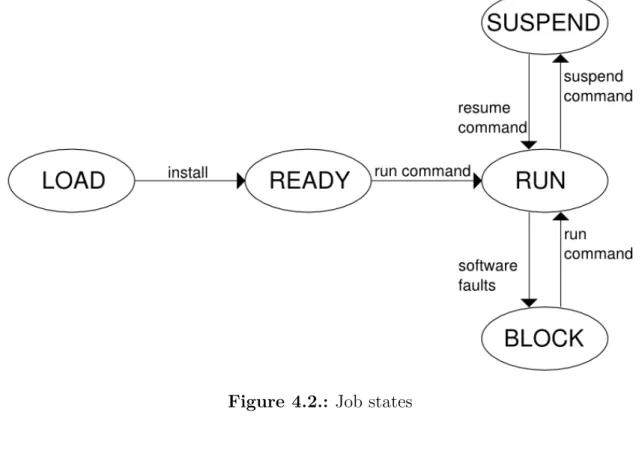
The states of the job are the following:
• load: the job is correctly received but it is not jet installed in the machine • ready: the job is installed in the machine and it is ready to run; the jobs
manager stores the code and data of the job in the memory and sets the meta-information.
• run: the job is executed; all the tasks of the job are scheduled. At boot time, the job is started.
• suspend: the execution of the job is suspended by the user; all the task of the job are delete from the scheduler. At boot time, the job is restarted.
• block: the execution of the task is stopped by a fault. If only one task gets a fault, all tasks of the job are suspended. At boot time, the job is not started.
4.2 Reprogramming model
The status information is useful in the reset phase when the boot loader looks the application table and starts only the jobs marked as RUN.
Figure 4.2.: Job states
4.2.3. Job structure
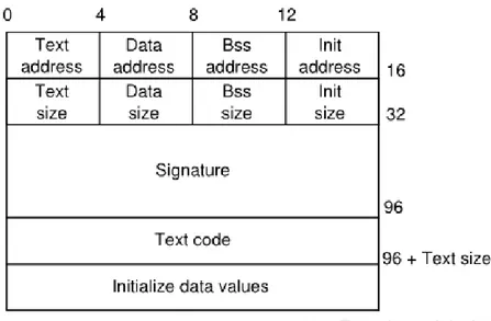
The main meta information associated to a job are the following:
• size and started address of code and init sections on FLASH memory. • size and started address of data and bss sections on SRAM memory. • the list of tasks of the job.
• the current state of a job. In the following we present the complete structure of a job. 1 struct job_t { 2 uint8_t id ; 3 uint32_t size_text ; 4 uint32_t size_data ; 5 uint32_t size_bss ; 6 uint32_t s i z e _ i n i t ; 7 uint8_t s i g n a t u r e [SIGNATURE_SIZE ] ; 8 uint8_t ú text ; 9 uint8_t ú i n i t ; 10 uint8_t údata ; 11 uint8_t ú bss ;
Chapter 4 Implementation
12 Jobstate s t a t e ; 13 xTaskHandle task ;
14 xTaskHandle ú taskChild [MAX_TASK_FOR_JOB] ; 15 } ;
16 typedef struct job_t Job ;
Figure 4.3.: Job structure and memory addressing
4.3. Jobs manager
The high-level application for REEL framework, called Job, is a program develop by the user and executed by REEL. Basically it looks as a normal program written in C with ST library methods and FreeRTOS functions. REEL wants to improve the ex-ecution paradigm of concurrent programming and extend the concept of FreeRTOS task. In REEL a job is:
• the binary file of the application that can be transmitted, installed and exe-cuted in REEL framework.
• the hierarchical multi-tasks execution model for concurrent programming The jobs manager component implements all the mechanisms to manage a job on the device. For this purpose the jobs manager stores information about the memory location, the execute status and the some error status for each jobs. These meta-information form the list of jobs stored in a global structure called JobsTable.
4.3.1. Jobs table
The JobsTable is the list of all jobs installed on the machine. This is a critical resource for two reason:
4.3 Jobs manager
• It can be accessible in writing only by task in the kernel space.
• The values must not change after a reset In the REEL the JobsTable resides in the initial regions of the FLASH memory after the Interrupt Vector. REEL allocates 2kB of FLASH, 16 job-entries, for the JobsTable because 2kB is the minimum block writable by the FLASH.
In other words, REEL standard configuration support at max 6 installed jobs. For performance in SRAM there is a copy of the JobsTable for local update.
1 static Job JOBMANAGER_table_FLASH[JOBTABLE_SIZE] __attribute__ ( ( s e c t i o n ( " j o b t a b l e " ) ) ) ;
We present two solution for the implementation of the Jobstable:
• centralized: store all the meta information in a single location in memory. • distributed: each job contains his meta information in his part of memory
assigned.
The reason of the choice is imposed by hardware constrains. In this implementation we used a centralized job table.
4.3.1.1. Centralized approach
The system allocates one block of the FLASH memory for the job table structure. In the STM32 architecture a block of memory is composed by 2k of bytes. In one hand, all the information about the current status of the entire system are in a single place and we don’t need scan the memory to find meta information. In the other hand, the entire block of memory must be rewritten each time that we want to modify the status of a job or insert/delete a job. So we need a buffer of dimension of one memory block.
4.3.1.2. Distributed approach
The distributed solution is based on the idea that each job stores his meta infor-mation in his segment of memory. At startup the boot loader scans each segment of memory and retrieves the value of the information. We save memory because we don’t use a block of memory for the table and a buffer as in centralized case. In the other hand, a change in the job state field brings the rewriting of all the job memory; this is not want we want.
In the simplest scenario, the system knows only the running jobs. If an application has faults or does not work anymore, it is clear from the system. In this way, the system does not need the byte for the jobs status. So a single row in the job table has read-only access. This solution is the perfect case for a distributed job table where each job contains his own meta information which a read-only access.
Chapter 4 Implementation
4.3.2. Jobs operations
List of functions to scan, insert or delete jobs from the JobsTable:
• JOBMANAGER_task: scan the JobsTable and schedule the jobs to execute at restart.
1 void JOBMANAGER_task( void ) {
2 //Copy the s t r u c t u r e from FLASH to SRAM
3 FLASH_readPage ( ( uint32_t )JOBMANAGER_table_FLASH, ( uint32_t ) JOBMANAGER_table_SRAM) ;
4 uint8_t i ;
5 for ( i =0; i<JOBTABLE_SIZE; i++){
6 i f (JOBMANAGER_table_SRAM[ i ] . id !=0) { 7 switch (JOBMANAGER_table_SRAM[ i ] . s t a t e ) { 8 case BLOCK: 9 break ; 10 case READY: 11 JOBMANAGER_table_SRAM[ i ] . s t a t e=LOAD; 12 JOBMANAGER_ready(&JOBMANAGER_table_SRAM[ i ] ) ; 13 break ; 14 case RUN: 15 JOBMANAGER_table_SRAM[ i ] . s t a t e=LOAD; 16 JOBMANAGER_ready(&JOBMANAGER_table_SRAM[ i ] ) ; 17 JOBMANAGER_resume(&JOBMANAGER_table_SRAM[ i ] ) ; 18 break ; 19 case SUSPEND: 20 JOBMANAGER_table_SRAM[ i ] . s t a t e=LOAD; 21 JOBMANAGER_ready(&JOBMANAGER_table_SRAM[ i ] ) ; 22 JOBMANAGER_suspend(&JOBMANAGER_table_SRAM[ i ] ) ; 23 break ; 24 default : 25 break ; 26 } 27 } 28 } 29 }
• JOBMANAGER_save: copy the volatile jobtable from SRAM to FLASH • JOBMANAGER_create: assign a slot to a job in the jobtable
• JOBMANAGER_free: search a free slot in the jobtable • JOBMANAGER_get: return the pointer to a job from his id
• JOBMANAGER_lookUpTask: return the pointer to a job from his task • JOBMANAGER_index: return the position of a job in the jobtable • JOBMANAGER_delete: clear a job
![Figure 2.2.: The memory architecture of the Contiki memory [7].](https://thumb-eu.123doks.com/thumbv2/123dokorg/7524759.106389/27.892.209.655.111.403/figure-memory-architecture-contiki-memory.webp)
![Figure 2.3.: The dynamic linking mechanism of Contiki [7]](https://thumb-eu.123doks.com/thumbv2/123dokorg/7524759.106389/28.892.289.622.402.711/figure-dynamic-linking-mechanism-contiki.webp)