Advanced Techniques for Future
Multicarrier Systems
Dipartimento di Ingegneria dell’Informazione: Elettronica, Informatica e Telecomunicazioni
Universit`a di Pisa
A thesis submitted for the degree of Dottore di Ricerca in Ingegneria dell’Informazione
January 2011
Author: Advisors:
Ing. Giulio Dainelli Prof. Aldo Nunzio D’Andrea
Ing. Marco Moretti Prof. Michele Morelli
Acknowledgements
First of all I would like to thank my advisor, Marco Moretti, for his support. His help was crucial for my professional and personal growth. I have gained from his ex-traordinary motivation, great intuition and technical insight. Thanks to my other advisors, Professors Aldo D’Andrea and Michele Morelli, who have always been available when I needed them. I would also like to thank Professor Ruggero Reg-giannini, with whom I had the fortune to work and collaborate. A special thanks goes to Alfredo Todini, for his invaluable advice and his constant availability. Many thanks to my friends and colleagues of the Department of Information Engi-neering at the University of Pisa for their countless discussions and for a pleasant working atmosphere. I will always be indebted to my colleagues and friends of the Transmission Research Group for their helpful technical insights and valuable hints over these three years. Among these, Lorenzo Taponecco and Luca Sanguinetti have always been ready to listen to me and to have some fun together.
I would like to thank my parents for believing in me and for the sacrifices they made to get me here. If have written this thesis, a lot is due to them.
Finally, thanks to the most important person in my life, my wife Ilaria. I love you.
Future multicarrier systems face the tough challenge of supporting high data-rate and high-quality services. The main limitation is the frequency-selective nature of the propagation channel that affects the received signal, thus degrading the system performance.
OFDM can be envisaged as one of the most promising modulation techniques for future communication systems. It exhibits robustness to ISI even in very dispersive environments and its main characteristic is to take advantage of channel diversity by performing dynamic resource allocation. In a multi-user OFDMA scenario, the challenge is to allocate, on the basis of the channel knowledge, different portions of the available frequency spectrum among the users in the systems.
Literature on resource allocation for OFDMA systems mainly focused on single-cell systems, where the objective is to assign subcarriers, power and data-rate for each user according to a predetermined criterion. The problem can be formulated with the goal of either maximizing the system sum-rate subject to a constraint on transmitted power or minimizing the overall power consumption under some prede-termined constraints on rate per user. Only recently, literature focuses on resource allocation in multi-cell networks, where the goal is not only to take advantage of frequency and multi-user diversity, but also to mitigate MAI, which represents one of the most limiting factor for such problems.
We consider a multi-cell OFDMA system with frequency reuse distance equal to one. Allowing all cells to transmit on the whole bandwidth unveils large potential gains in terms of spectral efficiency in comparison with conventional cellular systems. Such a scenario, however, is often deemed unfeasible because of the strong MAI that negatively affects the system performance. In this dissertation we present a layered architecture that integrates a packet scheduler with an adaptive resource allocator, explicitly designed to take care of the multiple access interference. Each
cell performs its resource management in a distributed way without any central controller. Iterative resource allocation assigns radio channels to the users so as to minimize the interference. Packet scheduling guarantees that all users get a fair share of resources regardless of their position in the cell. This scheduler-allocator architecture integrates both goals and is able to self adapt to any traffic and user configuration. An adaptive, distributed load control strategy can reduce the cell load so that the iterative procedure always converges to a stable allocation, regardless of the interference. Numerical results show that the proposed architecture guarantees both high spectral efficiency and throughput fairness among flows.
In the second part of this dissertation we deal with FBMC communication sys-tems. FBMC modulation is a valid alternative to conventional OFDM signaling as it presents a set of appealing characteristics, such as robustness to narrowband inter-ferers, more flexibility to allocate groups of subchannels to different users/services, and frequency-domain equalization without any cyclic extension. However, like any other multicarrier modulations, FBMC is strongly affected by residual CFOs that have to be accurately estimated.
Unlike previously proposed algorithms, whereby frequency is recovered either rely-ing on known pilot symbols multiplexed with the data stream or exploitrely-ing specific properties of the multicarrier signal structure in following a blind approach, we present and discuss an algorithm based on the ML principle, which takes advantage both of pilot symbols and also indirectly of data symbols through knowledge and exploitation of their specific modulation format. The algorithm requires the avail-ability of the statistical properties of channel fading up to second-order moments. It is shown that the above approach allows to improve on both frequency acquisition range and estimation accuracy of previously published schemes.
Contents
Notation vii
Acronyms ix
List of Figures xiii
1 Introduction 1
1.1 Outline of Dissertation . . . 4
2 Multicarrier modulation techniques 5 2.1 OFDM . . . 6 2.1.1 Transmitter structure . . . 6 2.1.2 Receiver structure . . . 7 2.2 FBMC . . . 9 2.2.1 Transmitter structure . . . 9 2.2.2 Receiver structure . . . 11
3 Resource allocation in single cell OFDMA systems 13 3.1 Resource allocation in single-user OFDM systems . . . 14
3.1.1 The water-filling algorithm . . . 16
3.2 Multi-user OFDM systems . . . 18
3.2.1 Multi-user RA algorithms . . . 21
3.2.1.1 Multi-user RA with fairness . . . 23
3.2.1.2 Numerical results . . . 26
3.2.2 Multi-user MA schemes . . . 28
3.2.2.2 Numerical results . . . 32
4 Resource allocation in multi-cell OFDMA systems 35 4.1 System model and problem formulation . . . 37
4.2 Distributed layered allocation architecture . . . 39
4.2.1 Single-cell radio resource allocation based on linear programming . . . 39
4.2.2 Load control . . . 43
4.2.3 Credit-based packet scheduling . . . 46
4.3 A centralized allocator for multicellular multi-carrier systems . . . 48
4.4 Numerical Results . . . 50
5 Carrier frequency offset recovery in FBMC systems 59 5.1 Signal Model . . . 61
5.2 ML Carrier Frequency Estimation . . . 63
5.2.1 Formulation of the ML Estimation Problem . . . 63
5.2.2 Combined Pilot-Aided and Decision-Directed Frequency Estimation . . . 64
5.3 Cramer-Rao Lower Bound for PA-MLE . . . 66
5.4 Performance Results . . . 67
5.4.1 Simulation Setup . . . 67
5.4.2 MSEE Performance . . . 68
Bibliography 71
Notation
(·)T denotes transpose operation (·)H denotes Hermitian transposition
[·]k,ℓ denotes the (k, ℓ)th entry of the enclosed matrix (x)+ denotes the maximum between x and 0
∥ · ∥ denotes the Euclidean norm tr{ · } denotes the trace of a matrix
IN denotes the identity matrix of order N
card{·} denotes the cardinality of the enclosed set E{·} denotes the expectation operator
M−1 denotes the inverse of a square matrix M
Re{·} denotes the real part of a complex-valued quantity Im{·} denotes the imaginary parts of a complex-valued quantity |·| denotes the magnitude a complex-valued quantity
Acronyms
3GPP Third Generation Partnership Project
AMC Adaptive Modulation and Coding
AWGN Additive White Gaussian Noise
BER Bit Error Rate
BS Base Station
CBFQ Credit-Based Fair Queueing
CDMA Code Division Multiple Access
CFO Carrier Frequency Offset
CMLE Combined Maximum Likelihood Estimator
CP Cyclic Prefix
CRA Centralized Multi-format Resource Allocator
CRLB Cramer-Rao Lower Bound
CSI Channel State Information
D/A Digital-to-Analog
DA Data-Aided
DD Decision Directed
DFT Discrete Fourier Transform
DLA Dynamic Layered Architecture
DVB Digital Video Broadcasting
EVD Eigenvalue Decomposition
FBMC Filter Bank Multicarrier
FFR Fractional Frequency Reuse
FF Fast-Fading
ICI Inter Carrier Interference
IDFT Inverse Discrete Fourier Transform
IPM Interior Point Method
ISI Inter Symbol Interference
JMLE Joint Maximum Likelihood Estimator
LC- CMLE Low Complexity Combined Maximum Likelihood Estimator
LC Load Control
LIP Linear Integer Programming
LLF Log-Likelihood Function
LP Linear Programming
LTE Long Term Evolution
MAC Media Access Control
MAI Multiple Access Interference
MARA Multi-Assign Resource Allocator
MA Margin Adaptive
MLE Maximum Likelihood Estimator
ML Maximum Likelihood
MSEE Mean Square Estimation Error
MS Mobile Station
NP Non-deterministic Polynomial time
NSM Network Simplex Method
OFDMA Orthogonal Frequency Division Multiple-Access OFDM Orthogonal Frequency Division Multiplexing
PA Pilot-Aided
PSK Phase Shift Keying
PS Packet Scheduler
QAM Quadrature Amplitude Modulation
RA Rate Adaptive
RNC Radio Network Controller
RRA Radio Resource Allocator
SF Slow-Fading
SINR Signal to Interference plus Noise Ratio
SRRC Square Root Raised Cosine
TETRA Terrestrial Trunked Radio
TTI Transmission Time Interval
TU Typical Urban
UTRAN Universal Terrestrial Radio Access Network Wi-MAX Worldwide Interoperability for Microwave Access
List of Figures
2.1 Channel frequency response. In multicarrier system each information-bearing
symbol undergoes frequency flat fading channel. . . 6
2.2 Block diagram of an OFDM transmitter. . . 7
2.3 Block diagram of an OFDM receiver. . . 8
2.4 Block diagram of an FBMC transmission systems. . . 10
3.1 Water-filling . . . 17
3.2 BS transmitter for OFDMA downlink transmission with adaptive resource allo-cation . . . 19
3.3 k-th user receiver for OFDMA downlink transmission with adaptive resource allocation . . . 19
3.4 Fairness vs. number of users . . . 27
3.5 Throughput vs. number of users . . . 28
3.6 Mean transmitted power Pm vs. spectral efficiency η . . . . 33
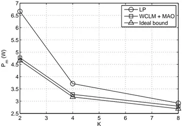
3.7 Mean transmitted power Pm vs. number of users K . . . . 34
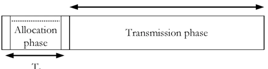
4.1 Frame structure . . . 37
4.2 Measured spectral efficiency ηm vs. duration of allocation phase Ns. . . 51
4.3 Mean power per cell Pmvs. duration of allocation phase Ns . . . 52
4.4 Measured spectral efficiency ηm vs. target spectral efficiency η (resource alloca-tion and load control, no scheduler, same rate for all users) . . . 53
4.5 Mean power per cell Pmvs. measured spectral efficiency ηm(resource allocation and load control, no scheduler, same rate for all users) . . . 54
4.6 Measured spectral efficiency ηm vs. target spectral efficiency η (resource alloca-tion and load control, no scheduler, same rate for all users) . . . 55
4.7 Mean power per cell Pm vs. number of users K (resource allocation and load
control, no scheduler, same rate for all users) . . . 55
4.8 Measured spectral efficiency ηm vs. target spectral efficiency (Distributed Lay-ered Architecture) . . . 56
4.9 Jain’s fairness index per cell vs. frame . . . 57
5.1 Acquisition range on slow-fading channel at Es/N0= 30 dB. . . 68
5.2 Acquisition range on fast-fading channel at Es/N0= 30 dB. . . 68
5.3 MSEE versus Es/N0 on slow-fading channel. . . 69
Chapter 1
Introduction
The rapid growth of wireless communications in the recent past has modified the way of com-municating with each other. Digital cellular phones, as well as portable computer and fixed Internet technologies have contributed to the increase of wireless internet access. In many cases, such as in homes, offices and small urban areas, wireless local area networks have sub-stituted wired networks. Many new applications, e.g. smart phones, wireless sensor networks, have been derived from research environments and produced in real systems. From the infras-tructure point of view, the design of robust wireless communication network for each of these emerging applications represents the major challenge.
Future wireless communication systems will provide wideband access to large numbers of subscribers, while fulfilling at the same time strong requirements in terms of QoS. The challenge arises from the scarcity of frequency spectrum, the limitation on total transmit power and the nature of wireless channel. In wireless communications, the transmitted signals pass through a wireless propagation channel which is affected by frequency-selectivity and multipath fading, deriving from scattering, reflection, and diffraction of the radiated energy by objects in the environment or refraction in the medium. At the receiver side, the signal is the combination of different replicas of the original transmitted signal over each path. This leads to fluctuation of power of the received signal because of the constructive or destructive combination of the mul-tipath components. Moreover, if the transmitter, receiver or surrounding objects are moving, the characteristic of the channel could change randomly. This leads to severe ISI both in time and frequency, thus degrading the data rate of communication. Dynamic resource allocation schemes that interact in both in the physical and the MAC layers are necessary to combat ISI.
The idea is to allocate system resources (i.e. subcarriers, power and bit rate) to the users in the system according to the changing conditions of wireless propagation environment in order to achieve large gains in terms of the system capacity.
OFDM is one of the promising solutions to provide high performance from a physical layer point of view and it has been adopted in several standards, e.g. IEEE 802.11 (WLANs) [1], IEEE 802.16 (Wi-MAX) [2] and 3GPP LTE [3]. OFDM divides the whole bandwidth into N orthogonal narrowband subchannels, each with a bandwidth smaller than the coherence bandwidth of the channel. The stream at high data rate is split into N substreams with lower data rate, thus the N OFDM sysmbols are transmitted simultaneously on N orthogonal subcarriers. During each transmission block, each orthogonal subchannel can be approximated as a flat fading channel with constant channel gain. Provided that the system parameters are accurately dimensioned, OFDM transmissions are not affected by ISI even in highly frequency-selective channels [4].
Several studies have shown that in a single-user system large gains in terms of system performance are given by employing dynamic resource allocation algorithms, as compared to static allocation schemes. The goal is to select the best set of modulation parameters for each subcarrier so as either to maximize the overall data throughput under a constraint on total transmitted power or to minimize the overall transmit power given a fixed throughput.
In a multiuser scenario, the problem of resource allocation arises from the need for a multiple access scheme in which users share the same bandwidth. In static allocation schemes, each user receives predetermined time slots or frequency channels respectively without considering their channel conditions. The problem reduces to only power allocation on the subcarriers. However, since the fading parameters for different users are mutually independent, the probability that a subcarrier is in deep fade for all users is very low. Thus, in an OFDMA system where each user is assigned a different subset of the available bandwidth, assuming that the transmitter has perfect knowledge of CSI for each user, subcarriers can be assigned according to a predetermined optimization criterion so as to increase the system spectral efficiency.
Most of the existing literature focuses on the single-cell scenario, either formulating the problem with the goal of maximizing the system sum rate subject to a limitation on power con-sumption, or aiming at minimizing the overall transmit power subject to users’ rate constraints. Only recently, the problem of resource allocation in multi-cell networks has been addressed. In multi-cell environments, resource allocation is also helpful in reducing MAI from neighboring cells, thus making possible the development of a cluster with full reuse of the frequency
spec-trum. Unfortunately, the complexity of the allocation problem is extremely demanding and also, due to the detrimental effect of the MAI, the solution may not exist.
Among multicarrier modulation techniques, a valid alternative to conventional OFDM sig-naling is represented by FBMC modulations initially proposed for very high-speed wired access networks. In FBMC transmissions data symbols are frequency-multiplexed over contiguous subchannels after proper pulse shaping [5]. Compared to OFDM modulation, pulses are signifi-cantly longer than the subchannel symbol spacing, and thus overlap in time. Conversely, signal spectra on the subcarriers are band-limited and, depending on the shaping filter employed in the transmission filter bank, they can be either non-overlapping in frequency or marginally over-lapping as in [6]. As a result, FBMC can be envisaged as an efficient alternative to conventional OFDM with a number of attractive features, such as i ) lesser sensitivity to narrowband inter-ferers, ii ) higher flexibility to allocate groups of subchannels to different users, iii ) mitigation of ICI on severely time-frequency selective channels, iv ) simpler frequency domain equalization not requiring any cyclic extension. The above qualities explain why FBMC schemes have been adopted as well for a number of wireless standards, such as the return channel of terrestrial DVB (DVB-RCT) [7] and the 2ndrelease of the TETRA air interface [8].
Like any other multicarrier transmission schemes, FBMC is strongly sensitive to residual CFOs, which must be accurately estimated and removed from the received waveform prior to channel estimation and data decoding. The issue of CFO recovery for multicarrier systems has received considerable attention in recent literature, but unfortunately the proposed techniques are primarily intended for OFDM and are neither optimized nor directly applicable to FBMC in view of the rather different signal formats. Until now, only a few algorithms for CFO extraction specifically tailored for FBMC have been proposed. In addition, they are devised under the assumption of time-invariant or slowly changing fading and as such they exhibit poor behavior whenever the channel is affected by a significant Doppler spread.
In this dissertation we also deal with FBMC communications and we propose a novel CFO recovery algorithm that, rather than either relying on known pilot symbols multiplexed within the transmitted burst or exploiting the specific signal structure in a blind mode, takes advantage of both pilot symbols and also indirectly of the data symbols through differential decisions. We will show that, when compared to conventional pilot-based methods, the proposed approach improves the frequency acquisition range without degrading accuracy, while retaining approxi-mately the same computational load.
1.1
Outline of Dissertation
The outline of the dissertation is as follows.
The present Chapter introduces the motivations and summarizes the structure of this dis-sertation.
Chapter 2 provides the basic concepts of OFDM and FBMC systems.
In Chapter 3, in order to introduce and discuss the main contribution of this dissertation, we briefly revise the well-known resource allocation algorithms for single-cell OFDMA systems. Chapter 4 analyzes and discusses the performance of a resource allocation scheme for an OFDMA multi-cell system. We design a layered architecture that integrates a packet scheduler and an adaptive resource allocator with the goal of mitigating the multiple access interference. This architecture is able to assign radio channels to the users so as to minimize interference, as well as to guarantee a fair number of resources to each user in the system.
In Chapter 5 we deal with FBMC systems and develop an algorithm for the recovery of the CFO over time-frequency selective fading channels. The algorithm we derive is based on the ML principle and takes advantages of both pilot symbols and also indirectly of the data symbols through differential decisions.
Chapter 2
Multicarrier modulation
techniques
We pointed out that in frequency-selective fading channels the received signal is typically af-fected by ISI. The classical approach adopted in single carrier systems is time-domain equaliza-tion. However, the number of operations per signaling interval grows linearly with the number of interfering symbols or, equivalently, with the data rate. As a result, conventional time-domain equalizers are not suitable for high-speed transmissions with channel delay spreads extending over tens of symbol intervals. This has motivated the adoption of multicarrier modulations as a computationally efficient alternative for facing with the severe impairments of multipath propagation. The idea behind multicarrier modulations is to split a high-rate data stream into a number of low-rate streams which are transmitted in parallel on adjacent subchannels. As is shown in Figure2.1, reducing the data rate or, equivalently, increasing the symbol duration, makes the frequency selective fading channel appear flat on each subcarrier, thereby limiting the ISI.
In the next, we briefly revise the system structure of these two multicarrier technologies, such as OFDM and FBMC, which have been adopted by several standards for next generation communication systems.
C ha nn el fre qu en cy res po ns e Frequency C ha nn el fre qu en cy res po ns e Frequency
Figure 2.1: Channel frequency response. In multicarrier system each information-bearing symbol undergoes frequency flat fading channel.
2.1
OFDM
OFDM is a multiplexing technique in which a high data rate stream is split into N subflows with lower data rate and the N OFDM symbols are transmitted simultaneously over the N orthogo-nal subcarriers. Compared with single-carrier multiple-access systems, OFDM offers increased robustness to narrowband interference and does not need adaptive time-domain equalizers, since channel equalization is performed in the frequency domain through one-tap multipliers. The combination of OFDM with a dynamic channel assignment algorithm allows the system to increase its performance in terms of capacity.
This technique was originally implemented using a bank of Nyquist filters which provide a set of continuous-time orthogonal basis functions. Using very fast and cost effective digital signal processors, OFDM modulation is now implemented using DFT techniques. This has motivated the adoption of OFDMA as a standard for the WLAN IEEE 802.11a, Wi-MAX 802.16 and it has also been proposed for digital cable television systems.
2.1.1
Transmitter structure
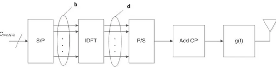
The block diagram of the transmitter is shown in Figure2.2. The complex symbols cibelonging to an M -QAM or M -PSK constellation with average energy σ2
c are characterized by a signaling rate R = 1/T . These symbols are fed to a serial-to-parallel converter, where each flow has a signaling time Ts= N T , which is referred to as OFDM symbol time. In the figure, the index n (n = 1, . . . , N ) denotes the subcarrier, while m is the index for an OFDM symbol with rate 1/Ts = (1/T )/N . Thus, the N symbols at the output of the serial-to-parallel converter are
2.1 OFDM
Figure 2.2: Block diagram of an OFDM transmitter.
sent to an OFDM modulator, which comprises an N -point IDFT unit and the insertion of an NG-point CP larger than the channel impulse response. The CP serves to eliminate inter-block interference and makes the linear convolution of the symbols with the channel look like a circular convolution, which is essential for demodulation based on DFT. This produces an (N + NG )-dimensional vector d = [d(−NG), d(−NG+ 1), . . . , d(N− 1)]
T
of time domain samples where d(n) = d(n + N ) for−NG≤ n ≤ −1 and d(n) = N ∑ ℓ=1 b(ℓ)e−j2πℓnN, 0≤ n ≤ N − 1, (2.1)
where bℓ= c0(ℓ) are the transmitted symbols on the first OFDM symbol.
The resulting vector d is finally passed to a D/A converter with impulse response g(t) and signalling interval Ts. The complex envelope of the signal transmitted takes the form
s(t) = N∑−1 n=−NG
d(n)g(t− nTs) (2.2)
where g(t) has a root-raised cosine Fourier transform with some roll-off α.
2.1.2
Receiver structure
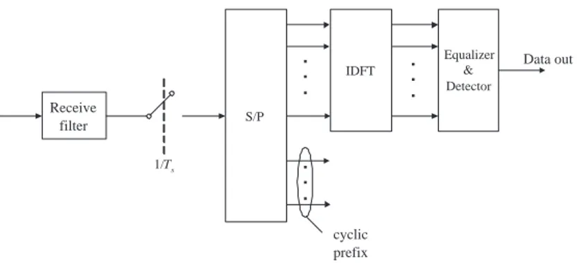
Figure 2.3illustrates the block diagram of an OFDM receiver. At the receiver, the incoming waveform is first filtered and then sampled at rate 1/Ts= 1/(N T ) . This produces
x(n) = N∑−1 ℓ=−NG
d(ℓ)h(n− ℓ) + w(n) (2.3)
where w(n) is thermal noise and h(n) is the sample of the overall channel impulse response h(t) (including the physical channel, the shaping pulse at the transmitter and the whitening matched filter at the receiver) at time t = nTs. Statistical models for the channel impulse response of a fading multipath channel have been described in details in literature over the past
.
.
.
.
.
.
Receive filter S/P IDFT.
.
.
.
.
.
Equalizer & Detector Data out cyclic prefix 1/TsFigure 2.3: Block diagram of an OFDM receiver.
years. Since its out of the scope of this work to provide a description of such models, we refer to some excellent references on this field such as [9]-[10].
After discarding the CP and using a matrix notation, the samples at the output of the matched filter can be expressed as follows
x(0) x(1) .. . x(N − 1) = h(0) 0 · · · · · · 0 h(L) · · · h(1) .. . . .. . .. 0 . .. ... .. . h(0) . .. . .. h(L) h(L) ... . .. 0 0 0 . .. ... h(0) . .. ... .. . . .. h(L) ... . .. . .. ... .. . . .. . .. ... . .. 0 0 · · · · · · 0 h(L) · · · · · · h(0) d(0) d(1) .. . d(N− 1) (2.4)
where L is the length in sampling periods of the channel impulse response. Inspections of the above equation reveals that thanks to the introduction of the CP at the transmitter and its removal at the receiver, the resulting time domain samples are related to the input data symbols through the channel matrix in (2.4). The latter is a circulant matrix, i.e., its rows are composed of cyclically shifted versions of a given sequence [11]. In other words, the effect of the cyclic prefix is to make the channel look like circular convolution instead of linear convolution, thereby completely removing the ISI.
From matrix theory it turns out that these kind of matrices have a very interesting and useful property [12]. The eigenvectors are independent of the specific channel coefficients and are always given by complex exponentials. To be more precise, the EVD of the circulant channel
2.2 FBMC matrix in (2.4) is h(0) 0 · · · · · · 0 h(L) · · · h(1) .. . . .. . .. 0 . .. ... .. . h(0) . .. . .. h(L) h(L) ... . .. 0 0 0 . .. ... h(0) . .. ... .. . . .. h(L) ... . .. . .. ... .. . . .. . .. ... . .. 0 0 · · · · · · 0 h(L) · · · · · · h(0) = FHHF (2.5)
where F is the N× N unitary DFT matrix whose entries are given by
[F]n,ℓ= e−j2π nℓ/N 0≤ n ≤ N − 1 , 0≤ ℓ ≤ N − 1. (2.6) while H = diag{H(0), H(1), . . . , H(N − 1)} is N × N diagonal matrix with
H(n) = L∑−1 ℓ=0
h(ℓ)e−j2πℓnN. (2.7)
Collecting the above fact together, we see that at the receiver the DFT outputs y(n) for n = 0, 1, . . . , N− 1 can be written as
y(n) = H(n)s(n) + w(n) (2.8) or in matrix notation
y = Hs + w. (2.9)
From the above equation it follows that thanks to the multicarrier approach, the original frequency-selective channel with inter-symbol and inter-block interference is transformed into a set of parallel flat subchannels, which can be straightforwardly equalized at receiver side using a simple bank of one-tap multipliers.
2.2
FBMC
2.2.1
Transmitter structure
In FBMC-based systems, the data symbols are transmitted over different subchannels after suitable pulse shaping. Unlike OFDM, the pulse waveforms associated to different symbols
overlap in time, As a result of pulse shaping, the spectra of the data signals on the different subcarriers are bandlimited, while preserving orthogonality amongst subcarriers in spite of time overlap.
Let us assume that the source M -QAM data symbols a(q)ℓ (at the rate N/T ) are grouped into blocks of size N , the symbol q being the index of the symbol within each block (1≤ q ≤ N) and is also the subcarrier index after MC modulation. Each subcarrier is shaped by means of a conventional SRRC filter with impulse response g(t) and roll-off ξ and a signaling interval T . In order to prevent spectral overlap, each subcarrier is centered at frequency q(1+ξ)/T . Assuming that the quantity M = (1 + ξ)N is an integer, the transmitted signal can be expressed as
s(t) =∑ ℓ N ∑ q=1 a(q)ℓ g(t− ℓT )ej2πqM t/N T. (2.10)
In a digital implementation of the modulator using the sampling frequency fs= 1/Ts= M/T , the digitized FBMC signal is thus
s(m)h , s((Mh + m)Ts) = ∑ ℓ N ∑ q=1 a(q)ℓ g[M (h− ℓ) + m]ej2πq(M h+ℓ)/N, (2.11)
where we adopt a polyphase decomposition for the time index of the i-th sampling instant ti = (M h + m)Ts, 1≤ m ≤ M and h some integer, and g[ℓ] , g(ℓTs).
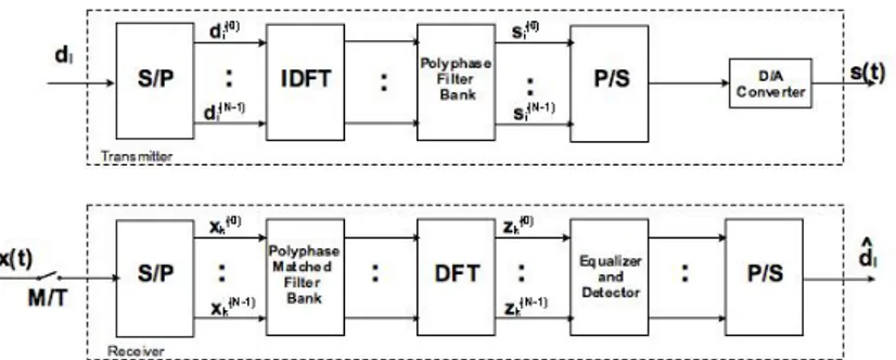
Figure 2.4: Block diagram of an FBMC transmission systems.
Figure 2.4 shows the FBMC transmission system, which comprises an OFDM modulator followed by a bank of polyphase filter. The ℓ-th N symbol block are fed to an IDFT, where each element of the parallel IDFT output is processed at the rate 1/T by a different filter (the filterbank ) whose impulse response gT(m)[ℓ] is obtained by the polyphase decomposition of the prototype SRRC filter gT(m)[ℓ] = g ( ℓT +mT M ) = g(ℓM Ts+ mTs), 1≤ m ≤ M. (2.12)
2.2 FBMC
The samples obtained at the output of the filter bank are then rearranged and D/A converted to produce the time-continuous FBMC signal (2.10). It is worth pointing out that the number of filters is M (with M being the number of signal samples to be computed in every block of N source symbols), while the number of IDFT outputs is N (i.e., the number of subcarriers). Thereby, the filterbank gT(m)[ℓ] also contains a suitable signal memory that feeds the diverse filters of the bank with appropriately permuted versions of the IDFT outputs [5].
2.2.2
Receiver structure
Let us assume that the propagation channel is selective in time and frequency with impulse response c(t) = U ∑ u=1 ρu(t)δ(t− τu), (2.13)
where U is the number of paths, while ρu(t) and τuare the time-varying complex gains and the delays of each path, respectively. Then, the received signal can be expressed by
r(t) = U ∑ u=1 ∑ ℓ N ∑ q=1 ρu(t)a (q) ℓ g(t− ℓT − τu)ej2πqM t/N T · e−j2πqMτu/N Tej2πνt/Tejθ+ n(t), (2.14)
where ν is the frequency offset normalized to the signaling rate 1/T , θ is the phase offset and n(t) is the AWGN with two-sided power spectral density 2N0.
In the lower part of Figure 2.4 it is shown the implementation of FBMC receiver. The samples are taken at rate M/T and processed by the receiver polyphase filterbank (i.e., receiver matched filter) and the DFT unit. Then, data detection is performed after channel equalization [5], [13]. The output of the DFT corresponding to the n-th subcarrier at the instant t = kT is given by zk(n)= U ∑ u=1 ∑ ℓ N ∑ q=1 a(q)ℓ A(n,q)k,ℓ,u(ν)ejθ+ w(n)k , (2.15)
where wk(n)is a zero-mean independent Gaussian random variable with variance σ2= 2N 0and A(n,q)k,ℓ,u(ν), e−j2πqMτu/N T ∫ +∞ −∞ ρu(t)g(t− ℓT − τu) · g(t − kT )ej2π(q−n)Mt/NTej2πνt/Tdt (2.16)
is a complex-valued factor accounting for the contribution to the sample (2.15) of the ℓ-th symbol on the q-th subcarrier propagating over the u-th path in the presence of the frequency offset ν.
Assume that within a time ∆t comparable with the non-zero support of g(t) (namely, a few FBMC symbol intervals) the following assumptions hold: i) the fading process does not change significantly; ii) the frequency offset is small enough so that ej2π∆t/T ≈ 1; iii) the delay spread of the channel is significantly shorter than the FBMC signaling interval. More in detail, assumptions i) and ii) allow us to consider as orthogonal the signals on different subchannels, while assumption iii) implies that the channel delay spread does not destroy the orthogonality of the consecutive symbols on the same subcarrier, i.e., the ISI on each subcarrier is negligible.
Based on this discussion, we can simplify the (2.16) as follows
A(n,q)k,ℓ,u(ν)≃ ρu(kt)e−j2πqMτu/N Tej2πνt/T, q = n, ℓ = k 0, otherwise (2.17)
thereby, (2.15) can be approximated as
zk(n)≃ φ(n)k a(n)k ej2πνkejθ+ wk(n), (2.18) where φ(n)k = U ∑ u=1 ρu(kT )e−j2πnMτu/N T (2.19)
is a multiplicative factor accounting for the channel time-frequency selectivity. Notice that the expression (2.18), even in presence of small frequency offsets, is different from the one obtained in the context of OFDM. Indeed, due to the overlapping of subcarrier spectra, the OFDM model would necessarily include ICI from all subcarriers. On the other hand, in FBMC transmissions, ICI is absent thanks to the subcarrier separation, although large frequency offset or large Doppler spreads (a condition that is rejected by assumption ii)) might lead to considerable ICI between neighboring spectra.
Chapter 3
Resource allocation in single cell
OFDMA systems
In future multicarrier systems the communications are characterized by ever higher data rates and the bandwidth requirements of modern equipment are constantly increasing. We already pointed out that one of the main limitation of wireless communications is represented by the frequency-selective nature of the wireless channel, so that more and more wireless devices employs OFDM signaling to reduce the impact of the ISI on the received signal. Moreover, when OFDM is adopted along with adaptive resource allocation algorithms, it is possible to increase the system spectral efficiency by exploiting the system frequency and multi-user diversity.
In this Chapter we analyze and evaluate the performance of several intelligent dynamic resource allocation schemes for OFDM-based systems, focusing on both single- and multi-user OFDMA scenario. In single-user OFDM systems adaptive channel assignment schemes are derived with the goal of taking advantage of the frequency selectivity of the channel by choosing the best set of modulation type and transmit power for each subcarrier [14]- [17]. Two main approaches can be considered, depending on whether the system tries to maximize the overall data rate with a constraint on power consumption or to minimize the overall transmit power subject to user’s rate constraints. The problem of adaptively allocating information bits on each subcarrier is defined as bit loading. Any bit loading algorithm tends to transmit more information on those channels exhibiting better conditions, i.e., having the highest SNRs. On the contrary, small-size constellations are employed on subcarriers affected by severe fading. The problem of adjusting transmit power levels on each subcarrier is referred to as power
allocation. We will see that by applying the water-filling algorithm, it is possible to achieve the theoretical capacity in a frequency-selective channel.
In a multi-user OFDM system, due to the different spatial positions occupied by each termi-nal, signals received by each user undergo independent fading attenuations. Thus, a subcarrier that appears in a deep fade for one terminal may have a much higher gain for other users. If the transmitter has perfect knowledge of CSI for each user, subcarriers and transmit power are dynamically assigned with respect to some predetermined optimization criterion, so that the system spectral efficiency can be increased by exploiting the so-called multi-user diversity.
With respect to single-user systems, optimum resource allocation in a multiuser scenario involves the use of subcarrier assignment scheme along with adaptive power and bit allocation algorithms. This leads to a more challenging task than in a single-user system. Provided that users cannot utilize the same channel, the allocation problem turns to be a combinatorial optimization problem for which no optimal greedy solution exists. Several research activities have been carried out in literature to develop suboptimal resource allocation strategies with good performance and limited complexity.
In this Chapter we present and discuss different strategies for resource allocation in single cell OFDM system. We start analyzing the bit and power loading for a single-user scenario. We revisit the classical water-filling principle in order to maximize the capacity of the user and dis-cuss practical schemes based on rate maximization or transmit power minimization. After that, we present several examples of dynamic resource allocation algorithms for multi-user OFDM systems, where rate maximization or power minimization are extended to a typical OFDMA scenario. We describe the optimal joint channel and power allocation, whose computational complexity is too large, then we derive suboptimal schemes with limited complexity.
3.1
Resource allocation in single-user OFDM systems
In single-user OFDM systems, the resource allocation problem consists of determining an ap-propriate transmit power allocation across the subcarriers. Based on the model described in Chapter 2, assuming perfect timing and frequency synchronization, the output of the receive DFT can be expressed as
3.1 Resource allocation in single-user OFDM systems
where Hn is the channel frequency response on the n-th subchannel, s(n) is the corresponding input symbol with power Pn = E{|s(n)|2} and w(n) is the zero-mean AWGN with two-sided power spectral density equal to 2N0. We use Shannon capacity [18] as the primary measure
of the rate achievable by a certain user on a particular channel. Given a certain SNR, the channel capacity in bit/s/Hz is η = log2(1 + SN R) and the maximum theoretical rate in bit/s
achievable over a channel that spans the bandwidth B is R = Bη. Thus, the data rate in bit/s for subcarrier n (n = 1, . . . , N ) is given by
rn = B log2(1 + γn), (3.2)
where B is the bandwidth of a subcarrier and γn is the SNR of the n-th subcarrier given by
γn= Pn|Hn| 2 σ2 w , (3.3)
with σ2w= BN0. Equation (3.2) is the data rate achieved with an arbitrarily low error
proba-bility. However, practical communication systems are normally designed for a non-zero target BER which determines the requested QoS. We define the SNR gap as the difference between the SNR necessary to achieve a certain data rate for real systems and the theoretical limit. For example, the BER for an AWGN channel with M-QAM modulation and ideal phase detection is upper bounded by [19]:
Pe≤ 2e−1.5γ/(M−1), (3.4)
where M = 2η, η is the spectral efficiency in bit/s/Hz, while γ is the SNR as defined in (3.3). When η≥ 2 and 0 ≤ γ ≤ 30 dB, BER could be approximated within 1dB by [20]:
Pe≤ 0.2e−1.5γ/(M−1). (3.5)
Using (3.5), the rate for subcarrier n is given by: rn= B log2(1 +
γn Γn
), (3.6)
where Γn is the SNR gap that can be expressed as: Γn=−
ln(5Pe,n)
1.5 , (3.7)
Pe,n denoting the BER on subcarrier n. Note that when is Γn = 1, it is γn = 2η− 1 and the rate on subcarrier n is given by the Shannon formula, i.e., rn = Bη. Depending on the value of BER desired on each subcarrier, the effective SNR has to be adjusted according to the modulation scheme. For example, power and data rate are allocated on the subcarriers so as
the BER across each tones does not exceed a given threshold [21], [15], [22]. Another strategy is to specify an average BER over the OFDM block, thus resulting into a non-uniform BER across subcarriers [23], [24].
Regardless of the policy adopted on BER, resource allocation algorithms can be divided into RA algorithms and MA algorithms. The RA schemes aim at maximizing the user data rate under a limitation on transmit power, namely
max {Pn} RT = N ∑ n=1 rn, (3.8) N ∑ n=1 Pn= Ptot. (3.8.1)
On the other hand, following the MA approach we allocate bit and power with the goal of minimizing the overall transmit power given a fixed data rate constraint:
min {Pn} PT = N ∑ n=1 Pn (3.9) N ∑ n=1 rn = Rtarget. (3.9.1)
3.1.1
The water-filling algorithm
We first consider the RA problem as defined in (3.8) and derive its optimal solution based on the water-filling algorithm. The optimization problem in (3.8) is convex, since both the objective function and the constraints are convex, thus the optimal solution can be found using Lagrangian dual decomposition [25]. The Lagrangian of problem (3.8) is
L = B N ∑ n=1 log2 ( 1 + Pn|Hn| 2 σ2 w ) + λ ( Ptot− N ∑ n=1 Pn ) , (3.10)
where λ is the Lagrangian multiplier. By deriving the Lagrangian L with respect to Pn we obtain ∂L ∂Pn = B (Pn+ σ2w/|Hn|2) log 2− λ. (3.11) The optimal power allocation satisfying (3.11) is
Pn(opt)= ( µ− 1 gn )+ , (3.12)
where gn, |Hn|2/σw2 is the so-called channel SNR. Also, µ = B/(λ log 2) is a parameter that must be chosen so as to satisfy the total transmit power constraint
N ∑ n=1 ( µ− 1 gn )+ = Ptot. (3.13)
3.1 Resource allocation in single-user OFDM systems
The optimal solution of (3.8) is also illustrated in Figure3.1and gives an interesting physical interpretation. Indeed, the quantities can be seen as the bottom of a vessel in which the transmit power Ptotis poured as it were water. The level of water is represented by the quantity µ, while Pn(opt)is the amount of water on subcarrier n. Also, when the bottom level for a given subcarrier is higher than the water surface, then no power is allocated on the corresponding subcarrier since it is too faded to support reliable data transmission. The idea behind the water-filling approach is to give more power to those channels with high quality (i.e., those with high SNR), while the subcarriers characterized by low SNR receive less power or even are left unused.
N 1 2 . . . . water level unused subcarriers !"gn Pn(opt) Figure 3.1: Water-filling
Unfortunately, due to the non-linear relationship between the total power constraint and the quantities 1/gn and µ, the optimal power allocation given by (3.12) can only be found by means of an iterative procedure where the quantity µ is recalculated at each new iteration after eliminating those subcarriers with the lowest channel SNRs. In detail, let N(i) be the set of
subcarrier that are considered during the i-th iteration, with N(0) ={1, 2, . . . , N}. Then, the
water level is first calculated by (3.13) as
µ(i)= 1 card{N(i)} Ptot+ ∑ n∈N(i) 1 γn . (3.14)
This value is then substituted into (3.12) to obtain the tentative power allocated on the n-th subcarrier Pn(i)= µ(i)− 1/g n if n∈ N(i) 0 otherwise (3.15)
At the end of each iteration, subcarriers with negative power assignments are discarded from the setN(i) and their power value set to zero. For each new iteration, only those subcarriers
with power greater than zero are considered. The algorithm ends when all power values Pn are non-negative.
We now focus on the MA approach, as stated in (3.9), and we derive its optimal solution similarly to what we have done for the RA case. The Lagrangian of problem (3.9) is
L = N ∑ n=1 Pn+ λ ( Rtarget− B N ∑ n=1 log2 ( 1 + Pn|Hn| 2 σ2 w )) (3.16)
where λ is the Lagrangian multiplier. The derivative ofL with respect to Pn is ∂L ∂Pn = 1− λ 1 1 + γn ·|Hn|2 σ2 w · 1 log 2. (3.17)
Thus, the optimal power value on subcarrier n is given by
Pn(opt)= ( µ− 1 gn )+ (3.18)
where µ = λB/ log 2 is the water level such that
B N ∑ n=1
log2(µgn) = Rtarget. (3.19)
As described for the water-filling in the RA case, µ can be seen as the common water level of the power or water that is poured over channels, with river beds being equal to 1/gn. The algorithm is iterative and starts with the maximum number of streams, then µ is updated for a decreasing number of streams until the point where the water level is above the highest river bed.
3.2
Multi-user OFDM systems
The classification of resource allocation schemes that has been carried out in Section 3.1 for single-user OFDM networks can also be utilized for multi-user OFDM scenarios. The goal of RA algorithms is to maximize the system data rate with the constraint on the total transmit power, while MA algorithms aims at minimizing the total transmit power subject to rate constraints per user [26]-[28]. Moreover, RA schemes are divided into two major groups based on the user constraints. In the first group, there is a fixed rate requirement for each user and the goal is to maximize the total throughput of the system while satisfying individual users’ rate requirements [29]-[31] . In the second group [32]-[34] the concept of fairness is utilized. Here the objective is not only to maximize the total throughput subject to a total transmit power constraint, but
3.2 Multi-user OFDM systems Multi-user subcarrier & power allocation User 1 User 2 User K . . . . . . Channel state information Frequency-domain samples N-point IDFT Add CP and D/A OFDM MODULATOR
Figure 3.2: BS transmitter for OFDMA downlink transmission with adaptive resource allocation
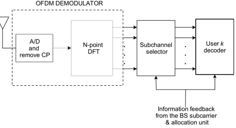
Subchannel selector . . . Information feedback from the BS subcarrier
& allocation unit N-point DFT A/D and remove CP OFDM DEMODULATOR . . . User k decoder
Figure 3.3: k-th user receiver for OFDMA downlink transmission with adaptive resource alloca-tion
it is also to maintain the rate proportionality among the users based on given proportional constraints rather than achieving a specific requested data rate.
The concept of dynamic resource allocation in an OFDMA downlink transmission is il-lustrated in Figure 3.2 and Figure 3.3. At the BS, the information about the users’ channel responses are sent to the multi-user subcarrier and power allocation unit, which maps the users’ data over the selected subcarriers choosing the best transmission mode (coding and/or mod-ulation scheme). The complex symbols at the output of the modulators are fed to an OFDM modulator and transmitted over the channel.
At the k-th user, the received signal is demodulated and the recovered frequency-domain samples are passed to subchannel selector, which takes into account the information about
channel allocation of user k. Then, the selected samples are decoded, thus providing the final detected bit by means of an appropriate detection strategy. The information about subcarrier and power allocation are sent by the BS to each user on a control channel. This exchange of information leads to a certain transmission overhead which tends to reduce the achievable data throughput. This problem can be mitigated by grouping sets of adjacent subcarriers into subchannels with similar fading characteristic. As a result, assuming that the bandwidth of a subchannel is smaller than the channel coherence bandwidth, the channel spectrum can be approximated as flat in the sub-channel. Resource allocation is thus performed on subchannels rather than on subcarriers causes almost no loss in diversity. These assumptions are coherent with that is being done in existing OFDMA systems. For example, in the WiMAX [2] band AMC zone contiguous subcarriers and OFDM symbols are grouped together into one basic allocation unit, called a sub-channel. Similarly, in the UTRAN LTE system [3] the subcarriers in each TTI are grouped into equal sized physical resource blocks; each block is allocated to a single user, and a user can be scheduled on multiple blocks. In the remainder, unless differently stated, we have neglected the impact of the control feedback channel on the system performance. We consider a downlink communication in an OFDMA system where the BS and K users are equipped with a single antenna. The overall frequency spectrum is divided into N orthogonal subcarriers. We also assume that the BS has perfect knowledge of CSI for each user, thus allowing the BS to dynamically allocate power and subcarriers according to channel quality. Using the Shannon capacity as a measure of data-rate achieved on a given subchannel, the data rate for user k is
Rk = N ∑ n=1 rk,n= B N ∑ n=1 ak,nlog2(1 + γk,n), (3.20)
where ak,n is a binary variable that assumes value 1 if subcarrier n is allocated to user k, and zero otherwise. γk,nis the SNR for user k on subcarrier n, defined as
γk,n=
PnHk,n σ2
w
, (3.21)
with Hk,n denoting the channel gain (accounting for pathloss and multipath fading) between user k and BS on the n-th link.
3.2 Multi-user OFDM systems
3.2.1
Multi-user RA algorithms
The RA resource allocation problem is formulated as follows:
max {ak,n},{Pn} K ∑ k=1 N ∑ n=1 rk,n (3.22) K ∑ k=1 ak,n≤ 1 n = 1, . . . , N (3.22.1) N ∑ n=1 Pn≤ Ptot, (3.22.2) ak,n∈ {0, 1} k = 1, . . . , K n = 1, . . . , N (3.22.3)
Constraints are described in (3.22.1)-(3.22.3): (3.22.1) implements orthogonal assignment, i.e., one subcarrier can be allocated to at most one user and, while in equation (3.22.2) Ptot is the maximum allowable transmit power.
Problem (3.22) is not convex since it needs to find the optimal set of subcarriers for each user, which turns out to be a combinatorial problem whose complexity increases exponentially with N . Indeed, finding optimal channel assignment requires KN searches, thus the overall optimization involvesO(NKN) operations. In detail, the k′-th user is given the n-th subcarrier on condition that
k′ = arg max
1≤k≤K{γk,n} . (3.23)
while the power allocated on subcarrier n is given by
Pn= ( µ− 1 gk′,n )+ (3.24)
with gk′,n, |Hk′,n|2/σ2wis the corresponding channel SNR for user k′ on subcarrier n and µ is a parameter that have to be set so as to satisfy the following condition
N ∑ n=1 ( µ− 1 gk′,n )+ = Ptot. (3.25)
The optimal solution to the non-convex optimization problem (3.22) can be achieved by means of Lagrangian dual function. It has been shown [35] that in multicarrier applications, even though the original resource allocation problems are non-convex, the duality gap becomes zero as the number of subchannels goes to infinity.
The Lagrangian of problem (3.22) is defined over domainD as L({Pn}, {rk,n}, λ) = K ∑ k=1 N ∑ n=1 rk,n− λ ( N ∑ n=1 Pn− Ptot ) , (3.26)
where D is defined as the set of all Pn > 0 for k = 1, . . . , K and n = 1, . . . , N . The Lagrange dual function is
g(λ) = max {Pn},{rk,n}∈D
L({Pn}, {rk,n}, λ). (3.27)
Equation (3.26) suggests that the maximization of L({Pn}, {rk,n}, λ) can be decomposed into N independent optimization problems,
gn′(λ) = max {Pn}∈D {K ∑ k=1 rk,n− λPn } n = 1, . . . , N (3.28)
Thus, the Lagrange dual function becomes
g(λ) = N ∑ n=1
g′n(λ) + λPtot, (3.29)
Let us assume that user k is allocated on subchannel n. Given a fixed value of λ, the object of max operation in (3.28) is a concave function of Pn. The optimality condition maximizing gn′(λ) is given by Pn= ( B log 2λ− gk,n )+ . (3.30)
By searching over all K possible user assignment for subcarrier n, it is possible to evaluate gn′(λ) and, eventually, the overall Lagrange dual function g(λ). Then, to find λ∗≥ 0 maximizing g(λ), an iterative approach based on the bisection method [25] requiringO(NK) iterations is utilized until the convergence is reached. It has been shown that the solution obtained in the dual domain becomes a global optimal solution as the number of subcarriers increases [36].
3.2 Multi-user OFDM systems
3.2.1.1 Multi-user RA with fairness
The problem of maximizing the total data rate while guaranteeing at the same time fairness among users may be formulated in several ways. Among these, Rhee and Cioffi [33] formulated the problem of assigning resources with the goal of maximizing the minimum capacity offered to each user. Mathematical formulation of this problem is
max min k Rk (3.31) K ∑ k=1 ak,n≤ 1 n = 1, . . . , N (3.31.1) N ∑ n=1 Pn≤ Ptot, (3.31.2) ak,n∈ {0, 1} k = 1, . . . , K n = 1, . . . , N (3.31.3)
The idea is to assign more power to users with poor channel conditions so as to guarantee a data rate which can be comparable to that of users with better channel gains. Since the problem (3.31) is not convex, its optimal solution can only be found through an exhaustive search over all possible channel assignment satisfying constraints (3.31.1)-(3.31.3), leading to high computational complexity. Rhee and Cioffi [33] proposed a reduced complexity subcarrier allocation algorithm, which is based on flat transmit power. Based on this assumption, the power allocated on each subcarrier is constant and equal to Pn = Ptot/N . Let Sk be the set of allocated subchannels to user k. The subcarrier allocation algorithm is summarized by the following pseudocode (Algorithm1):
Algorithm 1 Max-min subcarrier Allocation 1: A← {1, . . . , N} ◃ Initialization 2: for k← 1 to K do 3: Rk← 0, Sk← ∅ 4: end for 5: for k← 1 to K do
6: Find n satisfying|Hk,n| ≥ |Hk,j| for j ∈ A
7: Rk← B log2 ( 1 +Pn|Hk,n| 2 σ2 w ) 8: Sk← Sk∪ {n}; A = A − {n} 9: end for 10: while A̸= ∅ do
11: Find k satisfying Rk≤ Rifor all i, 0≤ i ≤ K
12: For the found k, find n satisfying|Hk,n| ≥ |Hk,j| for j ∈ A 13: Rk← Rk+ B log2 ( 1 +Pn|Hk,n| 2 σ2 w ) 14: Sk← Sk∪ {n} 15: A← A − {n} 16: end while
3.2 Multi-user OFDM systems
When users have different requirements on data rate, a fair solution is represented by intro-ducing proportional constraints among the users’ data rates [37]. Mathematical formulation of this problem is given by
max {ak,n},{Pn} K ∑ k=1 Rk (3.32) K ∑ k=1 ak,n≤ 1 (3.32.1) N ∑ n=1 Pn≤ Ptot, (3.32.2) R1: R2: . . . : RK = α1: α2: . . . : αK (3.32.3) ak,n∈ {0, 1} n = 1, . . . , N k = 1, . . . , K. (3.32.4)
In (3.32.3) α1: α2: . . . : αK is the set of predetermined proportional constraints where αk is a positive real number with αmin = 1 for the user with the least required proportional rate. In [37], the authors propose a suboptimal approach based on the following steps: i) assuming a uniform power distribution, subcarriers are assigned to each user by giving priority to the user with the least achieved proportional rate, i.e., Rk/αk. ii) In the second step, the power is reallocated between the users and then among the subcarriers through water-filling to guarantee the rate proportionality among the users.
Algorithm 2 Proportional fairness subcarrier allocation 1: A← {1, . . . , N} ◃ Initialization 2: for k← 1 to K do 3: Rk← 0, Sk← ∅ 4: end for 5: for k← 1 to K do
6: Find n satisfying|Hk,n| ≥ |Hk,j| for j ∈ A
7: Sk← Sk∪ {n} 8: A← A − {n} 9: Rk← B log2 ( 1 +Pn|Hk,n|σ2 2 w ) 10: end for 11: while A̸= ∅ do
12: Find k satisfying Rk/αk≤ Ri/αi for all i, 1≤ i ≤ K 13: Find n satisfying|Hk,n| ≥ |Hk,j| for all j ∈ A
14: Sk← Sk∪ {n} 15: A← A − {n} 16: Rk← B log2 ( 1 +Pn|Hk,n| 2 σ2 w ) 17: end while
The subcarrier allocation algorithm (Algorithm 2) tends to allocate to each user those subchannels with the highest SNRs. At each iteration, the user with the lowest proportional capacity has the possibility to pick the best subchannel. The allocation algorithm is suboptimal since it assumes equal power over all subcarriers. With the power allocation performed in the second step of the proposed algorithm, fairness is achieved among users. To find the k-th user’s power Pn, Lagrange multiplier techniques [25] are used to formulate and then solve the optimization problem resulting in K nonlinear equations with K unknowns. These equations are not linear and a closed form solution does not exist, thus non-linear iterative methods such as Newton-Raphson [38] and its variants may be used.
3.2.1.2 Numerical results
In this section we evaluate the performance of the RA resource allocation algorithms that we have described in the previous subsection. We consider a single-cell OFDMA system with radius of the cell equal to 500 m. The BS has a maximum transmit power Ptot= 1 W and the number of subcarriers is N = 192. The data sub-carriers spacing was set to 15 kHz, giving the total transmit bandwidth of 2.88 MHz, with the centre frequency of 2 GHz. We consider a population
3.2 Multi-user OFDM systems
of static users within the cell, while the channel modeled according to the TU scenario [39]. The results presented in this section are obtained for all algorithms presented in Section 3.2.1over 500 realizations. For the sum rate maximization with proportional rate constraints two different sets of rate constraints have been studied: the case where the rate constraints are set equal for all users (Prop rate 1), i.e. αk = 1 (k = 1, . . . , K), and the case where the rate constraints are set proportional to the user pathloss (Prop rate 2).
Figure 3.4 shows the average throughput for the different algorithms: the sum rate maxi-mization algorithm achieves the highest throughput and the max-min the lowest. The results show also the flexibility of the algorithm with proportional rate constraints. As expected, when the set of rate constraints are all equal its behavior is almost identical to the max-min algo-rithm. On the other hand, when the system tends to favor the users nearer to the BS, the throughput approaches the sum rate results.
Figure 3.5 shows the average fairness index (according to the definition in [40]) for the various RA algorithms. In this case the max-min and the algorithm with equal rate constraints outperform all the others. The algorithm with rate constraints proportional to the pathloss even if guarantees access to all users is not very fair. This is due to the fact that in our simulation setting the difference in patlhoss can be several orders of magnitude large. Thus, users close to cell boundaries will have a much smaller throughput than users near the BS.
4 6 8 10 12 14 16 0 0.2 0.4 0.6 0.8 1 Number of users Fairness Sum rate Max−min Prop rate 2 Prop rate 1
4 6 8 10 12 14 16 1.5e7 2.0e7 2.5e7 3e7 3.5e7 4e7 Number of users Throughput Sum rate Prop rate 2 Prop rate 1 Max−min
Figure 3.5: Throughput vs. number of users
3.2.2
Multi-user MA schemes
Margin-adaptive resource allocation algorithms are formulated with the goal of minimizing the overall transmitted power subject to individual user rate constraints. The mathematical formulation of this optimization problem is
min {ak,n},{Pn} N ∑ n=1 Pn (3.33) K ∑ k=1 ak,n≤ 1 (3.33.1) N ∑ n=1 rk,n≥ Rk,min k = 1, . . . , K (3.33.2) ak,n∈ {0, 1} k = 1, . . . , K n = 1, . . . , N (3.33.3)
Constraints are expressed by equations (3.33.1)-(3.33.3). In (3.33.2) Rk,minis the minimum data rate for user k. As for RA algorithms, looking for a solution of (3.33) results into a combinatorial optimization problem, which requires an exhaustive search over all possible channel assignments. Hence, the optimal solution can be achieved by using standard optimization techniques. The Lagrangian of (3.33) is given by L {{Pn}, {rk,n}, µ} = N ∑ n=1 Pn− K ∑ k=1 µk ( N ∑ n=1 rk,n− Rk,min ) . (3.34)
3.2 Multi-user OFDM systems
The Lagrange dual function is
g(µ) = min {Pn},{rk,n}∈D
L ({Pn}, {rk,n}, µ) . (3.35)
Rearranging the order of the sum terms, the minimization of (3.34) can be decomposed into N independent optimization problems as follows
g′n(µ) = min {Pn}∈D { K ∑ k=1 Pn− K ∑ k=1 µk N ∑ n=1 rk,n } (3.36)
Thus, the Lagrange dual function can be rewritten as
g(µ) = N ∑ n=1 gn′(µ) + K ∑ k=1 Rk,min, (3.37)
Once the vector µ is fixed, the object of the min operation is a convex function of Pn. The solution for minimization of g′n(µ) is given by
Pn = ( Bµk log 2 − 1 gk,n )+ . (3.38)
In order to find the optimal value µ∗ ≽ 0 that maximizes g(µ), the update of µ can be efficiently performed by employing the ellipsoid method [25], which is a generalization of the bisection method to problems in multi-dimensional spaces. At iteration p, this algorithm finds a new ellipsoid
E(p)={z∈ RK: (z− µ(p))TA(p)(z− µ(p))≤ 1} (3.39)
centered in µ(p) and with a shape defined by the positive semidefinite matrix A(p). By
con-struction, E(p) contains the optimal µ∗ and its volume is smaller than that of E(p−1), the ellipsoid found at the preceding iteration. Hence, after a certain number of iterations the ellip-soid’s volume will tend to zero and its center will coincide with µ∗. Ellipsoid method involves O(n2) iterations, with n denoting the number of variables [25] and utilizes as a subgradient the
following vectors: dk = Rk,min− N ∑ n=1 r∗k,n k = 1, . . . , K (3.40)
where r∗k,n and Pn∗ are the optimal solution for problem (3.35) for a fixed µ. The overall optimization needsO(K2) iterations of optimization problem with complexity ofO(NK). Thus,
O(NK3) executions are required to find the optimal solution of problem (3.33).
Another way to solve problem (3.33) is proposed by Wong et al. in [26]. Here the authors find a suboptimal solution which is based on the relaxation of the integrality condition on the
allocation variable ak,n. In this case, the latter can also be interpreted as the time-sharing factor for user k on subcarrier n. The allocation problem is reformulated as
min {ak,n},{Pk,n} K ∑ k=1 N ∑ n=1 ak,nPk,n (3.41) K ∑ k=1 ak,n≤ 1 n = 1, . . . , N (3.41.1) N ∑ n=1 ρk,n≥ Rk,min k = 1, . . . , K (3.41.2) ak,n∈ [0, 1] n = 1, . . . , N k = 1, . . . , K. (3.41.3) where Pk,nis the power transmitted by the BS to the user k on subcarrier n, whereas in equation (3.41.1) ρk,n= ak,nrk,nis a new rate variable and ak,n can take all values within the interval [0, 1]. With this new parameter, the optimization problem can be reformulated as a convex minimization problem over a convex set. Moreover, using Shannon formula, Pk,nis function of ρk,nand ak,nas Pk,n= (2 ρk,n ak,n − 1) 1 gk,n (3.42) Thus, the Lagrangian of problem (3.41) is
L({ρk,n}, {ak,n}, λ, µ) = K ∑ k=1 N ∑ n=1 ( 2 ρk,n ak,n − 1 ) ak,n gk,n − K ∑ k=1 λk ( N ∑ n=1 ρk,n− Rk,min ) − N ∑ n=1 µk (K ∑ k=1 ρk,n− 1 ) (3.43)
After differentiatingL({ρk,n}, {ak,n}, λ, µ) with respect to ρk,nand ak,n, we obtain the neces-sary conditions for the optimal solutions, ρ∗k,nand a∗k,n. Given a fixed set of Lagrange multipliers λk, k = 1, . . . , K, we have ρk,n ak,n = 0 λk ≤ log 2/gk,n log2(λkgk,n/ log 2) λk≤ log 2/gk,n
(3.44) and a∗k′,n= 1 k = arg min{τ (λk, gk,n)} 0 otherwise (3.45) where τ (λk, gk,n) = λkgk,n− log 2 log 2· gk,n − λ klog2 ( λkgk,n log 2 ) (3.46) In order to determine the set of λk so as to satisfy the users’ rate constraints, Wong et al. follow an iterative approach that is performed for each user in the system. This procedure repeats for