DOCTORAL SCHOOL of ENGINEERING
SECTION OF MECHANICAL AND INDUSTRIAL ENGINEERING
XXVI CYCLE
IGCC COMBINED CYCLE SECTION:
GAS TURBINE AND STEAM CYCLE MODELS AND SIMULATORS
PhD Student
Stefano Mazzoni
Tutor
Coordinator
Pag. 2 of 202
Index
Index ... 2 Index of Figures ... 7 Nomenclature ... 14 Introduction ... 20Chapter I: IGCC Power Plants ... 22
1.0 Introduction ... 22
1.1 Introduction on IGCC Power Plants... 22
1.1.1 Existing IGCC Plants ... 23
1.1.1.1 Wabash River IGCC Repowering Project ... 23
1.1.1.2 Tampa Electric Company IGCC Plant ... 24
1.1.1.3 Puertollano IGCC plant ... 25
1.1.1.4 Buggenum IGCC Plant... 26
1.1.1.5 Nakoso IGCC Plant ... 27
1.2 H2-IGCC Power Plant ... 29
1.2.1 Gasification Island ... 31
1.2.1.1 Coal Milling and Drying ... 32
1.2.1.2 Air Separation Unit (ASU) ... 33
1.2.1.3 Gasifier, Sygnas Cooler and Scrubber ... 33
1.2.1.4 Water Gas-Shift ... 34
1.2.1.5 Acid Gas Removal Unit (AGR) ... 35
1.2.1.5.1 H2S removal unit ... 36
1.2.1.5.2 CO2 removal unit and CCS ... 36
1.2.2 Power Island ... 37
1.2.2.1 Gas Turbine ... 38
1.2.2.2 Steam Cycle ... 38
1.3 Technical Background of H2-IGCC Power Island ... 39
1.3.1 Gas Turbine ... 39
1.3.1.1 Compressor ... 41
Pag. 3 of 202 1.3.1.3 Expander ... 43 1.3.1.4 Cooling System ... 44 1.3.2 Steam Cycle ... 45 1.3.2.1 HRSG ... 47 1.3.2.2 Steam Turbine ... 49 1.3.2.3 Condenser ... 50 1.4 Reference ... 51
Chapter II: Modelling Approach and Solution Strategy ... 53
2.0 Introduction ... 53
2.1 Thermo-mechanical Systems and modular approach ... 54
2.1.1 Modular Approach ... 55
2.2 Modelling Approach ... 56
2.3 Methodological Approach ... 59
2.4 Solution Strategy ... 60
2.4.1 Plant Unbalance Definition ... 61
2.4.2 Objective Function Definition ... 62
2.5 Solution Methods ... 63
2.5.1 Sequential ... 63
2.5.2 Simultaneous ... 63
2.5.3 Hybrid ... 66
2.6 Reference ... 69
Chapter III: IGCC Component Models ... 70
3.0 Introduction ... 70
3.1 Fluid Properties ... 70
3.1.1 Gas Properties ... 70
3.1.2 Steam properties ... 72
3.1.3 Working fluid properties ... 73
3.2 Gas Turbine Component Models ... 77
3.2.1 300MW F Class GT Brayton Cycle Evaluation Model ... 77
Pag. 4 of 202
3.2.1.2 Combustion Chamber Section ... 79
3.2.1.3 Expander Section ... 79
3.2.1.4 Gas Turbine Equations ... 80
3.2.1.5 GT Global Model for the evaluation of the overall cooling mass flow ... 82
3.2.2 Compressor ... 83
3.2.3 Combustion Chamber ... 84
3.2.4 Expander Model ... 87
3.2.5 GT Cooling Model ... 91
3.2.5.1 Heat transfer scheme and cooling scheme ... 91
3.2.5.1.1 Flow in the expander stages ... 93
3.2.5.2 Blade Cooling Model ... 100
3.2.5.2.1 Cooling Effectiveness ... 106
3.2.5.2.2 Effectiveness – Number of heat Transfer Unit ... 107
3.3 Steam Cycle Component Models ... 112
3.3.1 Heat Transfer Devices ... 113
3.3.2 Condenser ... 119
3.3.3 Steam Turbine ... 120
3.3.4 Deaerator ... 123
3.3.5 Pump ... 124
3.3.6 Pressure Loss Devices ... 127
3.3.7 Junctions ... 127
3.3.7.1 Water/Steam Mixer ... 128
3.3.7.1 Gas Mixer ... 128
3.3.8 Splitter ... 130
3.4 Gasification Island Simulator ... 131
3.4.1 Gasification Block ... 131
3.4.2 Water Gas Shift Block ... 134
3.4.3 Carbon Capture and Sequestriation Block ... 134
3.5 Reference ... 135
Pag. 5 of 202
4.0 Introduction ... 137
4.1 Gas Turbine Component Simulators ... 137
4.1.1 Reference GT Brayton Cycle Evaluation and overall coolant flows ... 137
4.1.2 Compressor ... 139
4.1.3 Combustion Chamber ... 144
4.1.4 Expander ... 146
4.2 Cooling System ... 155
4.3 Gas Turbine Simulator ... 156
4.3.1 CH4 Gas Turbine ... 157
4.3.1.1 Nominal Running Point ... 158
4.3.1.2 Part Load Analysis ... 159
4.3.1.3 Simulator Validation ... 160
4.3.2 Hydrogen Rich Syngas Gas Turbine ... 161
4.3.2.1 33H2R Base Load Map ... 164
4.3.3 Gas Turbine Control Rules ... 165
4.4 Steam Cycle Component Simulator ... 167
4.4.1 HRSG ... 167
4.4.2 Steam Turbine ... 171
4.4.3 Condenser ... 173
4.5 Steam Cycle Simulator ... 174
4.6 Power Island Simulator ... 176
4.7 Reference ... 181
Chapter V: IGCC Plant Simulator ... 182
5.0 Introduction ... 182
5.1 Gasification Island Simulator ... 183
5.2 Control policies for optimum, safe and stable operating conditions ... 185
5.2.2 Plant Control Philosophy ... 185
5.3 H2-IGCC Plant Simulator ... 188
5.4 H2-IGCC Plant Mapping ... 188
Pag. 6 of 202 5.4.2 Ambient condition changes ... 195 5.4.3 Discussion and Concluding Remarks ... 200 5.5 Reference ... 202
Pag. 7 of 202
Index of Figures
Fig. 1.1: Block scheme of an IGCC plant without CCS (from [1]) ... 22
Fig. 1.2: Block scheme of an IGCC plant with CCS (from [1]) ... 22
Fig. 1.3: Schematic view of the IGCC Wabash river power plant [2] ... 23
Fig. 1.4: Schematic view of the IGCC Tampa power plant [3] ... 24
Fig. 1.5: Schematic view of the Puertollano Tampa power plant [4] ... 25
Fig. 1.6: Schematic view of the Buggenum IGCC power plant [5] ... 26
Fig. 1.6b: Schematic view of the Nakoso IGCC power plant [6] ... 27
Table 1.1: Design features of coal fed IGCC power plants ... 28
Table 1.2: Performance of coal fed IGCC power plants ... 29
Fig. 1.7: H2-IGCC & CCS Reference Plant Layout [10] ... 30
Fig. 1.8: H2-IGCC plant block scheme ... 31
Table 1.3: Mass Composition and heating values of reference IGCC Coal [10] ... 32
Fig. 1. 9: Sketch of H2-IGCC coal input, milling and drying system ... 32
Fig. 1.10: Sketch of H2-IGCC ASU sub-system ... 33
Fig. 1.11: Sketch of H2-IGCC Gasification, Syngas Cooling and Scrubber Sub-System ... 34
Fig. 1.12: Sketch of H2-IGCC WGS Sub-System ... 35
Fig. 1.13: Sketch of H2-IGCC AGR Sub-System ... 36
Fig. 1.14: Sketch of the H2-IGCC Gas- Steam Combined Cycle Layout ... 37
Table 1.4: Generic 250-300MW Class Gas Turbines ... 40
Table 1.6: Siemens and Ansaldo GT - Characteristic Quantities ... 40
Fig. 1.15: Cross Section of the SGT5 – 4000F (94.3A) ... 40
Fig. 1.16: Schematic View of the Compressor Bleed Sections (courtesy of Siemens) ... 41
Fig. 1.17: SGT5 – 8000H – Siemens AG 2012. ... 42
Fig. 1.18: Main Flow path in the Combustor (Ansaldo) – As Example ... 42
Fig. 1.19: Cross Section of the Cooling Paths (SIEMENS) ... 43
Fig. 1.20: Temperature distribution between combustor outlet and 1st Nozzle vane inlet [16] 44 Fig. 1.21: Scheme of SGT6-5000F three pressure level with drum type evaporator combined cycle [23] ... 45
Fig. 1.22: Existing Plant Specification ... 46
Fig. 1.23: Specifications of under construction plant... 46
Pag. 8 of 202 Fig. 1.25: Typical 3 pressure level HRSG arrangement for combined plant (DRUM Type
EVA) ... 47
Fig. 1.26: Scheme of Conventional Drum VS Benson Once Through Boiler [23] ... 48
Fig. 1.27: Sketch of a finned tube bundle ... 48
Fig. 1.28: Cross Section of SST5-3000 Steam Turbine [26] ... 49
Fig. 1.29: SGT5-4000F and SST5-5000 electric generator connection [27] ... 49
Fig. 1.30: Water Cooling Condenser [24] ... 50
Fig. 2.1: Sketch of IGCC plant Diagram ... 53
Fig. 2.2: Sketch of the module input, output and attributes ... 55
Fig. 2.3: Finned Tube Heat Transfer Device - Stations and central node ... 56
Fig.2.4: Tube Bundle – Stations and central Node ... 57
Fig.2.5: Axial Compressor – Stations and central Node ... 57
Fig.2.6: Finite Volume Row – Stations and central Node ... 58
Fig.2.7: Condenser – Multi-zone heat transfer device ... 58
Fig. 2.8: Sketch of k-th Module ... 61
Fig. 2.9 : modular structure calculation method – ECRQP ... 64
Fig. 2.10: Solution Path along the Locus of P(z,r) Minima ... 65
Fig. 2.11: Hybrid methodology – Genetic Algorithm/ECRQP ... 67
Fig. 2.12: complex modular structure calculation method – Hybrid Algoritm GA-ECRQP ... 68
Fig. 3.1: Block Scheme of the ENGA 5 Subroutine ... 71
Fig. 3.2: Block Scheme of the COGAS 5 Subroutine ... 71
Fig. 3.3: Block Scheme of the SYGPROP Subroutine ... 72
Table 3.0a: Wet Air – RH60% mass fraction composition ... 73
Table 3.0b: Gas Mass Fraction Composition of CH4 combustion with an 45 AFR ... 73
Table 3.0c: ISO Air Properties ... 74
Table 3.0d:Gas Properties of CH4 combustion with an 45 AFR ... 75
Table 3.0e: Steam Properties for different pressure ... 76
Blue – Water ; Red - Steam ... 76
Fig. 3.4-a: Scheme of a Generic 300MW F Class GT ... 77
Fig.3.4-b: Scheme of a GT Brayton Cycle ... 77
Fig. 3.5: Turbine Inlet Temperature Nomenclature ... 82
Fig. 3.6: Sketch of compressor through Flow Section ... 83
Fig. 3.7: Compressor sub-components to account the bleed extraction ... 84
Pag. 9 of 202
Fig. 3.9: Combustion Chamber Off-Design Curves ... 86
Fig. 3.10: Sketch of the Expander through Flow Section ... 87
Fig. 3.11: Schematic representation of a expander cooled row ... 88
Fig. 3.12 Schematic Representation of the Mixing: ... 89
a) Momentum Conservation – b) Thermal Equilibrium ... 89
Fig. 3.13: Cooling and main flow expansion on h-s chart ... 90
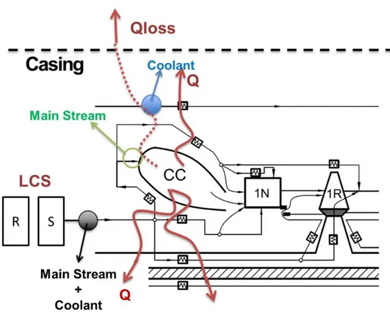
Fig. 3.14: Cross Section of the Cooling Paths (SIEMENS) ... 92
Fig. 3.15: Schematic View of the main stream and coolant streams along the combustor ... 92
and of the heat fluxes moving through the GT to the casing and to the inner components (shaft, disk, etc.) ... 92
Fig. 3.16: Schematic view of the cooling paths along the disks – As example ... 94
Fig. 3.17: Example of a Generic Gas Turbine Cooling Path along Stator and Rotor Row ... 95
Fig. 3.18: Schematic View of the Cooled components of the Stator Row – As Example ... 95
Fig. 3.19: Typical Temperature Distribution along a 1st Stage Aeronautic Rotor Disk – As Example ... 96
Fig. 3.20: Schematic View of a 1st Nozzle Vane Cooling Components – As Example ... 97
Fig. 3.21: Schematic View of a 1st Rotor Blade Cooling Components – As Example ... 97
Fig. 3.22: Comparison between cooled blade and uncooled blade coolant flow ... 98
Table 3.1: Fractions of the overall mass flow for each row (in percentage %) ... 98
Fig. 3.23: Schematic View of the cooling path ... 99
from the compressor bleeding station to the expander row injection station ... 99
Fig. 3.24: Sketch of a Rotor Blade temperature distribution along the layers ... 100
Fig. 3.25: Simplified view of the thermal resistance for a generic blade ... 101
Fig 3.26: Schematic view of the enhance system of the internal heat transfer coefficient .... 102
Fig. 3.27 a-b: a) rib distribution – b) Influence of Turbulent promoter on the NU number .. 103
Fig 3.28 : Influence of jet impingement architecture on internal heat transfer coefficient .... 103
Fig 3.29: Schematic view of the depression of the external heat transfer coefficient ... 104
owing to the film cooling ... 104
Fig. 3.30: Typical heat transfer distribution among the blade row surface ... 105
Fig. 3.31: External heat transfer coefficient depressed by the film cooling ... 105
Fig. 3.32: Influence of the Thickness TBC layer on the coolant flows ... 106
Fig. 3.33: Temperature profile along the various blade layers ... 107
Fig. 3.34: schematically main stream temperature decrease – Not to scale ... 109
Pag. 10 of 202
Fig. 3.36: Sketch of H2-IGCC Steam Cycle ... 112
Fig. 3.37: Heat Transfer Device scheme ... 113
Fig. 3.38: Sketch illustrating nomenclature for in-line tube arrangements [15] ... 115
Fig. 3.39: NU vs Re max for in-line tube arrangement [15] ... 116
Fig.3.40: Correction Factor to account the number of the Row [15] ... 116
Fig.3.41: Heat Flux VS Temperature Difference ... 117
Table 3.1: coefficient exponents of the heat transfer coefficient calculation ... 119
Fig. 3.42: Multi-Zone Condenser ... 119
Fig. 3.43: Scheme of a generic steam expander ... 120
Fig. 3.44: Stodola Ellipse Sketch and steam turbine body with governing valve ... 121
Fig. 3.45: Deaerator scheme ... 123
Fig. 3.46: scheme of a generic pump ... 124
Fig. 3.47: Pumps Characteristic Non-Dimensional Curves ... 126
Fig 3.48: Mixer scheme ... 128
Fig 3.49: Gas Mixer scheme ... 129
Fig. 3.50: Splitter Scheme ... 130
Fig. .3.51: Gasification Island Block Scheme ... 131
Fig. 3.52: Gasifier Reactor Model Scheme ... 132
Fig. 3.53: Syngas Cooler Model Scheme ... 133
Fig. 3.54: WGS Block Scheme ... 134
Table 4.0a: Input Data for Cycle Calculation ... 138
Table 4.0b: Cycle Mass Flows and Outlet Quantites ... 138
Table 4.0c: Evaluation of the overall coolant mass flow ... 139
for various coolant and blade temperature, respectively ... 139
Table 4.1: Compressor Sizing Quantities ... 140
4.1: H2-IGCC Compressor Through Flow Shape ... 140
Fig. 4.3: Pressure ratio versus corrected mass flow curves at different ... 142
compressor inlet temperatures ... 142
Fig. 4.4: Compressor isentropic efficiency versus pressure ... 142
ratio curves at different compressor inlet temperatures ... 142
Fig. 4.5: Pressure ratio versus corrected mass flow curves at different VIGV openings ... 143
Fig. 4.6: Compressor isentropic efficiency versus pressure ... 143
ratio curves at different IGV openings ... 143
Pag. 11 of 202
Table 4.3: Combustion Chamber output quantities ... 145
Fig. 4.7: Combustion Chamber Off-Design Curves data ... 145
Table 4.4: Blade Cooling input ... 146
Table 4.5: Expander Sizing Input Data ... 147
Table 4.6: Expander output quantities ... 147
Table 4.7: Row by Row geometric quantities ... 147
Fig. 4.8: Expander through Flow Section including the rear frame ... 148
Fig. 4.9: 1st Rotor Velocity Diagrams ... 149
Fig. 4.10: 2nd Rotor Velocity Diagrams ... 150
Fig. 4.11: 3rd Rotor Velocity Diagrams ... 151
Fig. 4.12: 4th Rotor Velocity Diagrams ... 152
Fig. 4.13: Expander blade to blade overview ... 153
Fig. 4.14: Pressure Ratio vs Corrected mass flow... 154
for different firing temperature ... 154
Fig. 4.15: Total to Static Efficiency vs Pressure Ratio ... 154
for different firing temperature ... 154
Fig. 4.15b: Off-Design cooling effectiveness VS TCR ... 155
Fig. 4.16: ECRQP block scheme of the gas turbine matching ... 156
Fig. 4.17: Sketch of the Generic 300MW F Class GT Simulator ... 157
Fig. 4.18: Gas Turbine Through flow shape ... 157
Table 4.9: RO3 Simulator - Nominal Running Point CH4 Fed ... 158
Table 4.10: Results of the Lumped Model for cooling requirement - CH4 ... 159
Fig. 4.19: CH4 fed GT part load behaviour ... 159
Fig. 4.20: RO3 Power Output and Efficiency at Generator Terminals ... 160
Fig. 4.21: Siemens SGT5-4000F Power Output and Efficiency at Generator Terminals [3] 160 Fig. 4.22: CH4 Gas Turbine Simulator Running Point for different fuel feeding ... 161
Table 4.11: GT Simulator and Cooling System Performance Results for the various Re-Staggering Steps ... 163
Fig. 4.23: 33H2R GT –Load and efficiency non dimensional value versus ambient temperature ... 164
Fig. 4.24: 33H2R GT –Tex and VIGV non dimensional data versus ambient temperature .. 164
Fig. 4.: 33H2R Gas Turbine Behaviour versus Ambient Temperature ... 165
Fig.4.: 33H2R Gas Turbine Behaviour versus Ambient Temperature ... 166
Pag. 12 of 202
Fig. 4.25: Gas Steam Combined Cycle plant layout ... 168
Table 4.13: Temperature Differences of HRSG ... 169
Fig. 4.26: Gas Side and Steam Side Temperature Profile along the HRSG stations. ... 169
Table 4.15: HRSG Sizing Results ... 170
Fig. 4.27: Sketch of the three turbine bodies and the HRSG interactions... 171
Table 4.16: Steam Turbine Sizing Quantities ... 172
Fig. 4.28: Steam turbine bodies (HP, IP, LP) ... 172
Off-Design behaviour for various steam mass flowand fixed condensing pressure. ... 172
Table 4.17: Condenser relevant sizing quantities ... 173
Fig. 4.29: Condenser Off-Design behaviour for different steam flows ... 173
Condensing pressure and cooling water temperature VS steam mass flow ... 173
Fig. 4.30: ECRQP block scheme of the steam cycle matching ... 174
Table 4.18: Steam Cycle Simulator – Nominal Running Point ... 175
Fig. 4.31: Schematic view of the H2-IGCC Power Island ... 176
Table 4.19: Power Island Nominal Running Point – ISO Conditions ... 177
Fig. 4.32: Non dimensional values of GT relevant quantities ... 178
for ISO conditions and changing GT load ... 178
Fig. 4.33: Non dimensional values of the steam side relevant quantities for various ISO conditions loads ... 180
Fig. 5.1a: Sketch of IGCC Plant ... 182
Power, Heat and mass flow interactions between the various plant sections ... 182
Fig. 5.1b: IGCC Layout Block Scheme ... 183
Fig. 5.2a: pressures trends and valve opening versus plant load ... 187
Fig. 5.2b: Sketch of the control system of the GT fuel admission valve ... 187
Table 5.1: Whole System Map – Test Case ... 188
Fig. 5.3: ISO Conditions – GT Exhaust Mass Flow and Temperature VS GT Load ... 189
Fig. 5.4: ISO Conditions – GT Nozzle Vane and Rotor Blade life consumption rates VS GT Load ... 190
Fig. 5.5: ISO Conditions –Superheating temperature (HP, IP, LP) VS GT Load ... 190
Fig. 5.6: ISO Conditions – Boiler Outlet Steam Mass Flow (HP, IP, LP) VS GT Load ... 191
Fig. 5.7: ISO Conditions – Whole System power VS GT Load ... 192
Fig. 5.8: ISO Conditions – Power Ratio VS GT Load ... 193
Fig. 5.9: ISO Conditions –33H2R Syngas and primary coal mass flow VS GT Load ... 193
Pag. 13 of 202
Fig. 5.10: ISO Conditions –IGCC Power and Efficiency VS GT Load ... 194
Fig. 5.11: GT Exhaust Mass Flow and Temperature VS Ambient Temperature ... 195
Fig. 5.12: ISO Conditions –Superheating temperature (HP, IP, LP) VS Ambient Temperature ... 196
Fig. 5.13: ISO Conditions – Boiler Outlet Steam Mass Flow (HP, IP, LP) VS GT Load ... 196
Fig. 5.14: ISO Conditions – Whole System power VS Ambient Temperature ... 197
Fig. 5.15: ISO Conditions – Boiler Outlet Steam Mass Flow (HP, IP, LP) VS GT Load ... 198
Fig. 5.16: ISO Conditions –33H2R Syngas and primary coal mass flow VS GT Load ... 198
Pag. 14 of 202
Nomenclature
33H2R-GT 33MJ/kg H2 Rich Fuel fed Re-Staggered Gas Turbine
af Vector of Actuality Function
AF Actuality Function
AFR Air Fuel Ratio
ANN Artificial Neural Network
ASU Air Separation Unit
b Vector of Boundary Conditions
BAT Best Available Technologies
BM Bulk Material
C Mass flow times heat capacity
CC Combustion Chamber, Combined Cycle
CCS Carbon Capture and Storage
CEM cooled expander model
CFD Computational Fluid Dynamics
CHP Combined Heat and Power
CHV Coal Heating Value
COND Condenser
cp specific constant pressure heat
cv specific constant volume heat
D Vector of Plant Model Inequalities
d Vector of Boundary Conditions, data
DB Data Base
DEGA Deaerator /Degasser
EBC Equivalent Brayton Cycle
ECLM Expander Cooling Lumped Model
ECO Economizer
ECRQP Equality Constraint Recursive Quadratic Programming
Eff Effectiveness
EVA Evaporator / Boiler
EX Extraction
f Life Consumption Rates (lcr)
Pag. 15 of 202
FOB Objective Function
fob Partial objective functions
FV Finite Volume
g Vector of Plant Geometric Data
GA Genetic Algorithms
GGT Generic Gas Turbine
GI Gasification Island
GT gas turbine
GTNM Gas Turbine Neural Model
GTS Gas Turbine Simulator
h enthalpy
H2R Hydrogen Rich
H2RS Hydrogen Rich Syngas HDGT Heavy Duty Gas Turbine
HFGTS high-fidelity gas turbine simulator HGTCR Hot Gas Thermal Capacity Rate
HP High Pressure
HRSG Heat Recovery Steam Generator
HTD Heat Transfer Device
IGCC Integrated Gasification Combined Cycle
IP Intermediate Pressure
J j-th Station
k heat ratio
k Coefficient
L Lagrangian Function, Load
LASM Lowest Allowable Stall Margin
LCS last compressor stage
LFV lumped finite volume
LHV Low Heating Value
LP Low Pressure
m mass flow
mb Bleeding Mass Flow
Pag. 16 of 202
mc Coolant Mass Flow
mg Gas Mass Flow
n Rotational Speed
N&C New and Clean
NC Nominal Condition
NG Natural Gas
NN Neural Network
NTU Number of Transfer Units
NV Nozzle Vane
OEM Original Equipment Manufacturer
P Power, Penalty Function
p Pressure, price
PI Power Island
PR Pressure Ratio
PRE Pre – Heater (Primary Economizer)
Q heat
QTH Thermal Power
R gas constant
R Rotor Blade
rf Vector of Reality Function
RF Reality Function
RGT Reference Gas Turbine
RH Relative Humidity
RHDGT Reference Heavy Duty Gas Turbine RMSE Root Mean Square Error
RO3 Roma Tre University
s Thickness
S surface
S Heat exchanger Surface
SC Steam Cycle
SH Super Heater
SoA State of the Art
Pag. 17 of 202
ST Steam Turbine
T temperature
Tb Blade Temperature
TBC Thermal Barrier Coating
Tc Coolant temperature
Tc Coolant Temperature
Tc Coolant Temperature
TCR, χ Thermal Capacity Ratio
Tf Firing Temperature
Tg Hot gas temperature
Tg Gas Temperature
TIT Turbine Inlet Temperature
TW Blade Temperature
U Global Heat transfer coefficient
Uc Coolant Heat Transfer Coefficient
UEBC Uncooled Equivalent Brayton Cycle
Ug Gas Heat Transfer Coefficient
UJ Heat Transfer Coefficient of j-th flow
VIGV Variable Inlet Guide Vane
W Work
WGS Water Gas Shift
x Vector of Unknown Variables
xx mass fraction composition
Y Generic Reference Variable
z Vector of unknown variables
Greek Symbol
Air fuel ratio β Pressure ratio
∆ Unbalance
ɛ Effectiveness
λ Thermal Conductivity, Lagrangian Multpliers
μ Dynamic Viscosity
Pag. 18 of 202
Vector of Degree of Freedom
ηc Cooling Effectiveness
ν Array of the Active Constraint
η Efficiency
p pressure loss
efficiency
Subscript
0 Reference Condition / Standard Condition
- negative # number * Reference + positive +/- sub-set 1,2…. Station Order amb ambient b Blade bJ j-th bleed
C Cold Stream, Compressor, Coolant
E Expander el electric ex Exhaust f fuel g Gas GT Gas Turbine H Hot Stream i Inlet is Isentropic min minimum N Nominal o Outlet p politropic r rotor blade
Pag. 19 of 202 RJ j-th rotor
s steam / stator vane s,i isentropic
SJ j-th stator
w water
Operators
Included into a set
Union of Set
Pag. 20 of 202
Introduction
Greenhouse gas carbon dioxide emitted during fossil fuel combustion leads to global climate warming, it influences human’s life more and more. Nowadays, people call for environmental friendly and higher efficient electric power production technologies, like integrated gasification combined cycle (IGCC) which was developed since 1970s. Due to the rising price of natural gas, depletion of petroleum and availability of coal, people pay more attention to coal energy. Accordingly, Europe, USA, China focus their interest on IGCC power plants equipped with Carbon Capture & Storage (CCS) technologies to meet the energy and environment requirements. An IGCC power plant is a combination of a chemical plant (coal gasification) that converts coal into a Synthetic Gaseous Fuel (SGF) and a gas-steam combined power plant that converts the chemical energy of SGF into electricity.
Roma Tre University has been partner of the H2-IGCC Project Under the EU's 7th Framework Programme for R&D . I’ve been involved in the H2-IGCC project as a PhD Student in the Professor Cerri research group. Roma Tre University has been interested in two sub-projects: Turbomachinery and System Analysis. Accordingly, I’ve been dealt with gas turbine, steam cycle and whole system topics.
Aim of this work is the development of an IGCC Power Plant Simulator that adopts a Lumped Performance (LP) methodology employing a Finite Volume (FV) approach based on detailed Architecture, Geometry, Lumped Physics and Chemistry including all the empirically known phenomena characterizing the specific behaviour of the plant components (i.e. GT, ST, Heat transfer devices, etc.). Such a simulator has been built up taking the available technologies and the state of the art of the existing F, G and H Class Gas Turbines and Steam Cycle specifications of many Manufacturers into account. Features of such a simulator have been developed as to be close to those of the existing machines of some European O&M’s.
Adoption of reality and actuality functions allows the simulator to be tailored ad hoc to the H2-IGCC plant layout and to be a replica of the reference plant. The simulator can be seen as a test bench of infinite sensors able to replicate and reproduce the whole system behaviour and to forecast the power production owing to the operating conditions change (i.e. prices, taxes, temperatures, etc.). To allow the simulator to give a real time response, neural network modules of some plant components have been carried out.
Modular approach of elementary component models (i.e. compressor, heat transfer device, pump, steam turbine, etc.) have been employed to perform the whole system simulator. Sizing and off-design analyses of each modelled IGCC power plant component have been performed
Pag. 21 of 202 and H2-IGCC plant simulator has been achieved by matching the various component maps together. Accordingly, plant part load behaviour have been investigated by means of such a simulator tool under the adoption of proper plant control policies that takes various aspects such as thermal and mechanical stresses as well as costs and life consumption rates of components into consideration.
As a result of such analyses, IGCC maps have been obtained for different ambient conditions and power demands.
Pag. 22 of 202
Chapter I
IGCC Power Plants
1.0 IntroductionIntegrated Gasification Combined Cycle (IGCC) power plants are one of the most innovative clean coal technology that puts together modern coal gasification systems, GTs and steam cycle for electric power production. In this chapter, State of the Art (SoA) and Technical Background (TB) of IGCC power plants and of the main components (i.e. gas turbine, heat recovery steam generator, steam turbine, etc.) constituting such plants are reported, respectively.
1.1 Introduction on IGCC Power Plants
IGCC plants are based on gasification that is one of the most flexible and clean process to generate synthetic fuels from solid and liquid heavy fuels. Emissions into the environment are lower in comparison with traditional coal plants, moreover gasification has the possibility to capture CO2 relatively efficiently. Two alternatives are given in Fig.1.1 and Fig. 1.2 where block schemes of an IGCC without Carbon Capture and Storage (CCS) and with CCS are depicted.
Fig. 1.1: Block scheme of an IGCC plant without CCS (from [1])
Pag. 23 of 202 Coal is converted into a Synthetic Gaseous Fuel (SGF) by a partial combustion (oxidation) gasification process. The raw gas contaminant substances such as sulfur and nitrogen compounds, mercury, coal ash, particulate matter, etc. and CO2 for CCS as well as for other uses, may be removed from the Raw Syngas (RS) by established techniques. The Clean Raw Syngas (CRS) is a clean, transportable gaseous energy carrier. Such a CRS is used to feed the Gas Turbine (GT) being the GT cycle the top one of the whole combined section. The Bottom Cycle is the steam one. Heat contained in the GT exhaust stream is recovered to produce steam in a Heat Recovery Steam Generator (HRSG). Additional steam is generated by the gasification and purification processes. Bottoming steam turbine is fed by the above steam to produce power.
1.1.1 Existing IGCC Plants
This section gives an outline of the existing coal based IGCC plants equipped with entrained flow gasifiers with a brief description of their main features.
1.1.1.1 Wabash River IGCC Repowering Project
Fig. 1.3: Schematic view of the IGCC Wabash river power plant [2]
In the Wabash River power plant (Fig. 1.3) the produced syngas is fed to a GE 7FA Gas Turbine. The gasification island is constituted by a low pressure ASU (6 bar), a slurry fed,
Pag. 24 of 202 oxygen blown two stage E-Gas gasifier, a firetube syngas cooler, and finally, by gas and water cleaning systems. Slag is removed from the slag bath at the base of the gasifier by a proprietary continuous letdown system.
The gas cleaning system is composed by a candle filter for hot gas filtration, a COS hydrolysis unit, a heat fransfer device to cool the gas, an acid gas removal section based on MDEA and a syngas saturation unit. To avoid COS catalyst degradation, a water scrubbing unit was added downstream the candle filter to remove chlorides. The H2S loaded gas exiting from MDEA regenerator stripper is sent to a Claus unit where elemental sulfur is produced. The tail gas is recycled to the gasifier. The power island is equipped with a GE 7FA GT and a HRSG that generates steam for a pre-existing 105 MW steam turbine. The NOx control is achieved by clean syngas saturation and by injection of intermediate pressure steam into the GT combustion chamber.
1.1.1.2 Tampa Electric Company IGCC Plant
Fig. 1.4: Schematic view of the IGCC Tampa power plant [3]
The Tampa Electric IGCC plant (Fig. 1.4) is constituted by a high pressure ASU, an oxygen blown, down flow, single stage Texaco gasifier including heat transfer devices for syngas cooling (a wall radiant cooler located below the gasifier, two parallel firetube convection
Pag. 25 of 202 coolers, two gas/gas heat exchangers), gas and water clean up sections. The power island is made of a GE 7FA GT based combined cycle.
The gas clean up comprises a particulate scrubber, a raw syngas gas cooling device, a COS hydrolysis unit to remove sulfur species (mainly H2S) and a MDEA based AGR system. The peculiarity of Tampa IGCC in respect to other IGCC existing plant consists in the production of sulfuric acid rather than elemental sulfur.
Nitrogen from the ASU is used for NOx formation control. In order to further reduce NOx emissions an additional syngas saturator was included in 2002. The project demonstration phase started in late 1996, and since then the plant has been successfully operated at design load. Occasional part load operations have been carried out with any particular problem.
1.1.1.3 Puertollano IGCC plant
Fig. 1.5: Schematic view of the Puertollano Tampa power plant [4]
The Puertollano IGCC plant (fig. 1.5) adopts the Prenflo pressurized entrained flow, oxygen blown gasification technology. The produced raw syngas is cleaned and supplied to a Siemens
Pag. 26 of 202 94.3 based gas-steam combined cycle. The oxygen is produced in an integrated ASU, which also produces nitrogen for feedstock drying and transport.
The raw syngas undergoes a complete cleaning process to eliminate the pollutants. Then it is saturated and sent to the GT combustion chamber. The GT is able of operating with both syngas and natural gas. Steam is generated in a HRSG fed by the GT exhaust, in heat transfer devices imbedded in the gasifier, and in heat exchangers for raw syngas cooling. The plant's target energy efficiency is 45% in ISO conditions. The heat recovery system arrangement for steam production is really effective. Other then power production, steam is used to accomplish several duties concerning coal preparation, gasification, desulphurization processes.
1.1.1.4 Buggenum IGCC Plant
Fig. 1.6: Schematic view of the Buggenum IGCC power plant [5]
The NUON (formerly Demkolec) plant at Buggenum (fig. 1.6) has been the first IGCC European demonstration project (1994). The plant is arranged with a high pressure ASU, a dry fed, oxygen blown Shell entrained flow gasifier, a first raw syngas cooling step to about 800°C (operated by recycling the fuel gas taken downstream the de-pulverisation section) followed by a water tube syngas cooler for saturated steam production. Gas cleaning apparatuses consist in a fly ash cyclone followed by a ceramic candles filter operating at 250°C, a water scrubbing unit, a COS hydrolysis unit, a Sulfinol based AGR section for H2S
Pag. 27 of 202 removal. The plant scheme is shown in Fig. 6.1. The power island is based on a Siemens V94.2 GT combined cycle with a turbine inlet temperature of 1100°C. Both saturation and nitrogen dilution of the syngas are adopted for NOx emission control. According to the design features of the Siemens GT and to the desire to achieve a high plant efficiency, the full integration between ASU and GT has been adopted.
1.1.1.5 Nakoso IGCC Plant
Fig. 1.6b: Schematic view of the Nakoso IGCC power plant [6]
The Nakoso IGCC demonstration project is owned by Japan’s Clean Coal Power R&D Co Ltd, a consortium of Japanese power utilities and research organizations. It is based on a two-stage, air blown MHI gasifier followed by cold syngas cleaning. The power island is arranged with a modified M701DA GT allowing an air extraction at compressor discharge to feed the air blown gasifier. A stand-alone ASU is included to produce nitrogen used as inert pressurized gas to feed the coal to the gasifier. The oxygen exiting the ASU is fed to the gasifier to enrich the gasification air [8]. The plant started demonstration operations during
Pag. 28 of 202 2007, after an extensive research and pilot testing program mainly carried out by CRIEPI (Japan’s Central Research Institute for the Electric Power Industry). A 42.4% net efficiency (LHV) based on Chinese bituminous coal has been achieved. The future use of US and Indonesian sub-bituminous coals is foreseen [7].
Main features and open literature available data regarding the existing coal fed IGCC plant are gathered in Table 1.1 and Table 1.2.
Table 1.1: Design features of coal fed IGCC power plants
Wabash River
Tampa El.
Company Puertollano Buggenum Nakoso Gasifier.
- Gasifier tech. GE Gas Texaco Prenflo Shell MHI
- gasifier Type
Two stage, O2, upflow, entrained
Single stage, O2, downflow,
entrained
Single stage, O2, upflow, entrained
Single stage, O2, upflow, entrained
Two stage, enriched air, upflow, entrained -feed system Slurry Slurry Dry coal Dry coal Dry coal
-recycle gas quench To second
stage no Large recycle Large recycle no
-Syngas Cooling Downflow firetube
Downflow radiant and convective
Two pass radiant and convective Downflow, watertube Downflow, watertube ASU
-pressure Low pressure High pressure High pressure High pressure
-air supply compr. Dedicated Dedicated 100% from GT 100% from GT Dedicated - nitrogen use Vented GT NOx control GT NOx Control GT NOx Control Coal transport
Gas Clen-up
- part. removal Candle filter Water scrubbing Candle filter Candle filter Ceramic filter
- COS hydrolysis Yes Yes Yes Yes Yes
- AGR solvent MDEA MDEA MDEA Sulfinol MDEA
- sulfur recovery Claus plant Sulfuric acid Claus plant Claus plant Gypsium
- Gas saturation Yes Yes Yes Yes No
Gas Turbine
-Type GE7 FA GE7 FA Siemens 94.3 Siemens 94.2 M701DA -Combustor Can annular Can annular Horizontal silos Vertical silos Can annular
- Firing temp. 1260 °C 1260 °C 1260°C 1100°C 1200°C
- NOx control Saturation and steam inj. Saturation and N2 dilution Saturation and N2 dilution Saturation and N2 dilution SCR
Pag. 29 of 202
Table 1.2: Performance of coal fed IGCC power plants
1.2 H2-IGCC Power Plant
In the scenario of the clean coal energy, the H2-IGCC Project under the EU’s 7th Framework Programme for R&D [9] is aimed to provide and demonstrate technical solution and related to the use of state-of-the-art Gas Turbines suitable to be fed with undiluted H2-rich syngas obtained from a pre-combustion CO2 capture process. Accordingly, a reference plant has been studied, according with project partners [10, 11]. Layout of such a H2-IGCC power plant is given in figure 7.1.
The plant combines a very complex fuel processing unit and a power production section based on a gas steam combined cycle. A macro-blocks view of the plant is given in Figure 8. The IGCC power plant with carbon sequestration and capture is a combination of a chemical plant (the gasification island) that converts coal into a Synthetic Gaseous Fuel (SGF) and a gas-steam combined power plant that converts the chemical energy of SGF into electricity.
The Gas turbine (GT) is a generic 300 MW one developed within the H2-IGCC project including all the features related to the updated best available technology. Shell gasification technology, low pressure ASU with no integration with the GT, two-stage sour gas shift and combined H2S and CO2 removal by a Selexol process have been adopted. Combined-cycle steam section is based on a three-pressure level HRSG cycle highly integrated with the gasification island. The plant produces a net power o some 400MW with an efficiency of 36.2%.
In this paragraph, description of the macro islands, gasification and power island, constituting the H2-IGCC power plant is given.
Wabash River Tampa El.
Company Puertollano Buggenum Nakoso
GT - P [MW] 192 192 196 155 130 ST - P [MW] 98 125 144 128 n.a Auxiliary P [MW] 36 66 37 31 n.a Net P [MW] 252 250 291 252 250 LHV Net η [%] 41.2 39.8 42.4 43 42.5 HHV Net η [%] 39.7 37.5 41.7 41.4 40.5
Pag. 30 of 202
Pag. 31 of 202
Fig. 1.8: H2-IGCC plant block scheme
1.2.1 Gasification Island
The Gasification Island (GI) is made of various macro sub-components such as Coal Milling and Drying (CMD), Air Separation Unit (ASU), Gasifier, Syngas Cooler, Scrubber, Water Gas Shift (WGS), Acid Gas Removal (AGR) and others. Such components are integrated by means of mass, power, heat interactions with the Power Island (PI).
Pag. 32 of 202
1.2.1.1 Coal Milling and Drying
The coal used in the reference IGCC plant is a mixture of various trade coals available on the world market characterized by a certain composition. Such a mixture mass composition is shown in Table 1.3.
Table 1.3: Mass Composition and heating values of reference IGCC Coal [10]
The coal is milled and dried. The milling process leads to a fine particulate coal powder ready for the gasification. The dried process leads to a moisture level of 2% wt. by burning approximately 0.9% of the shifted syngas. The transport and the injection of the coal is made by the pressurized N2 from the ASU. The amount of coal input depends on the power of GT. The sketch of the coal input subsystem is shown in Fig. 1.9.
Pag. 33 of 202
1.2.1.2 Air Separation Unit (ASU)
Ambient air fed into a three-stage intercooled compressor is discharged at the pressure of 5.5 bara. Then the compressed air is separated to oxygen with a purity of 95 mol% (with 2% N2, and 3% Ar) and pure N2 by ASU. At the end, the gaseous O2 is compressed to 55 bara in a nine stage intercooled compressor and fed to gasifier, while gaseous N2 is compressed to 80 bara in a multi-stage intercooled compressor and used for coal input system and fuel feeding to gasifier. Some excess N2 is exhausted from ASU. The ASU subsystem with air, O2 and N2 compressors is shown in Figure 1.10.
Fig. 1.10: Sketch of H2-IGCC ASU sub-system
1.2.1.3 Gasifier, Sygnas Cooler and Scrubber
Fine powder coal is pneumatically transported from CMD system into the gasifier by means of compressed 80 bara pure N2. Such a N2 is taken from the ASU subsystem together with the O2. A compressed O2 stream from the ASU is fed into the gasifier to react with the coal. Coal gasification takes place in the Shell gasifier at 45 bara and 1600°C. The single pass gasifier converts 99.3% carbon into raw syngas that contains CO, CO2, H2, COS. The melted ash leaves the bottom of the gasifier while the flying ash are captured by the ceramic filters. The rest of fine particular ash stayed in the raw syngas will be got rid of by after the cleaning processes. The tube membrane wall of the Shell gasifier receives part of the heat to generate steam.
Pag. 34 of 202 The raw syngas at the exit of the gasifier being at 1500-1600 °C, is cooled to 900°C by adding a stream of recycled cool syngas taken after the ash separation. The aim is to lower the raw syngas temperature below the ash melting point. Then the raw syngas is cooled to 340°C passing through the syngas cooler where High Pressure (HP) and Intermediate Pressure (IP) steam is produced. The HP steam is fed into the bottom steam cycle while the IP steam is fed into the gas shift.
The cooled raw syngas passes through the dry particulate filter where fly ash are removed and then through the wet scrubber where the water soluble species are removed together with the trace particulate matters such as unconverted carbon, slag and metals. Part of the raw syngas is recirculated while the excess syngas is delivered to the WSG sub-system being the pressure 43 bara and the temperature 165 °C. The whole gasification, syngas cooling, and scrubber subsystems are shown in Fig. 1.11.
Fig. 1.11: Sketch of H2-IGCC Gasification, Syngas Cooling and Scrubber Sub-System
1.2.1.4 Water Gas-Shift
The main species of the raw syngas after the scrubber process are: H2, COS, CO2, CO, H2O. Sour gas (CO and COS) is harmful for the GT. So, the reference IGCC plant uses two stage sour gas-water shift subsystem to convert CO and COS to CO2, H2, and H2S. There are two key reactions during the sour gas-water shift, reaction (A) and reaction (B).
Pag. 35 of 202
2 Steam 2 2
CO H O CO H (A)
2 Steam 2 2
COSH O CO H S (B)
Reaction (A) is exothermic (44 kJ/mole), thermodynamically favoured at low temperatures where reaction rates are comparatively slow. The two stage sour gas-water shift subsystem has high temperature stage to convert the sour gas quickly, and low temperature stage to convert the sour gas thoroughly.
Before entering the HT (High Temperature)-SWGS, the syngas should be preheated to 250°C by mixing with steam. The syngas temperature increases to 463°C after HT-SWGS process, it is cooled to 250°C for LT (Low Temperature)-SWGS process. The syngas temperature increases from 250°C to 278°C during LT-SWGS process, it has to be cooled to 25°C before entering into the AGR subsystem. There hot syngas exiting from LT-SWGS process can be used to preheat the raw syngas entering HT-SWGS and HP boiler feed water to cool down. The WGS section is depicted in figure 1.12.
Fig. 1.12: Sketch of H2-IGCC WGS Sub-System
1.2.1.5 Acid Gas Removal Unit (AGR)
The reference IGCC power plant is integrated with Carbon Capture and Storage (CSS) [11]. So the AGR subsystem of the reference IGCC plant includes two stages:
Sulfide Hydrogen removal;
Pag. 36 of 202
1.2.1.5.1 H2S removal unit
The syngas containing acid gas (H2S and CO2) from SWGS subsystem passes through the first
stage of the AGR subsystem to get rid of H2S. The syngas enters in the first absorption
column where the H2S is removed by a counter current flow of the Selexol solution. The H2S
gas rich solution exits the bottom of the absorber column, then is flashed and stripped off in a regenerator. The regenerated solvent is cooled and recycled back to the top of the absorber, while H2S is sent to a sulphur recovery unit including a Claus plant for oxidizing H2S to
elemental sulphur and a Shell Claus off gas treating (SCOT) plant for tail gas clean-up.
1.2.1.5.2 CO2 removal unit and CCS
The syngas from H2S absorber enters in the second absorber to remove CO2. The syngas
enters into the first absorption column where the H2S is removed by a counter current flow of
the Selexol solution. The CO2 rich solution exits from the bottom of the absorber column, then
it is flashed and stripped off in a regenerator. The regenerated solvent is cooled and recycled back to the top of the absorber, while H2S is sent to a seven-stage intercooled compressor to
60 bara, liquefied and then pumped up to final pressure of 150 bara. After two-stage AGR process, the H2 rich syngas will be ready for the Gas Turbine (GT).
The whole AGR subsystem is shown in Fig. 1.13.
Pag. 37 of 202
1.2.2 Power Island
Power Island is made of a Generic 300MW F Class Gas Turbine (i.e. Siemens SGT5-4000F and Ansaldo 94.3AE) and by a 3 pressure level steam cycle (high pressure, intermediate pressure and low pressure). In figure 1.14 a block scheme of the H2-IGCC Power Island is given.
Pag. 38 of 202
1.2.2.1 Gas Turbine
The Generic 300MW F Class Turbine adopted to fed the bottomed HRSG has been chosen to be similar to Siemens SGT5-4000F and Ansaldo 94.3AE GT’s. Such a GT is mainly constituted by a compressor, made of 15 stages and equipped with Variable Inlet Guide Vane (VIGV), by a non-sequential combustor and by a 4 stage expander. First three stages (Nozzle Vane and Rotor Blade) are cooled. The Gas Turbine, originally fuelled by CH4 and driving a power of some 300MW, has been re-designed to be operated with H2R Syngas. GT details are given in the next paragraphs and chapters.
1.2.2.2 Steam Cycle
The Steam Cycle (SC) is made of a Heat Recovery Steam Generator (HRSG), a Steam Turbine (ST) with extractions and admissions of steam, a condenser, a deaerator, and other devices such as pumps, valves and junctions. Steam is produced in the HRSG at three fixed pressure levels. According with the sketch of figure 14, a briefly description of the three pressure lines is given:
High Pressure Steam Section (HPSS): in this line HP steam is produced by one Super Heater (HP-SH), one Boiler (HP-EV) and three Economizers (HP-EC1, HP-EC2, HP-EC3). In the evaporation section a fraction of the overall HP mass flow is split to the gasification section and the other one is sent to the boiler tube bundles. After the boiler, a significant mass flow is get from the Gasification Section and mixed with the HP Steam Line. The sum of the two streams is super-heated in the HP-SH and sent to the High Pressure Steam Turbine (HP-ST). The steam mass flow entering the Steam Turbine is of some 144.0 kg/s at the conditions of 140 bar and 530°C.
Intermediate Pressure Steam Section (IPSS): the IPSS is made of one Super Heater (IP-SH), one Evaporator/Boiler (IP–EV) and one Economizer (IP – EC). IP steam mass flow, taken from the drum, is mixed with a fraction of the HP-ST outlet mass flow. This stream is sent to the Water Shift Gas (WSG) while the other fraction of the HP-ST steam mass flow is re-heated in the IP-SH and sent to the Intermediate Pressure Steam Turbine (IP-ST). The steam mass flow entering the IP Steam Turbine is of some 100 kg/s at the conditions of 43 bar and 530°C.
Pag. 39 of 202
Low Pressure Steam Section (LPSS): the LPSS is made of one Super Heater (LP– SH) that provides some 20kg/s at 4bar and 300°C to the main steam flux exiting the IP – ST, one Evaporator/Boiler (LP–EV) and one Economizer (LP–EC). LP steam mass flow is mixed together with the IP-ST mass flow and sent to the Low Pressure Steam Turbine (LP-ST). Some Flash Steam is taken before LP-ST inlet and addressed to the deaerator (DEGA). Flash Steam for the DEGA is taken from the LP steam stream entering the LP – ST at 1.2bar and 240°C. Moreover, a Pre-heater (PRE) allows to heat the feeding water mass flow from the condenser temperature to some 15°C under the saturation temperature of the DEGA system. H2-IGCC Steam Turbine is made of three bodies: High Pressure, Intermediate Pressure and Low Pressure Steam Turbine (HP_ST, IP_ST, LP_ST). Steam Turbine inlet mass flow, temperature and pressure are strictly connected with the other IGCC plant islands. Indeed the steam turbine has many interactions with the whole plant (HRSG, WGS, etc.) that are taken into account by considering some steam mass flows entering and exiting the boundary of the Steam Turbine sub-system. Steam turbine and Gas Turbine are connected to the same Electric Generator. In order to ease the HRSG integration with the rest of the plant, high and intermediate steam production pressures are controlled by acting on the governing valves admitting steam to high and intermediate pressure turbines. The Steam Turbine back pressure is assumed according to that of the condenser. Anyway it should be noticed that such a pressure is a little bit higher than the condensing one pressure because of the non-condensable. According with the plant specification, the condenser is a surface water cooled fed by sea.
1.3 Technical Background of H2-IGCC Power Island
Analyses of the specification concerning the H2-IGCC power island components has been carried out. In the following paragraphs, Gas Turbine and Steam Cycle components are described, according with the Best Available Technologies (BAT) of the State of the Art (SoA).
1.3.1 Gas Turbine
Among the various GT’s Manufacturers (Alstom, Ansaldo, GE, Mitsubishi, Siemens, etc.) an analysis of the 250-300MW Gas Turbines specifications has been performed. In table 1.4, GT having output power from some 256MW to 340MW have been reported together with GT
Pag. 40 of 202 efficiencies, compressor pressure ratios, speed, number of the stages and other relevant quantities characterizing each GT.
Table 1.4: Generic 250-300MW Class Gas Turbines
Among the various above listed GT and according with H2-IGCC power section specifications, the Siemens SGT5-4000F and the Ansaldo AE94.3A GTs have been assumed as reference for the development of the Generic machine that incorporates the BAT of all the O&M’s. The Relevant quantities (mex, Tex, Power, etc.) describing gas turbines are given in Table 5, according with [12,13]. A cross Section view of SGT5 – 4000F (94.3A) is depicted in Fig. 1.15.
Table 1.6: Siemens and Ansaldo GT - Characteristic Quantities
Power [MW] Efficiency [%] Exhaust Temp [°C] Exhaust Mass [kg/s] Pressure Ratio [#] Siemens SGT5 - 4000F 292 39.8 577 692 18.2 Ansaldo AE 94.3A 294 39.7 580 702 18.2
Pag. 41 of 202 H2-IGCC Generic 300MW F Class Gas Turbine simulator has been developed taking the best available technologies of F, H and G Class GT’s into consideration. Data and information concerning compressor, combustor, expander and cooling system performance and arrangements have been found in various documents such as manufacturer brochures, papers and technical report. A description of the components is given in the following paragraphs.
1.3.1.1 Compressor
Compressor looking like the Siemens and Ansaldo GT’s is an axial 15-stage high-efficiency compressor [13] with four extractions for cooling and services purposes (i.e. sealant, piston balance, etc.). Extractions take place at the exit of the 5th, 9th, 13th and 15th stages. First of them, is addressed to GT services and the others to cooling purposes. Scheme of bleed extractions is given in figure 1.16, where orange circle highlights the extractions sections.
Fig. 1.16: Schematic View of the Compressor Bleed Sections (courtesy of Siemens)
Improvements in airfoil design and in compressor off-design operating conditions (Variable Nozzle Vane) lead to increase the compressor performance in terms of power consumption and pressure ratio. In [13,14] many comments about the optimized flow paths and control diffusion airfoil and about the upgrades that make better the combined plant operating conditions are given.
Pag. 42 of 202 Moreover, figure 1.17 shows a sketch of the SGT5 -8000H in which the manufacturer describes the peculiarities of such a machine and how the last improvements allow to better operate the gas turbine.
Data concerning polytropic efficiency and pressure ratio are reported in two papers [17,18]. H2-IGCC compressor is characterized by a pressure ratio of 18.2 and by a polytropic efficiency of some 93%.
Fig. 1.17: SGT5 – 8000H – Siemens AG 2012.
1.3.1.2 Combustion Chamber
Combustion chamber of such a GT is Annular combustion chamber with 24 hybrid burners for uniform flow and temperature distribution [13]. In figure 1.18 main flow path along the combustor is shown [12].
Pag. 43 of 202
1.3.1.3 Expander
H2-IGCC Gas Expander is made of four stages and a diffuser. Nozzle vanes and rotor blades of the first three stages are cooled by means of cooling mass flows extracted from the 15th,13th and 9th compressor stages. Last stage nozzle vane and rotor blade are not cooled internally, by cooling takes places by means of the 5th extractions bleed that re-enters the expander and mixed together with the main flow. Scheme of expander and cooling system is depicted in figure 1.19.
Fig. 1.19: Cross Section of the Cooling Paths (SIEMENS)
Specification concerning blade design and materials are reported in [12]. The document states:
‘’The blades of the first and second turbine stages have to withstand thermal stresses and are therefore fabricated from a heat-resistant alloy which is allowed to solidify as a single-crystal structure. They also have an additional ceramic coating. They are cooled internally through a complex array of air channels and externally by film cooling. These measures combine to ensure a long blade service life. High-efficiency vortex and convection cooling in the blade interior with film cooling of the blade surface. Single-crystal blades made of high-grade alloys with additional ceramic coating’’
Typical cooled polytropic efficiency value are of some 85-87% as also reported in [17,20]. Such values a pretty lower than the uncooled ones because of the mixing between cooling flows and main flow.
Pag. 44 of 202
1.3.1.4 Cooling System
Gas Turbine cooling allows to maintain the hot components temperatures under the limit that ensure a certain life consumption rate of the machine, as reported in [15,16].
Briefly description of cooling path along the machine is now given, taking figs. 16 and 19 into consideration. Moving from the 1st vane of the compressor to the last rotor row of the gas expander, the main flow path is split in various stations for various purposes, as schematically represented in fig. 19. Some fractions of the compressor inlet mass flow are extracted at different compressor stages and move to the expander stages mixing with the hot gas main flow. Main flow at the compressor exit is split in various fraction. One is directed to the 1st Nozzle Row, a second one is addressed to the 1st Rotor Row while the major of them is used for the combustion process. All the fluxes are also adopted to cool the combustion chamber externally and internally, respectively. Indeed, combustor is also taken in the complex cooling path into consideration because of the high temperature of the combustion process
Accordingly, in figure 1.20 [16] is shown that the leading edge is partly cooled by purging air which exits the gap between the combustor exit and turbine vane 1. Such a solution allows to lower the temperature in correspondence of the stagnation point.
Fig. 1.20: Temperature distribution between combustor outlet and 1st Nozzle vane inlet [16]
In such Gas Turbine Classes, amount of cooling air in respect of the compressor inlet mass flow is about 24-26%. Values similar to that are given in [17, 19, 20, 21].
Pag. 45 of 202
1.3.2 Steam Cycle
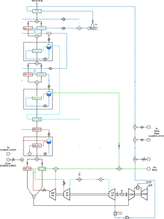
H2-IGCC Steam Cycle is similar to that given in figure 1.21. 300MW F Class Gas Turbine fed a horizontal three pressure level Heat Recovery Steam Generator. Produced Steam is sent to three turbine bodies (HP, IP, LP) and re-superheating takes place between HP steam turbine and IP steam Turbine.
Fig. 1.21: Scheme of SGT6-5000F three pressure level with drum type evaporator combined cycle [23]
An analysis of the present of the combined cycle based on the Best Available Technology of the F, G, H Gas Turbine has been carried out [25]. In figure 1.22 and 1.23 are reported some specification about the steam mass flow, the steam properties (temperature, pressure), the number of the pressure levels, the circulation system, the overall power and the installation year of the plant. (Blue HRSG is vertical type, Red HRSG is horizontal type).
It can be notice that to improve the efficiency of the plant, according to the plant specifications (power and heat demands), the number of pressure level is usually set to be equal to 3: High Pressure (some 120-160bar), Intermediate Pressure (some 20-50 bar) and Low pressure (some 3-7 bar). Steam mass flows and temperatures are different in relation with the integration level of the plant
Pag. 46 of 202
Fig. 1.22: Existing Plant Specification
Pag. 47 of 202
1.3.2.1 HRSG
Typical layout Heat Recovery Steam Generator adopted in the combined sections of IGCC power plants are schematically given in figure 1.24. Horizontal and Vertical HRSG are depicted.
Fig. 1.24: Isometric View of 3PL-Drum Type HRSG – Horizontal and Vertical Type
H2-IGCC heat recovery steam generator is a horizontal one equipped with drum type evaporator and with finned tube banks. Non-condensable are extracted by the adoption of a Tray-type deaerator. In figure 1.25, typical horizontal three pressure level HRSG is given.
Pag. 48 of 202 Comparison between Benson and Drum evaporator has been carried out and according with the plant specifications the adoption of conventional drum type boiler has been selected. In figure 1.26, the two options are given [23].
Fig. 1.26: Scheme of Conventional Drum VS Benson Once Through Boiler [23]
Super-heater, economizer and boiler tube bundles are finned tube type. Such a solution is typically adopted in these kinds of power plants. Adoption of finned tube banks leads to increase the external heat transfer coefficients and to improve the heat transfer phenomena. Typical HRSG finned tube banks layout is given in figure 1.27.
Pag. 49 of 202
1.3.2.2 Steam Turbine
Steam Turbine adopted in such IGCC power plants is similar to the SST5-5000 and to the SST5-3000. Three turbine bodies with a Re-heating between HP and IP ST are employed in the plant to increase the power driven by the steam turbine. A cross section of the SST-3000 is given in figure 1.28.
Fig. 1.28: Cross Section of SST5-3000 Steam Turbine [26]
According with [27], adoption of SST-5000 and SST-3000 allows to connect the steam turbine and gas turbine to the same electric generator. Such a solution is schematically plot in figure 29.
Pag. 50 of 202
1.3.2.3 Condenser
‘Cold cooling water results in a low condenser back pressure. Therefore a steam turbine with a huge exhaust area is needed. For these locations, Siemens can provide a single shaft RPP with a double flow LP steam turbine.’[27].
According with the plant specification and with the H2-IGCC project context the condenser is a surface cooling water system fed by sea water. Condensing pressure has been assumed, according also with some manufacturer declaration at 2.5mbar. In figure 1.30 a schematic view of the condenser is given.
Pag. 51 of 202
1.4 Reference
[1] - Xu Zhaofeng, Jens Hetland, Hanne M. Kvamsdal, Li Zheng, Liu Lianbo, “Economic evaluation of an IGCC cogeneration power plant with CCS for application in China”, Energy Procedia 4 (2011) 1933–1940
[2] - “Wabash River Coal Gasification Repowering Project: A DOE Assessment”, Report N. DOE/NETL-2002/1164, 2002.
[3] - “Tampa Electric Integrated Gasification Combined-Cycle Project. A DOE Assessment”, Report N. DOE/NETL – 2004/1207, 2004.
[4] - “IGCC Puertollano. A clean coal gasification power plant”, published by ELCOGAS [5] - NETL Gasifipedia - Gasification in Detail, available on 28th of July, 2011, at:
http://www.netl.doe.gov/technologies/coalpower/gasification/gasifipedia/6-apps/6-2-6-4_nuon.html
[6] - Energy for sustainable future, on 28th of July, 2011, at:
http://energy-21.blogspot.com/2010/11/nakoso-igcc-plant.html
[7] - Ishibashi, Y., Shinada, O., “First year operation results of CCP’s Nakoso 250 MW air-blown IGCC demonstration plant”, Gasification Technologies Conference, Washington DC, USA, 2008.
[8] - Higman, C., van der Burgt, M.,,”Gasification”, Gulf Professional Publishing, Elsevier, 2nd Edition, 2008.
[9] - http://www.h2-igcc.eu/default.aspx
[10] - Nikolett Sipöcz, Mohammad Mansouri, Peter Breuhaus & Mohsen Assadi, “Plant specification and detailed thermodynamic performance analysis of selected IGCC cycle”, H2-IGCC Report, October 2010
[11] - Department of Mech. & Structural Eng. & Material Science, University of Stavanger , “IGCC State of the art report, a part of EU-FP7 Low Emission Gas Turbine Technology for Hydrogen-rich Syngas ”, H2-IGCC Report, April 2010
[12] - Ansaldo Energia Brochure AE94.3A GAS TURBINE; Genoa, Italy; May 2012. [13] - SIEMENS AG, Siemens Gas Turbine SGT5-4000F. Answers for energy, 2008.
[14] - SIEMENS AG, Compressor Mass Flow Increase Upgrade for SGT5 – 4000F Gas Turbines, 2008.
[15] - SIEMENS AG, Siemens Gas Turbine SGT6-5000F, Answer for Energy, 2008
[16] - SIEMENS AG, Latest performance upgrade of the Siemens gas turbine SGT5 – 4000F, Answer for energy, 2008
Pag. 52 of 202 [17] - Jonsson M., Bolland O., Bucker D., Rost M. (Siemens), 2005, ‘Gas Turbine Cooling Model for Evaluation of Novel Cycles’. Proceedings of ECOS 2005, Trondheim, Norway, June 20-22, 2005.
[18] - Giuffrida A., Romano M. C., Lozza G. G., 2010, ‘Thermodynamic assessment of IGCC power plants with hot fuel gas desulfurization’. Elsevier, Applied Energy 87 (2010), ppg. 3374 – 3383.
[19] - Kim Y.S., Lee J. L., Kim T.S, Sohn J.L., Joo Y. J., 2010: ‘Performance analysis of a syngas-fed gas turbine considering the operating limitations of its components’, Elsevier, Applied Energy 87 (2010), ppg. 1602-1611.
[20] - Final Report of the RTO Applied Vehicle Technology, 2007: ‘Performance Prediction and Simulation of Gas Turbine Engine Operation for Aircraft, Marine, Vehicular, and Power Generation’
[21] - Ashok Rao., 2010, ‘1.3.2 Advanced Bryton Cycles’
[22] – Walter H., Hofmann R., 2010: ‘How can the heat transfer correlations for finned-tubes influence the numerical simulation of the dynamic behavior of a heat recovery steam generator?’, Accepted Manuscript, Applied Thermal Engineering.
[23] - SIEMENS AG, Siemens Gas Turbine SGT6-5000F, Application Overview, 2008 [24] – Noordermeer J., Gryphon International Engineering Service Inc.
[25] – CMI Energy, Horizontal &Vertical HRSGs Reference List, Cockerill Maintenance & Ingénierie.
[26] – Siemesn AG 2010: ‘Siemens Steam Turbine SST-3000 Series for combined cycle application’.
[27] – Emberg H., Alf M., SCC5-4000F Single Shaft (SST5-5000): ‘A single shaft concept for cold cooling water conditions’.
[28] - Xu Zhaofeng, Jens Hetland, Hanne M. Kvamsdal, Li Zheng, Liu Lianbo, “Economic evaluation of an IGCC cogeneration power plant with CCS for application in China”, Energy Procedia 4 (2011) 1933–1940.
Pag. 53 of 202
Chapter II
Modelling Approach and Solution Strategy
2.0 IntroductionIn order to evaluate the IGCC plant operating maps and to establish appropriate control policies, a steady state plant simulator has been set up. The H2-IGCC plant has been developed taking two macro island into consideration: Gasification Island (GI) and Power Island (PI).
The Gasification Island (GI) is made of many components such as the Gasifier, the Syngas Cooler and so on. GI simulator has been developed by the assumption of component models based on empirical correlations taken from the State of the Art (SoA), connecting the inputs to the outputs. Connections between the Power Island (PI) and the Gasification Island have been established taking the above empirical correlations into consideration. Chemical reactions have been considered at equilibrium.
On the other hand, looking at the PI, detailed models have been adopted in order to described Gas Turbine (GT) and Steam Cycle (SC) macro components. Using such a modelling approach a simulator has been established. The simulator is a detailed replica of the various machines and equipment’s and it has been adopted to map the plant performance, evidencing dangerous behaviour (i.e. GT over-pressures, over-temperatures, shaft over-load, etc.) under various operating conditions and loading.
In the following paragraphs, description of the modelling approach and the solution techniques is given.


![Fig. 1.26: Scheme of Conventional Drum VS Benson Once Through Boiler [23]](https://thumb-eu.123doks.com/thumbv2/123dokorg/2840699.5133/48.892.242.646.201.507/fig-scheme-conventional-drum-vs-benson-boiler.webp)