ICM11
Vibration based diagnostics on rolling contact fatigue test
bench
L. Solazzi
a*, C. Petrogalli
aand M. Lancini
aaUniversity of Brescia, Department of Mechanical and Industrial Engineering, via Branze, 38, 25123 Brescia – Italy
*Corresponding author. Tel. +39 030 371 5577; fax: +39 030 371 5942 E-mail address: [email protected]
Abstract
The paper presents the first results of a study on vibrations associated with a rolling contact fatigue test bench and how this mechanical behavior may be correlated to the fatigue damage of the specimens. In particular, the aim of this study was to evaluate the possibility to detect and quantify, thanks to vibration analysis, the damage on two discs subjected to rolling contact fatigue. The first part of this work regards a description of the bench with a focus on the results acquired by its static and modal fem analyses. Then, some pure rolling and sliding condition tests were carried out and a procedure to monitor both the specimens damage state and to record accelerometric data was implemented by placing a set of piezoaccelerometers on the machine and developing a virtual instrument for automatic data handling and analysis. Tests were also periodically stopped and the rolling contact surface profile was acquired by means of a linear video camera in order to evaluate its progressive damage. Data acquired were analyzed, considering also the results from the first part of work, both using a standard approach, such as a spectral analysis (FFT, PSD and waterfall), and by implementing custom digital weighting filters for a windowed RMS in order to estimate, realtime during the measurement, a good estimator for the specimen damage state development.
Keywords: vibration, damage detection, RMS, industrial diagnostics, rolling contact fatigue.
1. Introduction
Rolling contact fatigue is a typical phenomenon that affects mechanical components such as bearings, cams and gears during working conditions and plays a fundamental role in railway field with regard to damage in wheel rail contact [1-2-3]. As is known in some cases the failure of these components has serious consequences. For this reason, since the past it has been tried to reproduce this phenomenon in laboratory through the design of test benches [4] able of simulating the real operating conditions of components subjected to rolling contact fatigue in order to study the damage and make prediction models. Therefore it becomes necessary to have tools to monitor the tests that allow to find variables useful to the
doi:10.1016/j.proeng.2011.04.571 Procedia Engineering 10 (2011) 3465–3470
1877-7058 © 2011 Published by Elsevier Ltd.
Selection and peer-review under responsibility of ICM11
Open access under CC BY-NC-ND license. © 2011 Published by Elsevier Ltd.
Selection and peer-review under responsibility of ICM11
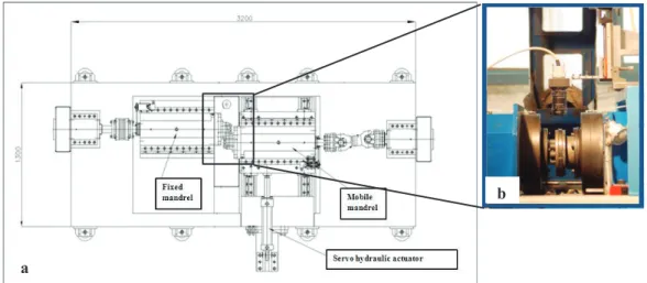
The object of this study, showed in fig. 1a, is a high performance rolling contact fatigue test bench. It is a bi-disk machine designed and built at the Department of Mechanical and Industrial Engineering of University of Brescia and dedicated to test and study the interactions between two components subjected to cyclic contact in different working load conditions. It is equipped with two independent mandrels driven by a.c. engines of 33 kW coupled with a two stages planetary gearbox and fixed transmission timing belt pulley. One of the mandrels can translate on linear slides and it is moved by a servo-hydraulic actuator that allows also the contact load application (up to 70kN). Specimens are disc shaped and their diameter, thickness and radius of curvature can vary within a range in order to study the eventual scale effect. The system offers high flexibility and precision and allows to set and independently control the rotating speed of the samples (up to 1000 r.p.m.) or engine torque and the contact force. There is also the possibility of performing tests in dry or lubricate (water or oil) conditions. The machine is controlled by software that allows to remotely set and continuously monitor all operating parameters, thereby enabling an even diagnostic of the damage of the specimens. Finally the bench is equipped with an image acquisition system that, by means of high-resolution (1m) line scan camera, can capture images of the rolling surfaces tracking the evolution of the damage of the samples (fig.1b).
Fig. 1. Test bench: (a) schematic draw; (b) Image acquisition system .
The test bench is made by welding of different sections in commercial S355JR UNI 7729, its dimensions are approximately 3200x1300x1000 mm and its total weight is about 5500 kg. The solid model of the structure is shown in the fig. 2.
a
Fig. 2. Solid model of test bench.
3. Numerical Analysis
The purpose of this paragraph is to evaluate both static and dynamic behavior of the bench through numerical analysis and, in particular, to determine the stresses and displacements at the maximum applied force and the first natural frequencies of the bench.
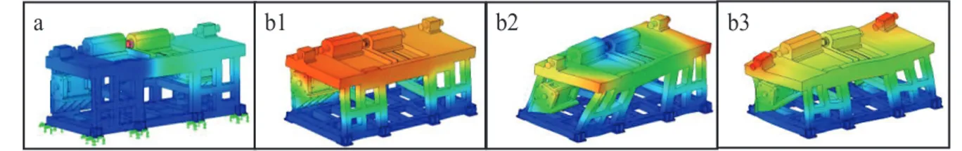
To identify in which frequency range useful information could be gathered, a preliminary analysis using a FEM software has been performed. From such analysis not only natural frequencies of the test bench were found, which were then confirmed by a series of accelerometric measurements, but also mode shapes involved which were used to identify the most suitable number and position of accelerometers to be used for a continuous monitoring. Figures below show the results of the analyses performed at the maximum applied force (fig. 3a) between the specimens and at the first three vibration modes assuming a linear elastic structural behavior for the bench. In particular, figures 3b shows that the first mode shape, which corresponds to a frequency of 53.3 Hz is the most important because the others are very peripherals and therefore not useful for the accelerometer investigation. As can be clearly noticed the first mode shape display deformation highly localized near the specimen itself, while the others only involve marginal participation of the specimen in vibration, therefore accelerometer information is sought only closer to the specimen itself, and at frequencies closer to 50Hz.
Fig. 3. FEM analyses results: (a) Deformed shape at maximum applied load F=70kN; max displacement = 0,01 mm; ( b1) Deformed shape at first vibration mode (f=53.3 Hz); (b2) Deformed shape at second vibration mode (f=79.9 Hz); (b3) Deformed shape at third vibration mode (f=121.1 Hz).
4. Experimental Analysis
In order to highlight and then monitor the damage that occurs in components subjected to rolling contact fatigue some tests in pure rolling and sliding conditions varying specimens dimensions, rolling speed and
Fig 4 . Accelerometers position.
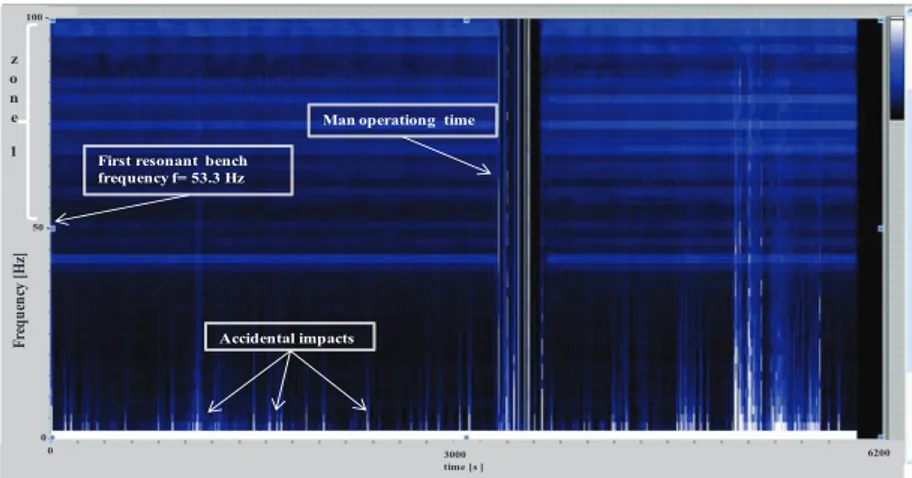
Since first experimental tests have pointed out high variability in the higher frequency range, which makes difficult a reliable evaluation of damage progression, a set of time-frequency analysis (using a waterfall representation, as can be seen in fig.5) has been performed, and showed that intensity of vibrations in the range below the first resonant frequency is less influenced by actuators presence and environmental noise and bench resonant mode shapes interference whose frequencies range is indicated as zone 1. For these reasons a lowpass filter isolating frequency lower than 43Hz has been inserted before RMS evaluation.
Fig. 5 . Waterfall diagram.
a
First resonant bench frequency f= 53.3 Hz
Accidental impacts
Man operationg time
100 50 -0 Freq uen cy [Hz] z o n e 1 3000 time [s ] 6200 0
A further issue that waterfall analysis pointed out is the high sensitivity to events typical of the low controlled environment such as accidental impacts, temperature and noise sudden variation and variable human presence. In fig. 5 it is also visible the man operating time during which, the rolling speed of engine and load application are firstly reduced and then restored soon. Hence the generation of singular impacts concentrated in a short period of time that is not index of damage and should be neglected. To avoid false reading and misinterpretation of the RMS as damage indicator, a running exponential averaging filter, described with the equation 1, has been implemented, to increase sensitivity with respect to permanent variation in the RMS level, while offering a reduced weight to occasional accidental events.
This is achieved by computing equivalent acceleration at time tj as :
j i t t j i i t t j e a e t a j i j i 0 ) ( 0 ) ( *() (1)
where Į = 0,5 s-1 is constant reciprocal to settling time coefficient [5].
The final damage indicator is therefore computed by acquiring acceleration data at a 5kHz sampling frequency from each accelerometer using 0.5s consecutive windows; for each window a weighted RMS is computed thanks to a lowpass filter set to the aforementioned cutoff frequency of 43Hz, and evaluated using a mobile exponential averaging filter.
This indicator has been successfully used to monitor damage progress in a set of specimens under test, showing a common repeatable behaviour, which is clearly depicted by figures 6. In particular the results are referred to pure rolling water lubricated tests carried out on steel specimens. Rolling speed was set on about 500 r.p.m. and the contact pressure was varied between 1500 MPa to 2500MPa. Tests have been monitored continuously for all their duration and periodically an acquisition of ten minutes was recorded and elaborated until the appearance of spalling phenomenon. Therefore they lasted several days.
Fig. 6 . Rolling contact fatigue test acquisition : (a) RMSe diagram; (b) Waterfall diagram; (c) Rolling contact surfaces number of acquisition [n] RM Se [m /s 2] phase 1 Failure phase 2 phase 3 40 -20 0 F re que nc y [ H z] 12000 time [s ] 24000 0 1.4 0.9
0 cycles phase 1 phases 2-3 Failure
c a
b
increase in vibrations and noise [10].
5. Conclusions
A first study on rolling contact fatigue test bench vibrations and a possible way to detect and quantify damage on the specimens using vibrations analysis was presented. In particular according with the results acquired by both static and modal fem analyses and by experimental test using a specific test bench. A set of piezoaccelerometers were placed on the machine and a virtual instrument for automatic data handling and analysis was developed. Data acquired were analyzed both using a standard approach and by implementing custom digital weighting filters for a windowed RMS and a similar behavior for all specimens tested was found. Finally the supposition explaining its characteristics have been confirmed, at a preliminary level, thanks to surface image analysis performed by a high resolution linear video camera in parallel with vibration recordings. Furthermore, the vibration level computed as explained has been successfully used as a damage level indicator for test bench monitoring purposes. Apart from increasing the statistical base on which the vibration level/damage correlation proposed has been validated, further development of this work which are actually being evaluated are the automatic synchronization of video recording of surfaces with acceleration measurement in order to describe damage progression more in detail, and the introduction of artificially created damages on the specimen to associate known damages pattern with noticeable vibration level behavior.
References
[1] Nélias D, Dumont ML, Champiot F, Vincent A, Girodin D, Fougères R, Flamand L. Role of inclusions, Surface Roughness and Operating Conditions on Rolling Contact Fatigue. Trans of the ASME 1999; 121: 240-251.
[2] Tyfour WR, Beynon JH, Kapoor A. Deterioration of rolling contact fatigue life of pearlitic rail due to dry-wet rolling-sliding line contact. Wear 1996; 197: 255-265.
[3] Bormetti E, Donzella G, Mazzù A. Surface and subsurface cracks in rolling contact fatigue of hardened components. Tribology
Transactions 2002; 45; 3:274-283
[4] Cambiaghi D, Donzella G, Isceri A. Progetto di un banco prova per lo studio di fenomeni di contatto cicilico. Il Progettista
Industriale Novembre 2003.
[5] Bendat, JS, Piersol AG. Engineering Applications of the Correlation and Spectral Analysis. Wiley-Interscience Publication, 1993.
[6] Heylen W,Lammens S, Sas P. Modal Analysis Theory and Testing, Katholieke Universiteit Leuven, 2007 [7] Oppenheim, A. V. et al, Discrete-Time signal processing, Prentice Hall, 1999
[8] Doebling SW et al. A summary Review of Vibration-Based Damage Identification Methods, The shock and Vibration Digest 1998;30;91
[9] Farrar C.R. e al., Vibration-based structural damage identification, The royal Society, 2001.
[10] Donzella G., Mazzù A., Solazzi L., Study of the rolling contact fatigue in lubricated contacts, Proceedings of the World
![Fig. 6 . Rolling contact fatigue test acquisition : (a) RMSe diagram; (b) Waterfall diagram; (c) Rolling contact surfaces number of acquisition [n]RMSe [m/s2]phase 1Failurephase 2phase 340-20 0Frequency [Hz]12000 time [s ]2400001.4](https://thumb-eu.123doks.com/thumbv2/123dokorg/5515198.64035/5.841.140.674.588.893/rolling-acquisition-waterfall-rolling-surfaces-acquisition-failurephase-frequency.webp)
