Research Article
Sensitivity to Damage Imperfection for Multileaf Masonry Walls
Based on Vibrational Analyses
G. Boscato ,
1E. Reccia ,
2D. Baraldi ,
3and A. Cecchi
31LabSCo, IUAV University of Venice, Venice, Italy 2DISG, Sapienza University of Rome, Rome, Italy 3DACC, IUAV University of Venice, Venice, Italy
Correspondence should be addressed to G. Boscato; [email protected] Received 30 May 2018; Accepted 22 July 2018; Published 13 September 2018 Academic Editor: Yuri S. Karinski
Copyright © 2018 G. Boscato et al. This is an open access article distributed under the Creative Commons Attribution License, which permits unrestricted use, distribution, and reproduction in any medium, provided the original work is properly cited. Damage-imperfection indicators based on variation of dynamic parameters allow to identify the intrinsic discontinuity and the damage of structures. Here, the structural health monitoring through the vibration-based approach has been carried out by two steps on three different multileaf masonry specimens (full infill, damaged infill, and strengthened infill) subjected to uniaxial compressive load. In the first step, the characterization of initial conditions based on the investigation of the intrinsic discontinuity and the manufacturing imperfections has been done. In this phase, the detection, localization, assessment, and prediction of damage have been given by the comparison between the experimental and numerical modal data calculated by the commercial finite element code. Subsequently, in the second step, starting from the identification of undamaged condition, the damage effects on changes of the dynamic parameters have been recorded. As well known, the incoherent response between the leaves is related to frequency values, damping ratios, and modal shapes.
1. Introduction
The process of implementing the damage identification strategy for structures is referred to as structural health monitoring (SHM). Damage is defined as any change af-fecting the performance of a system [1]. In the framework of civil structures, damage can be related to changes occurring to material or geometric properties which may lead to nonlinear behavior, but also to degradation of elastic stiff-ness, loss of mass, or changes in the boundary conditions. From this perspective, also imperfections and presence of defects may be included in damage. The attention to SHM has constantly grown in the last decades: several non-destructive monitoring techniques have been developed with the purpose of identifying damages in structures. Among the
various tools available to perform nondestructive
SHM—such as ultrasonography, thermography, and
X-ray—recently, methods based on the global vibration response of the structure have aroused great interest, which has been shown by the wide literature regarding this subject
[2, 3]. Damage in a structure leads to modification of the vibration modes, manifested as changes in the modal pa-rameters: natural frequencies, mode shapes, and modal damping. Modal testing and system identification tech-niques allow to easily and cheaply extract the modal pa-rameters from the measured vibration response. Assuming that ambient conditions do not significantly affect the system properties, measured changes in the vibration response can be associated with structural damage: degradation of stiff-ness, alteration of the mass, and/or the damping distribution.
Usually, damage identification methods based on vi-bration responses have been used for the monitoring of steel or concrete structures, such as long bridges or tall buildings, where the relative homogeneity of materials or the structural typology are particularly suitable for vibration analysis. However, in the last fifteen years, their application has in-terested also masonry structures [4], in particular the his-torical architectural heritage [5–7]—mainly composed of masonry buildings—thanks to their nondestructive nature
Volume 2018, Article ID 2321589, 14 pages https://doi.org/10.1155/2018/2321589
and to their possibility of not providing direct access to the damaged zone, which may be very important in case of natural disasters such as seismic events [8–12]. The adoption of combined historical and architectural surveys together with dynamic investigations allows realizing reliable nu-merical models able to describe the actual behavior of cultural heritage and, in case of alteration of the vibration response, to identify possible damage or imperfections and to predict future structural behavior [13, 14].
Laboratory tests have been proposed to improve methodologies for dynamic identification and damage de-tection of existing masonry structures, both on full-scale masonry buildings [15] and on masonry wall panels [16, 17], with attention focused on damage indicators. In particular, in the work [17], damage has been specifically induced in a masonry panel and the modal response of the specimens has been extracted in order to evaluate the structural health for different levels of damage, with the purpose of detecting possible correlations between variations in the modal properties and the entity of the damage.
In our study, attention is focused on multileaf masonry walls. The research is part of a wider project devoted to the mechanical characterization of multileaf masonry walls by means of experimental tests [18, 19] and numerical analyses [20, 21]. Several specimens of multileaf masonry walls have been realized and tested in the laboratory up to collapse at the LabSCo (the Laboratory of Strength of Materials of the University IUAV of Venice, Italy). During the compressive tests, dynamic measures have been collected with the twofold target of calibrating the numerical models and evaluating the change of modal parameters under different conditions.
Multileaf is one of the most widely diffused typologies of the historical constructive technique for masonry walls. It is a multilayered wall, usually composed of two external leaves made of bricks or stones containing an internal cavity filled up with the incoherent material, usually made with a mix-ture of scraps coming from the construction site, such as brick potsherds, broken shingles, stones, cobblestones, and mortar. Its wide diffusion in the historical architectural heritage claims to the necessity of accurate studies, in particular aiming at an effective evaluation of mechanical properties and structural behavior.
The mechanical behavior of multileaf masonry walls is strongly dependent on the different mechanical properties of the leaves. In particular, the different stiffness of the external bearing walls and the weaker internal core may or may not determine the load distribution between the leaves [22, 23]. The behavior is strongly affected by constructive features, such as the mechanical properties of constituent materials, the thickness of the leaves, and presence or absence of “diatoni,” that may lead to the lack of connection between the leaves. Several experimental studies on multileaf walls can be found in the scientific literature [24, 25], mainly related to the effect of strengthening [26–29] and to the modelling strategies able to properly describe the global behavior of multileaf masonry walls [30–32].
A crucial role is played by defects and manufacturing imperfections—quality of the internal filling, distribution of mortar, presence of voids, etc.—and by the several
uncertainties related to the geometric configuration and the state of conservation. In this work, dynamic identification with the output-only methodology [4, 33] is proposed with the specific target of determining the dynamic parameters of multileaf masonry walls subjected to increasing uniaxial compressive load. The dynamic identification was carried out by means of the output-only methodology, and the data were processed through the least-square complex frequency (LSFC) estimator by the LMS PolyMax algorithm [34]. In order to investigate the presence of imperfections and damage, three different types of multileaf masonry specimens have been analyzed: (i) regular panels with full infill, (ii) panels with imperfections with damaged infill, or (iii) panels with imperfections with consolidated infill. With respect to the previous work [20], here attention is focused on the evolution of the damage during the tests, identified by changes in the modal parameters extracted in correspondence of three different steps of load provoking increasing damage. The intrinsic discontinuity of multileaf and the manufacturing imperfections are amplified by the incremental damage: by the comparison between the data of the initial conditions and the evolution during the tests, it is possible to detect the anomalies and the intrinsic vulnerabilities.
The outline of this paper is as follows: in Section 2, the mechanical characterization of the constituent materials adopted in the realization of the specimens is provided. In Section 3, the different typologies of multileaf specimens and the tests performed in the lab are described. Section 4 deals with the dynamic identification: initial conditions are an-alyzed both experimentally and numerically, and then a comparison with the evolution of damage during the tests is performed in terms of changes in the modal parameters. Finally, in Section 5, some final remarks are provided.
2. Mechanical and Physical Tests of the
Constituent Materials
2.1. Flexural and Compressive Tests on Mortar Samples.
For the laboratory tests on mortars, specimens were pre-pared in accordance with the EN 1015-11. Different types of mortars have been tested. A special mortar has been realized in collaboration with Tassullo Materiali S.p.A. (note: ref-erence is made to a manufacturer’s product for the purposes of factual accuracy. No endorsement is implied) in order to simulate a historic hydraulic lime mortar, namely, type CP/5. This mortar has been used in the construction of masonry specimens both for joints and for the infill. Other two typologies of mortar (TD13C and TD13SRG) with higher structural performance have been used for the top and bottom layers of masonry specimens.
Several tests were performed at LabSCo (IUAV). For each type of mortar, sets of 3 prismatic specimens, sized 160 × 40 × 40 mm, have been prepared. At first, tests were performed for determination of flexural strength. After the breaking of specimens, both halves were analyzed under normal load. Mechanical characteristics obtained by flexural
tests and compressive tests are listed in Table 1. FF is the
maximum load of the flexural test, while FCis the maximum
ftm�average flexural strength, fc1 and fc2�compressive
strengths of each half, and fcm�average compressive
strength.
2.2. Compressive Tests on Brick Samples. After the
experi-mental tests on mortars, compressive tests were performed also on brick specimens. For this research, new standard
bricks (Danesi DM116), sized 250 × 120 × 55 mm3, were used
(note: reference is made to a manufacturer’s product for the purposes of factual accuracy. No endorsement is implied), in accordance with UNI 12.6.25. The tests were performed on 3 specimens with the Galdabini universal testing machines (200 kN), appointed with B-1, B-2, and B-3. For all of them, the elastic modulus was evaluated experimentally, and the results are reported in Figure 1. Through the linear branch of an average curve, the elastic modulus has been determined to be equal to 4000 MPa.
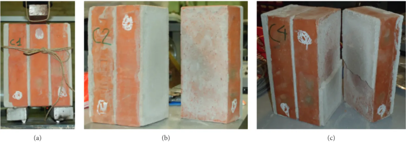
2.3. Determination of Initial Shear Strength. Nine specimens
were prepared in accordance with UNI EN 1052-3 and subject to the load application in the Galdabini universal testing machines (200 kN) to analyze the initial shear strength. The tests were performed according to the process B (UNI EN 1052-3), which does not include the prestress condition of the samples. The results are reported in Table 2, and all the specimens presented the type of failure A1 (UNI
EN 1052-3) (Figure 2). In detail, the shear failure mode A1 (1) is in the area of the union brick element/mortar on a surface of the brick element, while the shear failure mode A1 (2) is in the area of the union brick element/mortar between two sides of the brick element (Figure 2 and Table 2).
3. Characteristics of Masonry Walls and Test
This research follows and develops a topic addressed pre-viously in [18, 20]. Several multileaf masonry panels
Table 1: Mechanical characteristics of mortar samples.
Mortar type Flexural tests Compressive tests
FF(N) ft(MPa) ftm(MPa) FC(N) fc1(MPa) fc2(MPa) fcm(MPa)
CP/5 130 0.299 0.330 2294 — — 1.162 172 0.389 1495 0.921 0.676 133 0.301 2118 1.315 1.269 TD13C 888 2.010 1.859 14366 8.790 8.746 9.024 538 1.224 14979 9.169 8.411 1054 2.343 14252 8.892 10.135 TD13SRG 1136 2.637 2.571 10225 6.372 6.310 6.539 1003 2.299 10187 6.265 6.677 1189 2.776 10743 6.703 6.908 0 5 10 15 20 25 30 0 0.002 0.004 0.006 0.008 0.01 0.012 σ ε B-1 B-2 B-3 Average
Figure 1: Diagram of σ-ε of compressive tests on bricks.
Table 2: Maximum load (Fi,max) and the related shear strength (fv0,i)
for each triplet and average value (fv0).
Specimens Max load
Fi,max(N) Types of failure fv0,i (MPa) fv0 (MPa) C1 15792 A1 (2) 0.275 0.187 C2 27747 A1 (1) 0.488 C3 13268 A1 (2) 0.236 C4 11562 A1 (2) 0.203 C5 782 A1 (1) 0.014 C6 7591 A1 (1) 0.134 C7 1282 A1 (2) 0.023 C8 8877 A1 (2) 0.158 C9 8882 A1 (1) 0.156
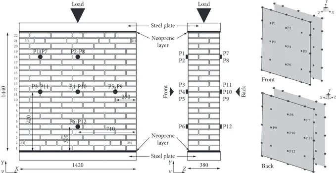
characterized by three different typologies of infill—full, damaged, and consolidated, as illustrated in Figure 3—have been tested by applying uniaxial compressive load, as shown in Figures 4 and 5. In detail, Figure 3 shows the three different infill typologies considered. The panels consist of two external leaves of periodic masonry and an inner core made of brick potsherds mixed with mortar. In the case of full infill (B1), the core has been completely filled up, while for the other typologies, only the upper one-third and lower one-third of the whole mass were completely filled up, in order to simulate the presence of defects or damages in the central part. In the case of damaged infill (B2), only brick potsherds without mortar constitute the central area, while for the consolidated typology (B3), the same part has been strengthened by a consolidating mixture.
The physical and mechanical characteristics of every material have been detailed in [20].
Figure 4 shows the setup of the compressive test carried out on masonry panels. All compression tests were
performed on a 6000 kN capacity loading machine with the data control system (Figure 5(a)); the loading velocity was taken as 0.03 mm/s with the displacement control pro-cedure. The compression load was applied through a loading history made up of three loading steps until the failure. Each loading step (thresholds A, B, and C in Figure 5(b)) was followed by a pause period of 10 minutes where the reached compression loads are kept constant. In detail, step A corresponds to the initial condition without the external load, the threshold of step B is 700 kN, while the threshold of step C is 1500 kN (Figure 5(b)).
The vibration signals have been recorded through the accelerometer sensors widely described in [20].
4. Structural Identification Based on
Vibrational Data
The variation of dynamic parameters, modal shapes, fre-quencies, and damping ratios increasing the compressive
(a) (b) (c)
Figure 2: Specimen test (a); failure mode A1 (1) (b); failure mode A1 (2) (c).
Section a-a R R 1440 20 3 120140120 (a) 20 15 9 3 Section a-a R R 390 390 390 120140120 (b) 20 15 9 3 390 390 390 Section a-a R R 120140120 (c)
Figure 3: Different typologies of masonry specimens: (a) B1-full infill; (b) B2-damaged infill; (c) B3-consolidated infill (dimension in millimeters).
load and changing the damage patterns has been analyzed. The steps B and C correspond to 35% and 75%, respectively, than to the mean value of failure load. The different dynamic parameters of every load step have been analyzed and compared; in detail, the values of step A characterize the intrinsic imperfection of multileaf masonry panels at the undamaged state [20], while the identified parameters of steps B and C allow to quantify the damage effects.
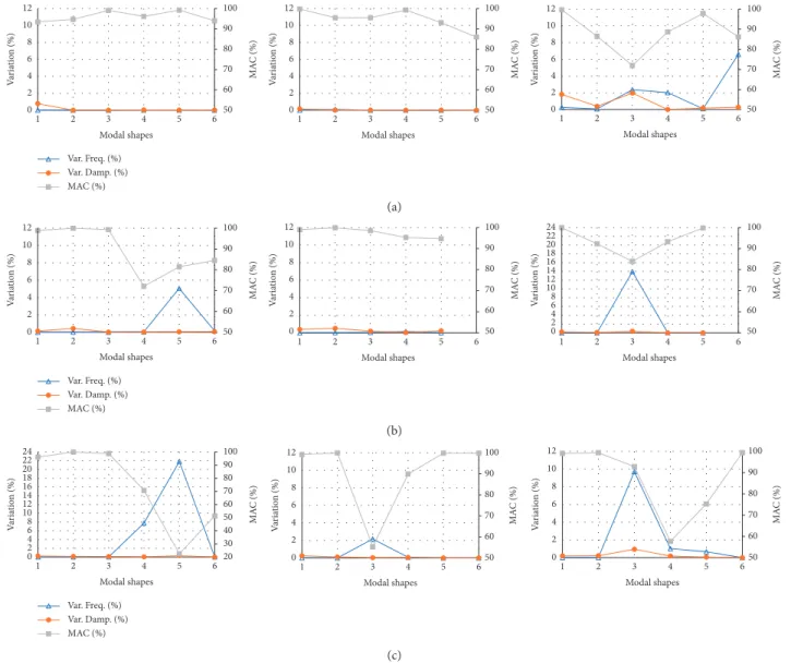
4.1. Step A: Imperfection Identification. The first analysis of
multileaf masonry panels has been carried out without the compression load, step A (Figure 3(b)). The imperfection indicators have been evaluated by the variation of frequency (var. freq.), variation of damping ratio (var. damp.), and MAC [35] values between the two external layers that constitute the multileaf masonry panels (“front” and “back” in Figure 4). 3/4 3/4 1/4 1/4 1 2 3 4 5 6 7 8 9 10 11 12 13 14 15 16 17 18 19 20 21 22 Y X Z P1 P2 P3 P4 P5 P6 Y Z X P8 P9 P10 P12 P11 P7 Load Load Steel plate Steel plate Neoprene layer Neoprene layer P1 P1-P7 P2-P8 P3-P11 P4-P10 P6-P12 710 1420 380 X Y Z Z Y X 720 Front Back 1440 300 P5-P9 250 P2 P7P8 Front Back P3 P4 P5 P6 P11 P9 P10 P12
Figure4: Scheme of the test setup (dimension in millimeters).
(a) 0 500 1000 1500 2000 2500 Lo ad (kN) 0.5 1 1.5 2 2.5 3 0 Vertical displacements (mm) B1-1 B1-2 B1-3 B2-1 B2-2 B2-3 B3-1 B3-2 B3-3 (b)
These indicators allow to define the global and/or local behavior of every multileaf masonry panel. In detail, if an MAC value is lower than 90%, a discordance between both layers of multileaf masonry panels detecting uncoupled and/or local modal shapes is identified.
The MAC parameters is compared with the frequency and damping variations to identify the absence of global behav-iour (when the frequency and damping variations between the two layers of multileaf masonry panels are less than 1%). The observance of these three indicators (frequency
variation and damping variation ≤1% and MAC ≥90%) is
able to identify the consistency and homogeneity of speci-mens and then the global behavior. Instead, the non-compliance of these indices detects the uncoupled modal shapes. These thresholds have been identified in Figure 6 by black arrows, while the exceeding of the limits has been highlighted locally by the red arrows.
The main global responses have been labelled by 1st_B,
1st_T, and 2nd_B to identify, respectively, the 1stbending,
1sttorsional, and 2ndbending modal shapes.
For the full infill multileaf masonry panels (B1), only one (B1-3) shows the intrinsic imperfection to the initial con-dition, step A. In detail, the values that exceed the limits concern the modal shapes 3, 4, and 5 (Figure 6(a)).
The damaged infill of B2 typology (Figure 6(b)) causes decoupled modal shapes due to the independent behavior of the three layers of multileaf masonry panel, core, and outer layers. B2-2 shows a better global behavior than B2-1 and B2-3 characterized by imperfection indicators greater than the limit by 1% for the frequencies and MAC values lower than 90%.
Consolidating for the B3 masonry panels (B3; Figure 6(c)) is not efficacious: the behavior between “front” and “back” is different for all three masonry panels of B3; the imperfection indicators are out of the limit for every panel.
The imperfection effects on global structural perfor-mances of the three typologies, B1, B2, and B3, are shown in Figure 7. In detail, the structural behavior is affected by the intrinsic imperfection when the indicators are out of the limit above all in the first three modal shapes.
Var. Freq. (%) Var. Damp. (%) MAC (%) 0 2 4 6 8 10 12 V ar ia tio n (%) 2 3 4 5 6 1 Modal shapes 50 60 70 80 90 100 MA C (%) 0 2 4 6 8 10 12 V ar ia tio n (%) 2 3 4 5 6 1 Modal shapes 50 60 70 80 90 100 MA C (%) 0 2 4 6 8 10 12 V ar ia tio n (%) 2 3 4 5 6 1 Modal shapes 50 60 70 80 90 100 MA C (%) (a) 100 22 24 100 12 100 10 12 Var. Freq. (%) Var. Damp. (%) MAC (%) 50 60 70 80 90 MA C (%) 2 3 4 5 6 1 Modal shapes 0 2 4 6 8 10 12 14 16 18 20 V ar ia tio n (%) 50 60 70 80 90 MA C (%) 2 3 4 5 6 1 Modal shapes 0 2 4 6 8 10 V ar ia tio n (%) 50 60 70 80 90 MA C (%) 0 2 4 6 8 V ar ia tio n (%) 2 3 4 5 6 1 Modal shapes (b) Var. Freq. (%) Var. Damp. (%) MAC (%) 2 3 4 5 6 1 Modal shapes 0 2 4 6 8 10 12 V ar ia tio n (%) 50 60 70 80 90 100 MA C (%) 2 3 4 5 6 1 Modal shapes 50 60 70 80 90 100 MA C (%) 0 2 4 6 8 10 12 V ar ia tio n (%) 0 2 4 6 8 10 12 14 16 18 20 22 24 V ar ia tio n (%) 2 3 4 5 6 1 Modal shapes 20 30 40 50 60 70 80 90 100 MA C (%) (c)
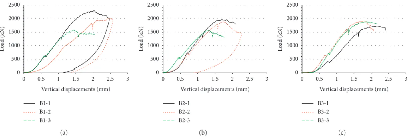
For B1 masonry panels, specimen 3 (B1-3) shows through the load-displacement relationship a reduction of strength by 26% than the mean value between B1-2 and B1-3. The in-dicators of the multileaf masonry panel B1-3 are out of the limit (Figure 6(a)), showing the intrinsic imperfections that affect the global behavior of the panel.
For the category B2, panel 3 (B2-3) shows a reduction of strength by 18% than the mean value between B2-2 and B2-3, confirming what was detected by the imperfection indicators (Figure 6(b)).
For the consolidated infill masonry panels (B3), all specimens show the intrinsic imperfections (Figure 6(c)); this result is confirmed by the similar load-displacement trend defined by all three specimens (Figure 7).
4.2.InitialConditions: Comparisonbetween Experimentaland Numerical Data. A comparison between experimental and
numerical data is reported by authors, with reference to the results provided in [18, 20]. The difficulty in modelling masonry is related to its composite nature, to the size of heterogeneity, to geometric complexities, and to the pres-ence of the infill. The literature regarding models and an-alyses of masonry structures is wide. Many different approaches may be found, among which the most common strategies adopted are the use of discrete [36–39] or con-tinuous models [40–45]. Moreover, in the case of multileaf walls, the presence of the fill, its thickness, the presence of voids and imperfections, the adherence between the leaves, etc. [23, 24] imply further difficulties regarding the evalu-ation of its structural behavior [30, 31].
In order to perform structural identification, continuous models have been adopted, with the purpose of comparing experimental and numerical dynamic parameters, such as modal shapes and frequencies. Finite-element models of the three different typologies of masonry specimens tested in the laboratory have been realized, using 3D brick elements and adopting the standard FE code. The structural identification allows defining the mechanical properties to adopt in modelling both the external masonry walls and the in-coherent material of the internal fill. Models reproduce the setup of the test: the base is fixed and the steel bar on top is
considered. The comparison between experimental and numerical results is of fundamental importance in order to calibrate the models and to evaluate their reliability in the description of the mechanical behavior of the specimens. Attention is limited at the beginning of the tests, step A, in order to evaluate the initial conditions.
It has been shown that the texture plays a crucial role in the behavior of multileaf masonry [46]; therefore, the mechanical properties of masonry external walls have been defined by means of a full 3D homogenization procedure [47]. Homogenization allows defining an equivalent orthotropic continuum able to reproduce at the macroscale the characteristics of masonry emerging at the microscale. At the microscale, a representative volume element (RVE), able to provide all the mechanical and geometrical characteristics needed to completely describe the whole panel, has been identified. The solution of the field problem, applying fully cinematic periodic boundary conditions on the RVE, makes it possible to derive the mechanical properties of the equivalent continuum to be used at the macroscale [40]. The mechanical properties of the material components used at microscale are the ones obtained by the mechanical characterization of constit-uent materials in the lab: 4000 MPa for bricks and 1150 MPa for mortar, as reported in Section 2.
In order to evaluate the reliability of the proposed ho-mogenization technique, a first comparison between the experimental test on compression described in Section 3 and a numerical linear static analysis has been performed [18]. Different load steps were applied in order to compare the displacements on top with the one measured in the lab, considering only the elastic phase—between the steps A and B defined in Figure 3(b)—where the load is basically carried only by the external walls [24]. Numerical results are in good agreement with the experimental ones: the mechanical properties obtained through the homogenization procedure for the external walls seem to be suitable. The mechanical properties adopted at the macroscale for the external wall are reported in Table 3.
A parametric natural frequencies analysis has been performed in order to identify the mechanical properties of the fill [20]. Attention has been focused initially on the
0 500 1000 1500 2000 2500 Lo ad (kN) 0.5 1 1.5 2 2.5 3 0 Vertical displacements (mm) B1-1 B1-2 B1-3 (a) 0 500 1000 1500 2000 2500 Lo ad (kN) 0.5 1 1.5 2 2.5 3 0 Vertical displacements (mm) B2-1 B2-2 B2-3 (b) 0 500 1000 1500 2000 2500 Lo ad (kN) 0.5 1 1.5 2 2.5 3 0 Vertical displacements (mm) B3-1 B3-2 B3-3 (c)
full infill typology B1. Being the central part completely filled up with brick potsherds and mortar, as shown in Figure 1, the infill has been considered as a continuum. The internal core has been therefore modelled as an isotropic continuum exhibiting reduced mechanical properties with respect to the external walls. Starting from the frequencies observed in the lab at the beginning of the test—step A—the solution of the inverse problem made possible the evaluation of the appropriate values of the mechanical properties to be adopted for the fill in the FE model. In particular, adopting the mechanical properties of the infill (E � 2756 MPa and ] � 0.4), the analysis pro-vides the 1st bending mode with a frequency of 6.3 Hz, in good agreement with the mean value of 6.4 Hz recorded experimentally for the 1st bending mode of B1 specimens. A further parametric analysis has been performed to define the properties of the fill in the case of damaged infill B2 and consolidated infill B3. However, as shown in [20], the adoption of a continuous model for the fill is not able to provide reliable results for damaged fill, where the multileaf walls lose their monolithicity and the two external walls behave differently, as shown by the uncoupled modes ex-perimentally recorded. To overcome this aspect, a model in which the two external walls are modelled as two separate leaves, taking into account the mass of the infill as a non-structural mass, has been proposed. Being the damaged filling realized only with brick potsherds (Figure 3), even the adoption of very low values of mechanical properties of the infill does not provide the decrease of frequencies compared with the experimental ones. Modelling the two external walls as separate leaves allows obtaining frequencies closer to the experimental ones, also in the case of consolidated infill. The two models adopted are reported in Figure 8.
The first six modes of vibration have been considered, and numerical results are in good agreement with experi-mental measures, as reported in Table 4.
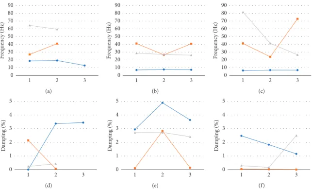
4.3. Steps B and C: Damage Identification. Figures 9–11
define the trends and compare the dynamic parameters with different damage conditions: undamaged, damaged to 35% of failure load, and damaged to 75% of failure load. In general, the frequency values increase dramatically from undamaged to damaged masonry panels, with a damage by 35% or 75%; the frequencies remain the same, while the damping ratios vary without following a law and are in-significant compared to a trend of structural response. The standard deviation (SD), calculated for every typology by the identified frequency values, listed in Tables 5–7, allows to
define the correspondence or the dispersion of values and then the local or global response of multileaf masonry walls. In detail, in every tables (Tables 5–7), the SD values of undamaged condition are subdivided into SD1 for all the values and SD2 distinguishing the first typology (full infill) from the second and third typologies (damaged and con-solidated infill).
For the first bending modal shape (Figure 9), the fre-quency values for every typology and for every damage condition are constant and within a narrow range. This modal shape involves globally the response of multileaf masonry walls.
The SD1 values reported in Table 5 highlight the greater scatter of all results for undamaged condition due to better homogeneity of full infill than damaged and consolidated infill. Distinguishing full infill from damaged and consolidated infill, the SD value changes from 1.89 (SD1) to 0.42 (SD2). For damaged conditions to 35% and 75% of failure load, the SD values are equal to 0.2 and 0.25, respectively, showing the uniformity between all specimens after the damage.
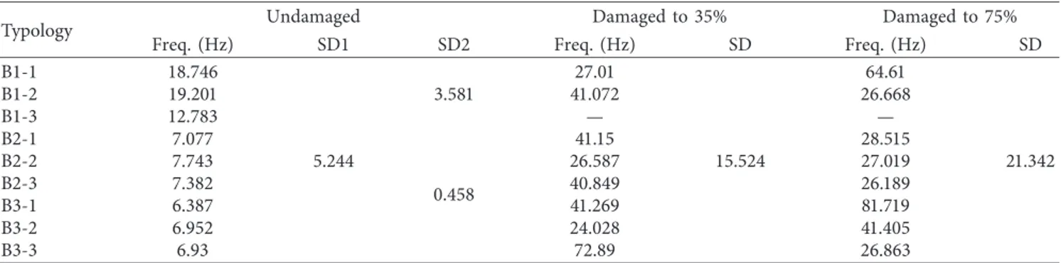
The torsional effects identified by the dynamic param-eters (Figure 10) show an incoherence between the three categories of multileaf masonry panels and between the specimens of the same typology. For this modal shape, the undamaged condition highlights a small variation between the frequencies of every specimen of the same category; for the damaged conditions, the variation of frequency values increases recording a wide range.
As shown in Table 6, the damaged conditions (35% and 75% of failure load) of the torsional modal shape show a greater dispersion of results (SD � 15.5 for 35% and SD � 21.3 for 75%) than the first bending modal shape (Table 5; SD � 0.2 for 35% and SD � 0.25 for 75%). The values of undamaged condition confirm the trend of the first modal shape.
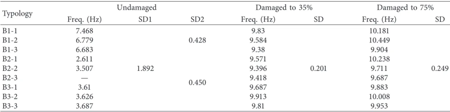
A coherence of results is shown in Figure 11 with the second flexural modal shapes. The frequencies with the flexural modal shapes respect the trend of the first modal shape. Excluding some precise exceptions, the frequency values are similar between the samples of each category.
In detail, for undamaged condition (Table 7), the vari-ation between the results confirms the distinction between the full infill and damaged-consolidated infill multileaf masonry panels (Figures 9 and 10; Tables 5 and 6). SD1 equal to 15.9 marks the variation of all values, while SD2 dis-tinguishes the two categories with 0.9 and 1.5 values.
For both damaged conditions to 35% and 75% of failure load, excluding few values, the ranges of frequency are narrow like the first bending modal shape. In detail, for damage to 35% and 75% of failure load, the SD values confirm the subdivision identified for the undamaged condition (see columns SD4 and SD5 of Table 7).
5. Final Remarks
Through the first results on damage/imperfection indicators based on vibration response, the following evaluations can be drawn:
Table 3: Mechanical properties adopted for external masonry walls. Young’s modulus (MPa) Shear modulus (MPa) Poisson’s coefficient E11�3450 G12�765 ]12�0.220 E22�3063 G23�782 ]23�0.248 E33�3560 G13�933 ]13�0.210
(i) The size of the three-leaf specimens does not affect the load-bearing capacity of three typologies that do not vary between full, damaged, and consoli-dated infill multileaf masonry panels.
(ii) The size of the three-leaf specimens, instead, affects the dynamic parameters of three typologies that do not vary between full, damaged, and consolidated infill multileaf masonry panels.
(iii) The procedure adopted based on damage/imperfec-tion identificadamage/imperfec-tion through different steps: in-vestigation, localization, description, estimation, and prediction, is reliable to analyze the complex systems characterized by multileaf masonry panels. (iv) The intrinsic imperfections can be evaluated through the comparison between the different indices: variation in modal frequencies and damping measurements to detect the degradation of structural characteristics (mass and stiffness), and variation in MAC indicators that localize and quantify the degree of correspondence between
two related mode shape vectors identifying the uncoupled and local modal shapes.
(v) The damping ratio is not reliable to investigate the imperfections and/or damage conditions.
(vi) Comparison with modal parameters allows de-fining numerical models able to describe the be-havior of multileaf masonry walls. In case of multileaf walls where damage or imperfection provokes a nonmonolithic behavior, continuous model is not completely suitable.
(vii) With respect to the main modal shapes, the tor-sional behavior amplifies with the damage the degree of the structural continuity between the different layers. The first and second bending modal shapes involve globally the masonry panels with out-of-plane mechanisms.
(viii) The increment trend of frequency values for every modal shape recorded with the increment of load and of crack patterns is due to the change in the structure of multileaf masonry walls through the closure of intrinsic gaps or cracks and the trigger of the interlock phe-nomena between the parts.
Starting from these remarks, it must be noticed that the geometric dimensions of the specimens strongly influence multileaf masonry behavior. In particular, it should be in-teresting to perform an experimental campaign that takes into account both bigger dimensions of the leaves and several thickness of the fill that play a fundamental role in the confinement effect.
(a) (b)
Figure 8: The adopted models for full infill B1 (a) and damaged infill (B2) and consolidated infill (B3) (b).
Table 4: Comparison between numerical and experimental frequencies.
Mode of
vibration B1 (Hz) FEM (Hz) B2 (Hz) B3 (Hz) FEM (Hz)
1st 6.4 6.3 3.1 3.6 3.4 2nd 16.9 14.4 7.4 6.7 6.9 3rd 21.3 16.5 18.3 14.8 12.0 4th 41.0 50.7 35.6 36.1 37.5 5th 58.1 65.4 41.7 43.2 43.4 6th 76.4 81.5 53.7 48.7 48.6
1 2 Undamaged Damaged 35% Damaged 75% 3 0 2 4 6 8 10 12 Fr eq uenc y (H z) (a) Undamaged Damaged 35% Damaged 75% 1 2 3 0 2 4 6 8 10 12 Fr eq uenc y (H z) (b) Undamaged Damaged 35% Damaged 75% 1 2 3 0 2 4 6 8 10 12 Fr eq uenc y (H z) (c) Undamaged Damaged 35% Damaged 75% 1 2 3 0 1 2 3 4 5 D am pin g (%) (d) Undamaged Damaged 35% Damaged 75% 1 2 3 0 1 2 3 4 5 D am pin g (%) (e) Undamaged Damaged 35% Damaged 75% 1 2 3 0 1 2 3 4 5 D am pin g (%) (f)
Figure9: 1st bending modal shape: comparison of dynamic parameters.
1 2 3 0 10 20 30 40 50 60 70 80 90 Fr eq uenc y (H z) (a) 1 2 3 0 10 20 30 40 50 60 70 80 90 Fr eq uenc y (H z) (b) 1 2 3 0 10 20 30 40 50 60 70 80 90 Fr eq uenc y (H z) (c) 1 2 3 0 1 2 3 4 5 D am pin g (%) (d) 1 2 3 0 1 2 3 4 5 D am pin g (%) (e) 1 2 3 0 1 2 3 4 5 D am pin g (%) (f)
Nonlinear static analysis will be carried out on the nu-merical model calibrated through the identified dynamic parameters to verify the correspondence between the
numerical and experimental structural response. Model updating will be proposed in order to describe evolution of damage. 1 2 3 0 10 20 30 40 50 60 70 80 90 Fr eq uenc y (H z) (a) 1 2 3 0 10 20 30 40 50 60 70 80 90 Fr eq uenc y (H z) (b) 1 2 3 0 10 20 30 40 50 60 70 80 90 Fr eq uenc y (H z) (c) 1 2 3 0 1 2 3 4 5 D am pin g (%) (d) 1 2 3 0 1 2 3 4 5 D am pin g (%) (e) 1 2 3 0 1 2 3 4 5 D am pin g (%) (f)
Figure11: 2nd bending modal shape: comparison of dynamic parameters.
Table5: Frequency values and standard deviation (SD) for the 1st bending modal shape.
Typology Undamaged Damaged to 35% Damaged to 75%
Freq. (Hz) SD1 SD2 Freq. (Hz) SD Freq. (Hz) SD
B1-1 7.468 1.892 0.428 9.83 0.201 10.181 0.249 B1-2 6.779 9.584 10.449 B1-3 6.683 9.38 9.904 B2-1 2.611 0.450 9.571 10.238 B2-2 3.507 9.396 9.711 B2-3 — 9.418 9.687 B3-1 3.61 9.687 9.883 B3-2 3.626 9.913 10.008 B3-3 3.687 9.81 9.953
Data Availability
The numerical and experimental dynamic data used to support the findings of this study are available from the corresponding author upon request.
Conflicts of Interest
The authors declare that they have no conflicts of interest.
Acknowledgments
The authors acknowledge the financial support of PRIN 2015 (under grant 2015JW9NJT_014, project “Advanced me-chanical modelling of new materials and structures for the solution of 2020 Horizon challenges”).
References
[1] C. R. Farrar and K. Worden, “An introduction to structural health monitoring,” Philosophical Transactions of the Royal
Society A: Mathematical, Physical and Engineering Sciences,
vol. 365, no. 1851, pp. 303–315, 2007.
[2] O. S. Salawu, “Detection of structural damage through changes in frequency: a review,” Engineering Structures, vol. 19, no. 9, pp. 718–723, 1997.
[3] S. W. Doebling, C. R. Farrar, and M. B. Prime, “A summary review of vibration-based damage identification methods,”
Shock and Vibration Digest, vol. 30, no. 2, pp. 91–105, 1998.
[4] L. F. Ramos, Damage identification on masonry structures
based on vibration signatures, Ph.D. thesis, Civil Engineering
Escola de Engenharia, Universidade do Minho, Braga, Por-tugal, 2007.
[5] C. Gentile and A. Saisi, “Ambient vibration testing of historic masonry towers for structural identification and damage assessment,” Construction and Building Materials, vol. 21, no. 6, pp. 1311–1321, 2007.
[6] U. Di Sabatino, V. Gattulli, M. Lepidi, and F. Potenza, “New insights in the modal identification of a monumental structure from long-term seismic structural monitoring,” in
Pro-ceedings of 6th International Operational Modal Analysis Conference, IOMAC, Guimarães, Portugal, May 2015.
[7] V. Gattulli, M. Lepidi, and F. Potenza, “Dynamic testing and health monitoring of historic and modern civil structures in Italy,” Structural Monitoring and Maintenance, vol. 3, no. 1, pp. 71–90, 2016.
[8] E. Durukal, S. Cimilli, and M. Erdik, “Dynamic response of two historical monuments in Istanbul deduced from the recordings of Kocaeli and D¨uzce Earthquakes,” Bulletin of the
Seismological Society of America, vol. 93, no. 2, pp. 694–712,
2003.
[9] K. Beyen, “Structural identification for post-earthquake safety analysis of the Fatih mosque after the 17 August 1999 Kocaeli earthquake,” Engineering Structures, vol. 30, no. 8, pp. 2165– 2184, 2008.
[10] L. Zanotti Fragonara, G. Boscato, R. Ceravolo et al., “Dynamic investigation on the Mirandola bell tower in post-earthquake scenarios,” Bulletin of Earthquake Engineering, vol. 15, no. 1, pp. 313–337, 2017.
[11] N. Cavalagli, G. Comanducci, C. Gentile, M. Guidobaldi, A. Saisi, and F. Ubertini, “Detecting earthquake-induced damage in historic masonry towers using continuously monitored dynamic response-only data,” Procedia
Engi-neering, vol. 199, pp. 3416–421, 2017.
[12] F. Ubertini, N. Cavalagli, A. Kita, and G. Comanducci, “Assessment of a monumental masonry bell-tower after 2016 Table 6: Frequency values and standard deviation (SD) for the 1st torsional modal shape.
Typology Undamaged Damaged to 35% Damaged to 75%
Freq. (Hz) SD1 SD2 Freq. (Hz) SD Freq. (Hz) SD
B1-1 18.746 5.244 3.581 27.01 15.524 64.61 21.342 B1-2 19.201 41.072 26.668 B1-3 12.783 — — B2-1 7.077 0.458 41.15 28.515 B2-2 7.743 26.587 27.019 B2-3 7.382 40.849 26.189 B3-1 6.387 41.269 81.719 B3-2 6.952 24.028 41.405 B3-3 6.93 72.89 26.863
Table 7: Frequency values and standard deviation (SD) for the 2nd bending modal shape.
Typology Undamaged Damaged to 35% Damaged to 75%
Freq. (Hz) SD1 SD2 Freq. (Hz) SD3 SD4 Freq. (Hz) SD5
B1-1 73.113 15.919 0.940 37.64 14.27 0.89 40.545 18.75 B1-2 74.728 38.902 40.124 B1-3 74.755 48.616 72.808 B2-1 42.97 1.504 66.247 6.22 72.858 0.015 B2-2 41.726 62.615 72.834 B2-3 40.444 72.915 72.876 B3-1 42.259 72.876 72.858 B3-2 44.99 58.872 72.862 B3-3 42.392 41.182 72.876
Central Italy seismic sequence by long-term SHM,” Bulletin of
Earthquake Engineering, vol. 16, no. 2, pp. 775–801, 2018.
[13] C. Gentile, A. Saisi, and A. Cabboi, “Structural identification of a masonry tower based on operational modal analysis,”
International Journal of Architectural Heritage, vol. 9, no. 2,
pp. 98–110, 2015.
[14] R. Ceravolo, G. Pistone, L. Zanotti Fragonara, S. Massetto, and G. Abbiati, “Vibration-based monitoring and diagnosis of cultural heritage: a methodological discussion in three ex-amples,” International Journal of Architectural Heritage, vol. 10, no. 4, pp. 375–395, 2016.
[15] L. A. S. Kouris, A. Penna, and G. Magenes, “Seismic damage diagnosis of a masonry building using short-term damping measurements,” Journal of Sound and Vibration, vol. 394, pp. 366–391, 2017.
[16] C. Oyarzo-Vera and N. Chouw, “Vibration based damage identification of an unreinforced masonry panel,” in
Pro-ceedings of the 5th International Operational Modal Analysis Conference (IOMAC’13), pp. 1–10, Guimaraes, Portugal, May
2013.
[17] C. Oyarzo-Vera and N. Chouw, “Damage identification of unreinforced masonry panels using vibration-based tech-niques,” Shock and Vibration, vol. 2017, Article ID 9161025, 14 pages, 2017.
[18] I. Aldreghetti, D. Baraldi, G. Boscato et al., “Multi-leaf ma-sonry walls with full, damaged and consolidated infill: ex-perimental and numerical analyses,” Key Engineering
Materials, vol. 747, pp. 488–495, 2017.
[19] I. Aldreghetti, D. Baraldi, G. Boscato et al., “Damage-imperfection indicators for the assessment of multi-leaf masonry walls under different conditions,” Edited by G. Milani, A. Taliercio, and S. Garrity, Eds., in Proceedings of
10th IMC-10th International Masonry Conference, pp. 9–11,
Milan, Italy, July 2018.
[20] G. Boscato, E. Reccia, and A. Cecchi, “Non-destructive ex-perimentation: dynamic identification of multi-leaf masonry walls damaged and consolidated,” Composites Part B:
Engi-neering, vol. 133, pp. 145–165, 2018.
[21] D. Baraldi, E. Reccia, and A. Cecchi, “Compressive and shear behaviour of masonry panels: experimentation and numerical analysis” in Proceedings of 10th IMC-10th International
Masonry Conference, G. Milani, A. Taliercio, and S. Garrity,
Eds., pp. 9–11, Milan, Italy, July 2018.
[22] L. Binda, G. Baronio, D. Penazzi, M. palma, and C. Tiraboschi, “Caratterizzazione di murature in pietra in zona sismica: data-base sulle sezioni murarie e indagini sui materiali,” in
Pro-ceedings of 9° Convegno nazionale “L’ingegneria sismica in
Italia”, Torino, Italy, 1999.
[23] A. Drei and A. Fontana, “Influence of geometrical and ma-terial properties on multiple-leaf walls behaviour,” in
Pro-ceedings of 7th International Conference, STREMAH, Bologna,
Italy, 2001.
[24] L. Binda, J. Pina-Henriques, A. Anzani, A. Fontana, and P. B. Lourenço, “A contribution for the understanding of load-transfer mechanisms in multi-leaf masonry walls: testing and modelling,” Engineering Structures, vol. 28, no. 8, pp. 1132–1148, 2006.
[25] M. Ramalho, A. Taliercio, A. Anzani, L. Binda, and E. Papa, “Experimental and numerical study of multi-leaf masonry walls,” WIT Transactions on the Built Environment, vol. 83, pp. 333–342, 2005.
[26] D. V. Oliveira, R. A. Silva, E. Garbin, and P. B. Lourenco, “Strengthening of three-leaf stone masonry walls: an
experimental research,” Materials and Structures, vol. 45, no. 8, pp. 1259–1276, 2012.
[27] E. Vintzileou, “Three-leaf masonry in compression, before and after grouting: a review of literature,” International
Journal of Architectural Heritage, vol. 5, no. 4-5, pp. 513–538,
2011.
[28] M. R. Valluzzi, F. Da Porto, and C. Modena, “Behavior and modeling of strengthened three-leaf stone masonry walls,”
Materials and Structures, vol. 37, no. 267, pp. 184–192, 2004.
[29] B. Silva, M. Dalla Benetta, F. Da Porto, and M. R. Valluzzi, “Compression and sonic tests to assess effectiveness of grout injection on three-leaf stone masonry walls,” International
Journal of Architectural Heritage, vol. 8, no. 3, pp. 408–435,
2004.
[30] M. Ramalho, E. Papa, A. Taliercio, and L. Binda, “A numerical model for multi-leaf stone masonry,” in Proceedings of 11th
International Conference on Fracture ICF11, pp. 3247–3252,
Turin, Italy, March 2005.
[31] G. Milani, “3D upper bound limit analysis of multi-leaf masonry walls,” International Journal of Mechanical
Sci-ences, vol. 50, no. 4, pp. 817–836, 2008.
[32] G. Milani, “3D FE limit analysis model for multi-layer ma-sonry structures reinforced with FRP strips,” International
Journal of Mechanical Sciences, vol. 52, no. 6, pp. 784–803,
2010.
[33] M. Giaretton, “Experimental study on the dynamic behaviour
of multi-leaf stone masonry walls reinforced through injections and transversal steel ties,” M.S. thesis, University of Padova,
Padova, Italy, 2011.
[34] P. Guillaume, H. Van der Auweraer, P. Verboven, S. Vanlanduit, and B. Peeters, “A poly-reference imple-mentation of the least-squares complex frequency domain-estimator,” in Proceedings of the 21th International Modal
Analysis Conference, Kissimmee, FL, USA, 2003.
[35] D. J. Ewins, Modal Testing, Research Studies Press Ltd., Boston, MA, USA, 2000.
[36] C. Baggio and P. Trovalusci, “Limit analysis for no-tension and frictional three-dimensional discrete systems,” Mechanics
of Structures and Machines, vol. 26, no. 3, pp. 287–304, 1998.
[37] A. Cecchi and K. Sab, “A comparison between a 3D discrete model and two homogenised plate models for periodic elastic brickwork,” International Journal of Solids and Structures, vol. 41, no. 9-10, pp. 2259–2276, 2004.
[38] J. V. Lemos, “Discrete element modeling of masonry struc-tures,” International Journal of Architectural Heritage, vol. 1, no. 2, pp. 190–213, 2007.
[39] D. Baraldi, E. Reccia, and A. Cecchi, “In plane loaded masonry walls: DEM and FEM/DEM models. A critical review,”
Meccanica, vol. 53, no. 7, pp. 1613–1628, 2018.
[40] A. Cecchi and K. Sab, “A multi-parameter homogenization study for modeling elastic masonry,” European Journal of
Mechanics, A/Solids, vol. 21, no. 2, pp. 249–268, 2002.
[41] A. Cecchi and R. Di Marco, “Homogenized strategy toward constitutive identification of masonry,” Journal of Engineering
Mechanics, vol. 128, no. 6, pp. 688–697, 2002.
[42] P. B. Lourenço, G. Milani, A. Tralli, and A. Zucchini, “Analysis of masonry structures: review of and recent trends in ho-mogenization techniques,” Canadian Journal of Civil
Engi-neering, vol. 34, no. 11, pp. 1443–1457, 2007.
[43] M. L. de Bellis and D. Addessi, “A Cosserat based multi-scale model for masonry structures,” International Journal for
Multiscale Computational Engineering, vol. 9, no. 5,
[44] C. Casalegno, A. Cecchi, E. Reccia, and S. Russo, “Hetero-geneous and continuous models: comparative analysis of masonry wall subjected to differential settlements,”
Com-posites: Mechanics, Computations, Applications: An In-ternational Journal, vol. 4, no. 3, pp. 187–207, 2013.
[45] D. Baraldi, A. Cecchi, and A. Tralli, “Continuous and discrete models for masonry like material: a critical comparative study,” European Journal of Mechanics, A/Solids, vol. 50, pp. 39–58, 2015.
[46] S. Casolo and G. Milani, “Simplified out-of-plane modeling of three-leaf masonry walls accounting for the material texture,”
Construction and Building Materials, vol. 40, pp. 330–351,
2013.
[47] E. Reccia, G. Milani, A. Cecchi, and A. Tralli, “Full 3D ho-mogenization approach to investigate the behavior of ma-sonry arch bridges: the Venice trans-lagoon railway bridge,”
Construction and Building Materials, vol. 66, pp. 567–586,
International Journal of
Aerospace
Engineering
Hindawi www.hindawi.com Volume 2018Robotics
Journal of Hindawi www.hindawi.com Volume 2018 Hindawi www.hindawi.com Volume 2018Active and Passive Electronic Components VLSI Design Hindawi www.hindawi.com Volume 2018 Hindawi www.hindawi.com Volume 2018
Shock and Vibration
Hindawi
www.hindawi.com Volume 2018
Civil Engineering
Advances inAcoustics and VibrationAdvances in
Hindawi
www.hindawi.com Volume 2018
Hindawi
www.hindawi.com Volume 2018
Electrical and Computer Engineering Journal of Advances in OptoElectronics Hindawi www.hindawi.com Volume 2018
Hindawi Publishing Corporation
http://www.hindawi.com Volume 2013 Hindawi www.hindawi.com
The Scientific
World Journal
Volume 2018 Control Science and Engineering Journal of Hindawi www.hindawi.com Volume 2018 Hindawi www.hindawi.com Journal ofEngineering
Volume 2018Sensors
Journal of Hindawi www.hindawi.com Volume 2018 Machinery Hindawi www.hindawi.com Volume 2018 Modelling & Simulation in Engineering Hindawi www.hindawi.com Volume 2018 Hindawi www.hindawi.com Volume 2018 Chemical EngineeringInternational Journal of Antennas and
Propagation International Journal of Hindawi www.hindawi.com Volume 2018 Hindawi www.hindawi.com Volume 2018 Navigation and Observation International Journal of Hindawi www.hindawi.com Volume 2018

![Table 3: Mechanical properties adopted for external masonry walls. Young’s modulus (MPa) Shear modulus (MPa) Poisson’s coefficient E 11 � 3450 G 12 � 765 ] 12 � 0.220 E 22 � 3063 G 23 � 782 ] 23 � 0.248 E 33 � 3560 G 13 � 933 ] 13 � 0.210](https://thumb-eu.123doks.com/thumbv2/123dokorg/5488603.62764/8.900.76.438.143.235/mechanical-properties-adopted-external-masonry-modulus-poisson-coefficient.webp)