ANIDIS 2017 PISTOIA
Numerical analysis of the medieval Civic Tower of L’Aquila to prevent
seismic pounding effects.
Marco Dessalvia, Maria Cristina Porcua, and Manuel Sabab
aDept. of Mechanical, Chemical and Materials Engineering, University of Cagliari, piazza D’Armi, 09123 Cagliari, Italy.
b
Investigation Group Environmental Modelling, Faculty of Engineering Universidad de Cartagena, Cra. 6 #36-100, Cartagena, Bolívar – Colombia.
Keywords: seismic behaviour, masonry historical buildings, seismic pounding, 3D dynamic model, L’Aquila earthquake.
ABSTRACT
The Civic Tower is one of the historical monuments damaged by the severe earthquake which struck the town of L’Aquila in 2009. Although it has been heavily modified during its long life, this masonry tower still represents one of the oldest monuments of L’Aquila. Presently, it forms a monumental complex with the adjacent lower building called “Palazzo Margherita”, the city hall of L’Aquila. The two structures are very close but separated to each other and exhibit a different seismic behaviour. This may trigger pounding effects during strong earthquakes. With the purpose of evaluating the extent of the pounding phenomenon, a three-dimensional model of the tower has been developed in the present paper. By referring to experimental data available in the literature, relevant to vibration-based tests made on the tower after the 2009 earthquake, the modal parameters of the numerical model have been identified. Different models of the tower were actually considered to assess the influence of some geometrical and material uncertainties. A code-based modal response spectrum analysis was carried out to determine the tower maximum displacements at the top level of the adjacent building. The distance that would accommodate the peak displacements of out-of phase oscillations under seimic design actions was thus calculated by taking also into account the peak displacements of “Palazzo Margherita”. Finally, the paper briefly examined some strategies to mitigate the pounding effects during future earthquakes.
1 INTRODUCTION
Masonry historical buildings may be strongly damaged by seismic events. Their vulnerability is due to several factors among which are age, structural alterations with respect to the original design, material degradation and lack of homogeneity (Arcos and Porcu, 2003). Historical buildings are widespread in countries like Italy, where the seismic retrofitting of the historical heritage is of particular importance. Typical constructions belonging to such heritage are the medieval towers which stand out in most Italian towns. Originally built for religious, defensive or municipal purposes, they are tall and slender structures that deserve particular care due to their high seismic vulnerability. Several studies on the behaviour of such structures under static and dynamic loads were made (Pavlovic et al. 2016),
(Marra et al. 2017), (Preciado et al. 2016), (Valente and Milani 2016).
Sometimes, medieval towers are adjacent to other lower buildings, from which they are however structurally separated. The different dynamic properties of adjacent buildings may cause out-of-phase oscillations and, as a consequence, impact between structures during earthquakes. This phenomenon, known as seismic pounding, may add to other sources of seismic damage and affect historical buildings (Decanini et al. 2004), (Pratesi et al. 2011) as well as modern structures (Jankowski 2009), (Pratesi et al. 2013).
The case of the Civic Tower of L’Aquila, which was severely damaged by the 2009 earthquake, is considered in the present paper. One of the likely causes of the tower damage was in fact the pounding phenomenon which occurred between the Civic Tower and “Palazzo
Margherita”, an ancient building very close to the tower. By means of a 3D finite element model, validated through the identification of some mechanical parameters, the seismic displacements involved in the pounding phenomenon are evaluated and some possible strategies to reduce the pounding-induced damage during future events are examined.
2 THE CIVIC TOWER OF L’AQUILA
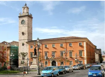
The Civic Tower of L’Aquila is a masonry tall and slender structure (from 6.77 m x 6.69 m at the base to 6,51 m x 6,21 on the top and 41 m in elevation) built in the thirteen century (about 1254) with an original height of 70 m. It is located next to the Margherita Palace, the city hall of the town. The picture in figure 1 shows the monumental complex before the 2009 earthquake. During its long life, the tower has undergone many modifications that also reduced its height to the actual one. A heavy bell is now located at the top of the tower (in place of the two original bells) and a public clock is still visible on its façade.
Figure 1. The Civic Tower of L’Aquila and the adjacent “Palazzo Margherita” before the 2009 earthquake.
A section of the lower part of the tower is provided in figure 2a , showing that the structure is hollow inside and it is divided into three floors evidenced by external cornices. The same figure also shows that the tower walls are faced with limestone squared blocks and filled with rubble masonry. Orthogonal walls have been recently connected by 15 steel ties, the anchor plates of which are visible in the façade (see figure 2b).The wall thickness narrows from 2.00 m at the base to 0.40 m at the top, as shown by figures 3a and 3b.
(a) (b)
Figure 2. (a) Tower vertical section; (b) anchor plates of the interior steel ties.
(a) (b)
Figure 3. (a) Civic Tower base plan and (b) vertical section.
Earthquakes of different violence stroke the tower during the eight centuries of its life. The degradation of the mechanical properties of the masonry walls, the structural slenderness and the presence of the adjacent building make the tower particularly vulnerable under seismic loads. In fact, a diffused crack pattern was detected along the tower shaft after the 2009 earthquake (Lorenzoni et al. 2012). It was particularly serious at the basement, as evidenced by figure 4.
(a) (b)
Figure 4. (a) Crack pattern at the basement; (b) main crack pattern reconstruction (Lorenzoni et al. 2012).
The crack pattern together with the rotation about the vertical axis, suffered by the tower during the 2009 earthquake, suggested to perform immediate bracing interventions and to implement a permanent health monitoring (see figure 5) while programming a definitive retrofitting of the tower (Lorenzoni et al. 2012).
Figure 5. Post-earthquake temporary metallic bracing.
3 NUMERICAL MODEL OF THE TOWER
Based on the data kindly shared by the city of L’Aquila (Comune di L’Aquila 2013), on some historical documents and on further data found in the literature (Lorenzoni et al. 2012), (Cimellaro et al. 2010), a detailed tower geometry has been drown by means of a commercial CAD software. Geometry was then imported in the ANSYS R13.0 software (ANSYS 2010) to perform a finite element analysis.
A three-dimensional model of the Civic Tower has been implemented with Ansys. The structure was assumed to be rigidly connected to the ground and no soil-structure interaction was considered in the analysis. The presence of the tie rods inside the tower was modelled by coupling the motion equations of the involved nodes. This allowed taking into account the improvement given to the box-like behaviour of the structure (stiffening effect). The presence of the three slabs was also accounted for in the numerical model.
The masonry walls were modelled through 3D 10-nodes tetrahedral structural solid elements (SOLID186, see figure 6a). A linear elastic analysis was developed by assuming a homogeneous isotropic behaviour for masonry.
For some research purposes, the non-linear dissipative behaviour of the masonry can sometimes be taken into account. For instance, (Cimellaro et al. 2010) assumed a non-linear
model for masonry to assess the cracking pattern of the Civic Tower of L’Aquila. However, to assess the extent of the pounding phenomenon, which is in fact the purpose of the present study, the hypothesis of a linear elastic behaviour of the masonry may be sufficient and, furthermore, even lead to more conservative results.
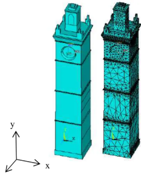
Figure 7a provides the geometrical shape and the mesh of the three-dimensional model. A total of 25681 SOLID186 elements were considered in the mesh. A wall width gradually narrowing along the tower height (from 2 m at the foundation to 0.40 m at the top) was assumed, also in agreement with what found in the literature, cf (Cimellaro et al. 2010).
(a) (b)
Figure 6. Ansys elements adopted in the model: (a) Solid186, 3D 10-nodes tetrahedral structural solid; (b) Combine14, 3D 2-nodes spring-damper.
Figure 7. Geometrical and FEM numerical model of the tower.
Although a large amount of data was available, some uncertainties still remained about the geometry of the structure and the properties of the wall masonry. On the other hand, the precarious conditions of the monument and the needs of preserving the historical heritage do not allowed internal inspections or destructive tests on the tower. Therefore, to assess the influence of geometrical and mechanical characteristics, several models of the tower were developed and checked during the present study. They differed in some geometrical features and/or inertial and elastic properties of masonry.
x z
A preliminary phase of identification of the mechanical and inertial properties of the tower masonry, based on the comparison between experimental and numerical frequencies, leaded eventually to select the models more suitable for the present study. For the sake of brevity, only the final results of the identification process will be herein discussed. In particular, two models, referred to as M_0 and M_S, are here considered. They differ from each other only in some springs that were introduced in model M_S, to account for the presence of the Margherita Palace. On the contrary, the M_0 model simulated the tower behaviour as it was an isolated structure (no added springs).
The values of the elastic moduli E and G and of the density
ρ
of the masonry, as adopted in both the above mentioned models, are provided in Table 1. It can be noted that two different values of the Young modulus were assigned to the lower part (low) and to the upper part (top) of the tower. The value of the elastic moduli in the lower part of the structure was reduced to account for a greater degradation of the mechanical properties, due to the more extensive crack pattern with respect to the upper part.The mechanical properties of the masonry walls of “Palazzo Margherita” are also provided in Table 1, as taken from (Comune di L’Aquila 2013). It is to note that the quality of the masonry of the palace walls is very poor (messy grain arrangement with clay inserts).
Table 1. Mechanical properties of masonry walls E (N/mm2) G (N/mm2) ρ (kN/m3) tower (low) 2200 846 24 tower (top) 2400 860 24 palace walls 725 241 19
Model M_S takes into account the presence of the adjacent “Palazzo Margherita” by means of some springs placed at the roof level of the palace (at a height of 15.22 m). Specifically, ten springs are added at each of the two sides where the palace is in contact with the tower (see figure 8). Although being a rather rough way to take into account the constraint given by the palace, this was however sufficient to improve the agreement between the first two experimental and numerical frequencies.
The element COMBIN14, schematized in figure 6b, was exploited to model the springs. A null damping coefficient was assumed in the
COMBIN14 element properties. One node of the element was fixed to the external world while the other one was made to coincide with a node of the tower (located at the same level of the palace roof).
The stiffness value of each spring was obtained by considering the total stiffness of the palace walls given by the following relation:
GA h EJ h K 2 . 1 12 1 3 + = (1)
where h is the wall height, E and G are the elastic moduli of the palace walls (see table 1), while A and J are the area and the moment of inertia of the section of the palace walls.
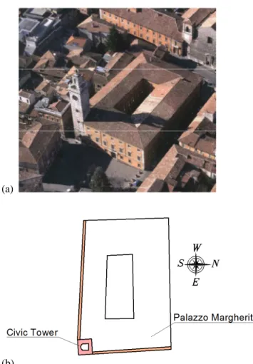
(a)
(b)
Figure 8. (a) Top view of the complex of the Civic Tower and the Margherita Palace; (b) schematic plan.
3.1 Modal analysis and frequency comparison
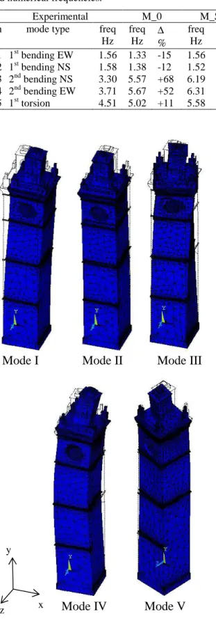
To identify the inertial and elastic properties of the numerical model, a modal analysis was carried out for each of the several models considered in the study. Similar mode shapes were found for all of them. The first five mode shapes are displayed in figure 9. The eigen
frequencies obtained for the numerical models M_0 and M_S are compared in Table 2 with the experimental values. The latter were obtained by (Lorenzoni et al. 2012) through post-earthquake ambient vibration tests. The percent discrepancy
∆
between numerical and experimental values is also provided in the same table.Table 2. Comparison between the first five experimental and numerical frequencies.
Experimental M_0 M_S
n mode type freq
Hz freq Hz ∆ % freq Hz ∆ % 1 1st bending EW 1.56 1.33 -15 1.56 0 2 1st bending NS 1.58 1.38 -12 1.52 -3.4 3 2nd bending NS 3.30 5.57 +68 6.19 +87 4 2nd bending EW 3.71 5.67 +52 6.31 +70 5 1st torsion 4.51 5.02 +11 5.58 +23
Mode I Mode II Mode III
Mode IV Mode V
Figure 9. First five mode shapes of the tower
It can be noted that the values of the first two fundamental frequencies (relevant to the first two bending orthogonal modes) are very close to each other both in the numerical model and in the experimental data. The same proximity of values can be observed also for the second bending mode in the two orthogonal directions. As also recalled in (Lorenzoni et al. 2012), this is a typical phenomenon of symmetric structures. However, by comparing experimental and numerical findings, it is evident that the torsional mode was found to be the fifth experimental mode, while it was the third numerical mode (see table 2 and figure 9).
Moreover, as far as the first two fundamental frequencies are concerned, model M_0 was found to be more flexible than the actual structure, see table 2. On the contrary, model M_S (which is stiffer due to the added springs) was found to be better able to catch the first two bending frequencies. The comparison provided in Table 2 shows that a less good agreement between experimental and numerical frequencies was found for both models when the higher frequencies are concerned.
It is to note, however, that the first bending modes actually give the main contribution to the lateral displacements, which are to be evaluated in the present study to assess the pounding effects.
4 PEAK DISPLACEMENTS FROM MODAL
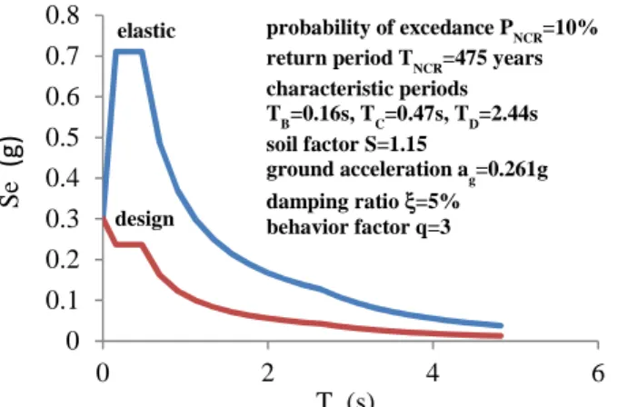
RESPONSE SPECTRUM ANALYSIS With reference to both the Italian Code (NTC 2008) and Eurocode 8 (CEN 2004), the elastic spectra given in figure 10 were obtained (the values of all the parameters defining the shape of the spectra are provided in the same figure). The spectra provided in figure 10 are relevant to the horizontal components of the earthquake, since the vertical component may be neglected in this case, according to both codes.
The design spectrum (obtained by reducing the elastic spectrum by the behaviour factor q) should be adopted to carry out the modal response spectrum analysis (MRSA). Moreover, according to Eurocode 8 (EC8), only the contribution of modes with effective modal mass greater than 5% of the total mass should be considered in the analysis, provided that the sum of the effective modal masses for the modes taken into account, amounts to at least 90% (85% as for Italian Code)
x z
of the total mass of the structure. The effective modal masses relevant to the first twenty modes of the M_S model are given in Table 3. Similar results were found for model M_0, but are not here reported for the sake of brevity.
Figure 10. Elastic and design response spectra for the no-collapse requirement (horizontal component) relevant to L’Aquila (LAT 13.394, LON 42.366).
As can be inferred from the last row of Table 3, the sum of the effective modal masses of the first twenty modes meets the requirement provided by the Italian code (at least 85% of the total mass) in the two horizontal directions. On the contrary, the contribution of other higher modes should be considered to meet the requirement of EC8 (at least 90%).
Table 3. Effective modal mass ratios
Mode x y z
1 0.439083 4.03E-07 1.75E-03
2 1.61E-03 1.44E-06 0.431432
3 3.03E-02 1.79E-06 2.09E-02
4 0.158928 5.39E-06 4.95E-02
5 2.72E-02 3.98E-05 0.145662
6 4.23E-06 0.5483 2.36E-03
7 3.81E-03 1.15E-02 9.40E-02
8 8.42E-02 5.91E-04 4.46E-03
9 2.77E-02 1.37E-05 6.14E-05
10 1.71E-02 1.46E-05 3.78E-02
11 2.08E-02 1.06E-05 3.16E-02
12 1.76E-04 1.70E-03 7.66E-06
13 8.56E-04 1.36E-06 1.33E-03
14 2.10E-05 1.44E-02 8.98E-07
15 6.32E-07 0.1333 3.22E-04
16 3.45E-03 3.55E-06 7.05E-07
17 3.66E-05 1.24E-02 1.24E-02
18 3.84E-02 2.31E-05 7.66E-05
19 2.21E-05 3.16E-03 2.80E-02
20 7.18E-04 3.36E-06 1.14E-04
sum 0.854 0.726 0.862
The peak displacements calculated both at the top of the tower and at the height of 15.22 m (roof level of the adjacent palace) are listed in table 4 for models M_0 and M_S. Figure 11
provides the peak displacement contour relevant to the model M_S, as obtained from the MRSA. Analogous results were obtained for the M_0 model, but are not here provided for brevity.
Table 4. Peak elastic displacements from the MRSA model M_0 model M_S top at 15.22 m top at 15.22 m x direction 3.75 1.04 3.29 0.75 z direction 3.64 1.00 3.14 0.68 (a) (b)
Figure 11. (a) Elastic displacements (in meters) along the x direction and (b) the y direction, as obtained from the MRSA (M_S model).
According to EC8, the displacement de of any point of the structural system, as obtained from the linear analysis, should be multiplied by the displacement behaviour factor qd so as to evaluate the displacement ds of the same point induced by the design seismic actions:
e d s q d d = (2) 0 0.1 0.2 0.3 0.4 0.5 0.6 0.7 0.8 0 2 4 6 T (s) S e (g ) probability of excedance PNCR=10% return period TNCR=475 years characteristic periods TB=0.16s, TC=0.47s, TD=2.44s soil factor S=1.15 ground acceleration ag=0.261g damping ratio ξ=5% behavior factor q=3 elastic design
wall of “Palazzo Margherita ” tower wall
In the present case the value of qd coincides with that of the behaviour factor q, that is qd =q=3. Table 5 gives the displacement values as obtained from eq. (2). These values should be taken into account to assess the pounding effects.
Table 5. Peak displacements as obtained from eq. (2) model M_0 model M_S top at 15.22 m top at 15.22 m x direction 11.25 3.13 9.87 2.25 z direction 10.92 3.00 9.42 2.04
5 STRATEGIES TO REDUCE POUNDING To evaluate how wide should be the separation between the Civic Tower and the adjacent building (“Palazzo Margherita”) to prevent collisions during their out-of-phase seismic oscillations, the peak displacements of both the structures at the roof level of the lower building (namely at 15.22 m) should be evaluated. Since the structure of “Palazzo Margherita” was not modelled in the present analysis, we referred to a previous study (Comune di L’Aquila 2013), where the peak seismic displacements at the top of that building were estimated through a MRSA. After applying eq. (2), we eventually obtained the peak displacements of the palace during the design earthquake, namely 2.8 cm in both x and y directions.
The minimum gap needed to avoid collision between the two considered buildings is the sum of the peak displacements of the tower and the palace at the level of 15.22 m. Conservatively, the values obtained from model M_0 can be exploited to this purpose. Therefore, a gap of about 6 cm in both directions (3.13 cm + 2.8 cm in the x direction and 3.00 cm + 2.8 cm in the y direction) should be considered to prevent pounding effects.
To stay on the safe side, this value could be also increases. It can be observed, in fact, that the minimum distance between buildings allowed by the Italian code [NTC] is:
g S Ha d g 5 = (3) Since in the present case ag = 0.261g, S=1.154 and H=15.22 m, the minimum distance d=9.2 cm was obtained. Therefore, a gap of 9÷10 cm could be conservatively considered in place of 6 cm.
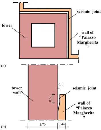
The first strategy to mitigate the seimic pounding effects can thus be that of designing a seismic joint between the tower and the adjacent building to accommodate their maximum relative displacements. To this purpose a gap (say of about 10 cm) between the two structures should be created, by realizing a notch along the contact line between the two structures (figure 12). The joint width may even narrow, as schematically showed in the figure, since the displacements of both structures reduce going down. Of course, the structural changes needed to insert the seismic joint should be carefully evaluated owing to the fact that they consist of destructive actions on the aged and poor-quality masonry walls of a historical monument.
(a)
(b)
Figure 12. Schematic (off-scale) representation of the seismic joint between tower and palace: (a) plan ; (b) section.
An alternative traditional mitigation strategy is that of strengthening both structures and in particular the tower, which is the more flexible between the two structures. A part from the practical aspects that this solution would involve (a complete retrofit of the structure may be usually required), it is also to stress that strengthening the tower’s structure could be even counterproductive. The reason resides in the fact that the fundamental vibration period of the tower is very high (near to 4s), which means low spectral accelerations (see figure 10) and
tower seismic joint wall of “Palazzo Margherita ” 1.70 0.44 seismic joint 0 .5 0 0.1
consequently low seismic actions. On the other hand, strengthening a structure usually also implies stiffening it. This in turn leads to lower its fundamental period and thus to increase the seismic loads on the system. For this reasons, the effects of a strengthening strategy on very flexible structures, such as the Civic Tower of L’Aquila, should be carefully evaluated when the goal is reducing their seismic response.
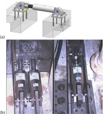
Another way to reduce seismic pounding could be that of linking the two structures by means of stiffening and dissipative devices. Among them we can cite the shock transmitters and the shape memory alloy devices. The shock transmitters are, in fact, velocity-dependent devices which are able to dissipate a great amount of the seismic energy (see figure 13a-b). Shape memory alloy devices, on the other hand, are able to recover very high deformations, owing to their thermo-mechanical properties. The use of such devices for seismic control in historical buildings is well documented (Bianco et al. 2008), (Martelli 2008), (Indirli and Castellano 2008). An emblematic instance of application of shock transmitters in a historical building is that relevant to the Basilica of San Francesco of Assisi, see figure 13b, (Martelli, 2007).
(a)
(b)
Figure 13. (a) Shock transmitter unity scheme; (b) shock transmitters inside the Basilica of San Francesco of Assisi.
Although a detailed analysis and the optimal sizing of such kind of devices in the present case-study is out of the purposes of this paper, two qualitative sketches of how the shock transmitters
can be disposed between the two considered adjacent buildings are given in figures 14a and 14b.
It is to note, finally, that the introduction of linking devices may induce stress concentrations, besides the fact that it may even strongly change the dynamic response of the connected structures. Moreover, it usually involves destructive actions on some parts of the historical structures. Therefore, a careful numerical evaluation of the consequences of this kind of mitigation strategy is always required (Indirli and Castellano 2008).
(a)
(b)
Figure 14. Possible positioning of shock transmitters between the tower and the palace: (a) in the façade; (b) inside the structures.
6 CONCLUSIONS
With reference to the Civic Tower of L’Aquila, the present study evidenced some of the difficulties that modelling historical buildings may typically involve. The complexity that the structural systems may inherently have (also due to the structural changes occurred during their life as well as to the age consequences and the effects of environmental actions) combined with the
palace wall tower wall 1.70 0.44 slab shock transmitter
needs of preservation, generally leads to inevitable uncertainties that have to be faced when studying the static or dynamic behavior of such systems.
When the results of experimental vibration tests on the real structure are available, these uncertainties may be also overcome by means of an identification procedure which usually takes a long time and a special care. This was the case of the present study. By exploiting the experimental mode shapes and frequency values available in the literature, the identification of some geometrical features, mechanical and inertial properties of the masonry walls as well as constraining effects produced on the tower by the presence of the adjacent palace, was finally made. A detailed 3D finite element model of the Civic Tower of L’Aquila was thus built with Ansis and it was exploited to evaluate the displacement demand of the tower under the design seismic actions.
Based on the modal response spectrum procedure given by EC8, a linear elastic analysis, made on the 3D FEM model, allowed to determine the peak displacements of the tower along the two orthogonal directions at the level where pounding may occur. When added to the peak displacements that the adjacent structure (Palazzo Margherita) may exhibit under the design earthquake, the latter allow to determine the minimum distance that the tower and the palace should have to prevent pounding phenomena.
This result could be exploited to design a seismic joint between the two buildings. Some other stratergies to mitigate the pounding effects are also briefly recalled in the paper. Of course, costs, seismic benefits and needs of preservation of the architectural and historical heritage should be considered when making the final choice.
AKNOWLEDGEMENTS
This project has been funded with support of the European Commission. This publication reflects the view only of the authors, and the Commission cannot be held responsible for any use which may be made of the information contained therein - Elarch Program (project reference number: 552129-em-1-2014-1-it-era mundus-ema21).
The authors are grateful to the city of L’Aquila for the data kindly provided.
REFERENCES
ANSYS, 2010. Release 13.0, User Manual. Canonsburg, PA, USA
Arcos, H., Porcu, M.C., 2003. Movimientos sísmicos y estructuras murarias. Consorcio de Compensación de
Seguros, 1-323.
Bianco, A., Candela, M., Fonti, R., 2008. Use of shock block transmitters in the structural rehabilitation of historical buildings in Calabria and Sicily. AIP
Conference Proceedings. July, 1020(1), 1320-1329.
CEN Eurocode 8, 2004. Design of Structures for
Earthquake Resistance - Part 1: General Rules, Seismic Actions and Rules for Buildings, European Comitee for
Standardization, Brussels.
Cimellaro, G.P., Salluzzo, G., Pianta, S., De Stefano, A., 2010. Nonlinear modeling of L’Aquila Civic Tower,
14th European Conference on Earthquake Engineering (14ECEE).
Comune di L’Aquila, 2013. Relazioni tecniche ed elaborati
grafici pubblicati nel bando del 25/05/2013, relativo alla ricostruzione del palazzo Margherita e Torre Civica e redati dai tecnici dell’assessorato alla ricostruzione dei beni culturali, Comune di L’Aquila. In
Italian.
Decanini, L., De Sortis, A., Goretti, A., Langenbach, R., Mollaioli, F., Rasulo, A., 2004. Performance of masonry buildings during the 2002 Molise, Italy, earthquake, Earthquake Spectra, 20(S1), S191-S220. Indirli, M., Castellano, M.G., 2008. Shape memory alloy
devices for the structural improvement of masonry heritage structures, International Journal of Architectural Heritage, 2(2), 93-119.
Jankowski, R., 2009. Non-linear FEM analysis of earthquake-induced pounding between the main building and the stairway tower of the Olive View Hospital, Engineering Structures, 31(8), 1851-1864. Lorenzoni, F., Aoki, T., Casarin, F., Modena, C., Da Porto,
F., Sabia, D., Sumini, V., 2012. Post-Earthquake assessment of the civic tower in L'Aquila: ambient vibration tests and structural health monitoring. SAHC
8th International Conference on Structural Analysis of Historical Constructions. October 15-October 17,
Wroclaw, Poland. 1, 1612-1620.
Marra, A. M., Salvatori, L., Spinelli, P., Bartoli, G., 2017. Incremental dynamic and nonlinear static analyses for
seismic assessment of medieval masonry
towers. Journal of Performance of Constructed Facilities, 31(4).
Martelli, A., 2007. Seismic isolation and energy dissipation: worldwide application and perspectives. Earthquake
Resistant Engineering Structures VI, 93-105.
Martelli, A., 2008. Recent progress of application of modern anti-seismic systems in Europe–Part 2: energy dissipation systems, shape memory alloy devices and shock transmitters. In The 14th world conference on
earthquake engineering, October, Beijing, China.
NTC 2008, Norme tecniche per il calcolo, l’esecuzione ed
il collaudo delle strutture in cemento armato, normale e precompresso e per le strutture metalliche. In Italian.
Pavlovic, M., Trevisani, S., Cecchi, A., 2016. Experimental and Numerical Analysis of a Historical Bell Tower. World Academy of Science, Engineering
and Technology, International Journal of Civil, Environmental, Structural, Construction and Architectural Engineering. 10(12), 1450-1457.
Pratesi, F., Sorace S., Terenzi G., 2013. Seismic pounding
mitigation of a modern heritage R/C bell tower. WIT
Transactions on The Built Environment, WIT press 131, 303-314.
Pratesi, F., Terenzi, G., Cozzi, M., Bandini, L., 2011. Il martellamento strutturale: metodo di analisi e strategia di adeguamento sismico della chiesa del Sacro Cuore di Firenze. Bollettino ingegneri, 8/9, 3-19.
Preciado, A., Sperbeck, S.T., & Ramírez-Gaytán, A., 2016. Seismic vulnerability enhancement of medieval and masonry bell towers externally prestressed with unbonded smart tendons. Engineering Structures, 122, 50-61.
Valente, M., Milani, G., 2016. Seismic assessment of historical masonry towers by means of simplified approaches and standard FEM. Construction and
Building Materials, 108, 74-104.
.