2017
Publication Year
2020-07-24T14:09:28Z
Acceptance in OA@INAF
An afocal telescope configuration for the ESA ARIEL mission
Title
Da Deppo, Vania; FOCARDI, MAURO; Middleton, Kevin; MORGANTE, GIANLUCA; Pascale, Enzo; et al.
Authors
10.1007/s12567-017-0175-3
DOI
http://hdl.handle.net/20.500.12386/26632
Handle
CEAS SPACE JOURNAL
Journal
9
Dear Author,
Here are the proofs of your article.
• You can submit your corrections online, via e-mail or by fax.
• For online submission please insert your corrections in the online correction form. Always indicate the line number to which the correction refers.
• You can also insert your corrections in the proof PDF and email the annotated PDF. • For fax submission, please ensure that your corrections are clearly legible. Use a fine black
pen and write the correction in the margin, not too close to the edge of the page.
• Remember to note the journal title, article number, and your name when sending your response via e-mail or fax.
• Check the metadata sheet to make sure that the header information, especially author names and the corresponding affiliations are correctly shown.
• Check the questions that may have arisen during copy editing and insert your answers/ corrections.
• Check that the text is complete and that all figures, tables and their legends are included. Also check the accuracy of special characters, equations, and electronic supplementary material if applicable. If necessary refer to the Edited manuscript.
• The publication of inaccurate data such as dosages and units can have serious consequences. Please take particular care that all such details are correct.
• Please do not make changes that involve only matters of style. We have generally introduced forms that follow the journal’s style.
Substantial changes in content, e.g., new results, corrected values, title and authorship are not allowed without the approval of the responsible editor. In such a case, please contact the Editorial Office and return his/her consent together with the proof.
• If we do not receive your corrections within 48 hours, we will send you a reminder. • Your article will be published Online First approximately one week after receipt of your
corrected proofs. This is the official first publication citable with the DOI. Further changes
are, therefore, not possible.
• The printed version will follow in a forthcoming issue.
Please note
After online publication, subscribers (personal/institutional) to this journal will have access to the complete article via the DOI using the URL: http://dx.doi.org/[DOI].
If you would like to know when your article has been published online, take advantage of our free alert service. For registration and further information go to: http://www.link.springer.com.
Due to the electronic nature of the procedure, the manuscript and the original figures will only be returned to you on special request. When you return your corrections, please inform us if you would like to have these documents returned.
Metadata of the article that will be visualized in
OnlineFirst
ArticleTitle An afocal telescope configuration for the ESA ARIEL mission Article Sub-Title
Article CopyRight CEAS
(This will be the copyright line in the final PDF)
Journal Name CEAS Space Journal
Corresponding Author Family Name Deppo
Particle Da
Given Name Vania
Suffix Division
Organization CNR-IFN Padova
Address Via Trasea 7, 35131, Padua, Italy
Division
Organization INAF-Osservatorio Astronomico di Padova Address Vicolo dell’Osservatorio 5, 35122, Padua, Italy
Phone 049-9815639
Fax
Email [email protected]
URL
ORCID http://orcid.org/0000-0001-6273-8738
Author Family Name Focardi
Particle
Given Name Mauro
Suffix Division
Organization INAF-Osservatorio Astrofisico di Arcetri Address Largo E. Fermi 5, 50125, Florence, Italy Phone
Fax Email URL ORCID
Author Family Name Middleton
Particle
Given Name Kevin
Suffix Division
Organization RAL Space-STFC Rutherford Appleton Laboratory
Address Harwell Campus, Didcot, OX11 0QX, UK
Fax Email URL ORCID
Author Family Name Morgante
Particle
Given Name Gianluca
Suffix Division
Organization INAF-IASF Bologna
Address Area della Ricerca, Via Piero Gobetti 101, 40129, Bologna, Italy Phone
Fax Email URL ORCID
Author Family Name Pascale
Particle
Given Name Enzo
Suffix Division
Organization Dip. di Fisica-Università degli Studi di Roma “La Sapienza”
Address Piazzale Aldo Moro 2, 00185, Rome, Italy
Division School of Physics and Astronomy
Organization Cardiff University
Address 5 The Parade, Cardiff, NSW, CF24 3AA, UK
Phone Fax Email URL ORCID
Author Family Name Grella
Particle
Given Name Samuele
Suffix Division
Organization Leonardo S.p.A
Address Via delle Officine Galileo 1, 50013, Florence, Campi Bisenzio, Italy Phone
Fax Email URL ORCID
Author Family Name Pace
Given Name Emanuele
Suffix Division
Organization Dip. di Fisica ed Astronomia-Università degli Studi di Firenze Address Largo E. Fermi 2, 50125, Florence, Italy
Phone Fax Email URL ORCID
Author Family Name Claudi
Particle
Given Name Riccardo
Suffix Division
Organization INAF-Osservatorio Astronomico di Padova Address Vicolo dell’Osservatorio 5, 35122, Padua, Italy Phone
Fax Email URL ORCID
Author Family Name Amiaux
Particle
Given Name Jerome
Suffix
Division Laboratoire Léon Brillouin
Organization UMR12, CEA-CNRS
Address 91191, Saclay, Gif sur Yvette, France
Phone Fax Email URL ORCID
Author Family Name Ferrer
Particle
Given Name Josep Colomé
Suffix Division
Organization Institut de Ciències de l’Espai, (CSIC-IEEC) Address Campus UAB, 08193, Bellaterra, Barcelona, Spain Phone
Fax Email URL
ORCID
Author Family Name Hunt
Particle
Given Name Thomas
Suffix
Division Mullard Space Science Laboratory
Organization Holmbury St. Mary
Address Dorking, Surrey, RH5 6NT, UK
Phone Fax Email URL ORCID
Author Family Name Rataj
Particle
Given Name Miroslaw
Suffix
Division Space Research Centre
Organization Polish Academy of Sciences
Address Bartycka 18A, 00-716, Warsaw, Poland
Phone Fax Email URL ORCID
Author Family Name Sierra-Roig
Particle
Given Name Carles
Suffix Division
Organization Institut de Ciències de l’Espai, (CSIC-IEEC) Address Campus UAB, 08193, Bellaterra, Barcelona, Spain Phone
Fax Email URL ORCID
Author Family Name Veltroni
Particle
Given Name Iacopo Ficai
Suffix Division
Organization Leonardo S.p.A
Address Via delle Officine Galileo 1, 50013, Florence, Campi Bisenzio, Italy Phone
Fax Email URL ORCID
Author Family Name Eccleston
Particle
Given Name Paul
Suffix Division
Organization RAL Space-STFC Rutherford Appleton Laboratory
Address Harwell Campus, Didcot, OX11 0QX, UK
Phone Fax Email URL ORCID
Author Family Name Micela
Particle
Given Name Giuseppina
Suffix Division
Organization INAF-Osservatorio Astronomico di Palermo Address Piazza del Parlamento 1, 90134, Palermo, Italy Phone
Fax Email URL ORCID
Author Family Name Tinetti
Particle
Given Name Giovanna
Suffix
Division Department of Physics and Astronomy
Organization University College London
Address Gower Street, London, WC1E 6BT, UK
Phone Fax Email URL ORCID Schedule Received 29 May 2017 Revised 26 September 2017 Accepted 6 October 2017
Abstract Atmospheric Remote-Sensing Infrared Exoplanet Large Survey (ARIEL) is a candidate as an M4 ESA mission to launch in 2026. During its 3.5 years of scientific operations, ARIEL will observe
spectroscopically in the infrared (IR) a large population of known transiting planets in the neighbourhood of the solar system. ARIEL aims to give a breakthrough in the observation of exoplanet atmospheres and understanding of the physics and chemistry of these far-away worlds. ARIEL is based on a 1 m class telescope feeding a collimated beam into two separate instrument modules: a spectrometer module covering the waveband between 1.95 and 7.8 μm and a combined fine guidance system/visible photometer/NIR spectrometer. The telescope configuration is a classic Cassegrain layout used with an eccentric pupil and coupled to a tertiary off-axis paraboloidal mirror. To constrain the thermo-mechanically induced optical aberrations, the primary mirror (M1) temperature will be monitored and finely tuned using an active thermal control system based on thermistors and heaters. They will be switched on and off to maintain the M1 temperature within ± 1 K by the telescope control unit (TCU). The TCU is a payload electronics subsystem also responsible for the thermal control of the spectrometer module detectors as well as the secondary mirror mechanism and IR calibration source management. The TCU, being a slave subsystem of the instrument control unit, will collect the housekeeping data from the monitored subsystems and will forward them to the master unit. The latter will run the application software, devoted to the main spectrometer management and to the scientific data on-board processing. Keywords (separated by '-') Space instrumentation - Telescope - Optical design - Exoplanetary science - Active thermal control - ICU Footnote Information This paper is based on a presentation at the International Conference on Space Optics (ICSO), 18–21
UN
C
ORRECTED PR
OOF
Journal : Large 12567 Article No : 175 Pages : 20 MS Code : CEAS-D-17-00051 Dispatch : 26-10-2017
Vol.:(0123456789)
1 3
CEAS Space J
DOI 10.1007/s12567-017-0175-3 ORIGINAL PAPER
An afocal telescope coniguration for the ESA ARIEL mission
Vania Da Deppo1,2 · Mauro Focardi3 · Kevin Middleton4 · Gianluca Morgante5 · Enzo Pascale6,7 ·
Samuele Grella8 · Emanuele Pace9 · Riccardo Claudi2 · Jerome Amiaux10 · Josep Colomé Ferrer11 · Thomas Hunt12 · Miroslaw Rataj13 · Carles Sierra-Roig11 · Iacopo Ficai Veltroni8 · Paul Eccleston4 · Giuseppina Micela14 ·
Giovanna Tinetti15
Received: 29 May 2017 / Revised: 26 September 2017 / Accepted: 6 October 2017 © CEAS 2017
telescope coniguration is a classic Cassegrain layout used with an eccentric pupil and coupled to a tertiary of-axis paraboloidal mirror. To constrain the thermo-mechanically induced optical aberrations, the primary mirror (M1) tem-perature will be monitored and inely tuned using an active thermal control system based on thermistors and heaters. They will be switched on and of to maintain the M1 tem-perature within ± 1 K by the telescope control unit (TCU). The TCU is a payload electronics subsystem also responsible for the thermal control of the spectrometer module detectors as well as the secondary mirror mechanism and IR calibra-tion source management. The TCU, being a slave subsystem of the instrument control unit, will collect the housekeep-ing data from the monitored subsystems and will forward them to the master unit. The latter will run the application
Abstract Atmospheric Remote-Sensing Infrared
Exo-planet Large Survey (ARIEL) is a candidate as an M4 ESA mission to launch in 2026. During its 3.5 years of scien-tiic operations, ARIEL will observe spectroscopically in the infrared (IR) a large population of known transiting planets in the neighbourhood of the solar system. ARIEL aims to give a breakthrough in the observation of exoplanet atmospheres and understanding of the physics and chem-istry of these far-away worlds. ARIEL is based on a 1 m class telescope feeding a collimated beam into two separate instrument modules: a spectrometer module covering the waveband between 1.95 and 7.8 μm and a combined ine guidance system/visible photometer/NIR spectrometer. The
This paper is based on a presentation at the International Conference on Space Optics (ICSO), 18–21 October, 2016, Biarritz, France.
* Vania Da Deppo [email protected]
1
CNR-IFN Padova, Via Trasea 7, 35131 Padua, Italy
2 INAF-Osservatorio Astronomico di Padova, Vicolo
dell’Osservatorio 5, 35122 Padua, Italy
3
INAF-Osservatorio Astroisico di Arcetri, Largo E. Fermi 5, 50125 Florence, Italy
4 RAL Space-STFC Rutherford Appleton Laboratory, Harwell
Campus, Didcot OX11 0QX, UK
5
INAF-IASF Bologna, Area della Ricerca, Via Piero Gobetti 101, 40129 Bologna, Italy
6 Dip. di Fisica-Università degli Studi di Roma “La Sapienza”,
Piazzale Aldo Moro 2, 00185 Rome, Italy
7
School of Physics and Astronomy, Cardif University, 5 The Parade, Cardif, NSW CF24 3AA, UK
8 Leonardo S.p.A, Via delle Oicine Galileo 1,
50013 Florence, Campi Bisenzio, Italy
9
Dip. di Fisica ed Astronomia-Università degli Studi di Firenze, Largo E. Fermi 2, 50125 Florence, Italy
10 Laboratoire Léon Brillouin, UMR12, CEA-CNRS,
91191 Saclay, Gif sur Yvette, France
11
Institut de Ciències de l’Espai, (CSIC-IEEC), Campus UAB, 08193 Bellaterra, Barcelona, Spain
12 Mullard Space Science Laboratory, Holmbury St. Mary,
Dorking, Surrey RH5 6NT, UK
13
Space Research Centre, Polish Academy of Sciences, Bartycka 18A, 00-716 Warsaw, Poland
14 INAF-Osservatorio Astronomico di Palermo, Piazza del
Parlamento 1, 90134 Palermo, Italy
15 Department of Physics and Astronomy, University College
London, Gower Street, London WC1E 6BT, UK
AQ1 AQ2 AQ3 1 2 3 4 5 6 7 8 9 10 11 12 13 14 15 16 17 18 19 20 21 22 23 24 25 26 27 28 29 30 31 32 33 34 35 36 A1 A2 A3 A4 A5 A6 A7 A8 A9 A10 A11 A12 A13 A14 A15 A16 A17 A18 A19 A20 A21 A22 A23 A24 A25 A26 A27 A28 A29 A30 A31 A32 A33 A34
Author Proof
UN
C
ORRECTED PR
OOF
Journal : Large 12567 Article No : 175 Pages : 20 MS Code : CEAS-D-17-00051 Dispatch : 26-10-2017
V. Da Deppo et al.
1 3
software, devoted to the main spectrometer management and to the scientiic data on-board processing.
Keywords Space instrumentation · Telescope · Optical
design · Exoplanetary science · Active thermal control · ICU
1 Introduction
ARIEL is one of the M4 proposed missions in the framework of the ESA Cosmic Vision program [1]. The ARIEL mission will address the fundamental questions on what exoplanets are made of and how planetary systems form and evolve by investigating the atmospheres of many hundreds of diverse known exoplanets orbiting diferent types of nearby stars [2].
About three thousand exoplanets have now been discov-ered; Gaia [3], Kepler [4], and K2 [5], together with other current ground and space-based surveys, will continue to increase the known exoplanet list. However, at present, very little is known about the nature of these exoplanets. Dur-ing its 3.5-year scientiic mission lifetime in L2 orbit, the ARIEL mission aims to measure the atmospheric composi-tion and structure of a large and well-deined selected sam-ple of exoplanets (∼ 1000). It will use transit spectroscopy in the 1.25–7.8 μm spectral range and multiple narrow-band photometry in the optical.
For its ambitious scientiic program, ARIEL is designed as a dedicated survey mission for transit and eclipse spec-troscopy, whereby the signal from the star and planet is dif-ferentiated using knowledge of the planetary ephemerides, transit, and eclipse and phase-curve spectroscopy methods allow to measure atmospheric signals from the planet at levels of 10–100 part per million (ppm) relative to the star and, given the bright nature of the targets, also allow more sophisticated techniques, such as eclipse mapping, to give a deeper insight into the nature of the atmosphere.
This mission will allow the exploration and sounding of the nature of the exoplanet atmospheres, to collect informa-tion about the planet interiors and to study the key factors afecting the formation and evolution of planetary systems [6].
Some simulations of the ARIEL performance in con-ducting exoplanet surveys have been performed. For this purpose, three elements have been taken into account: a con-servative estimate of the mission performance, a full model of all the possible signiicant noise sources present in the measurements, and a list of the potential ARIEL targets that incorporate the latest available exoplanet statistics. The conclusion is that ARIEL will be able to observe 500–1000 exoplanets, depending on the details of the adopted survey strategy, and the feasibility of the main science objectives is conirmed.
ARIEL will be highly complementary to other interna-tional facilities (such as TESS [7], to be launched in 2018) and will beneit from other ESA exoplanet missions such as CHEOPS [8] and PLATO [9], which will help to provide an optimized target list prior to launch.
At the beginning of this paper, the ARIEL mission sci-ence objectives and requirements will be presented (Sect. 2). Then, the description of the spacecraft and the science pay-load will follow (Sect. 3). After that, the discussion of the requirements and the design of the telescope will be given (Sect. 4). The solution adopted for cooling the payload and the results of the thermal analysis will be presented in Sect. 5; while the design details of the electronic units (ICU and TCU) controlling the instrument will be analysed in the last part (Sect. 6).
2 The ARIEL mission science
2.1 ARIEL observation strategy and science requirements
Depending on their mass, the exoplanets have been so far divided into three categories: rocky/icy planets (< 5 MEarth), gas rich planets (> 15 MEarth), and transitional planets (5–15
MEarth). The ARIEL selected exoplanet target sample will ensure to observe a statistically signiicant population for each of these three classes.
Diferent observation techniques will be used to gain information on diferent parts of the exoplanet atmospheres. Terminator regions will be studied with transit spectroscopy, day-side hemisphere via planetary eclipse spectroscopy and unilluminated night-side hemisphere using phase variation. In addition, the eclipse mapping method can be used to spatially resolve the day-side hemisphere and the repeated observation of a number of key planets in both transit and eclipse mode (i.e., time series of narrow spectral bands) will allow the monitoring of global meteorological variations and to probe cloud distribution and patchiness [6].
The ARIEL observation strategy is divided into three tiers. The irst one is a “reconnaissance survey” during which the selected 1000 exoplanet sample will be observed with low spectral resolution and SNR. This will allow to classify the exoplanet atmospheres and select the good candidates for further studies. The second phase is a “deep survey”, i.e., high spectral resolution observation in the Vis–IR of an exoplanet sub-sample, to determine the atmospheric com-ponents, chemical abundances, and thermal structure. The last tier is “benchmark planets”; the very best planets, which means those very interesting from a scientiic point of view, will be re-observed multiple times with all the techniques for a detailed knowledge of the planetary chemistry and dynam-ics, weather, and spatial and temporal variabilities.
37 38 39 40 41 42 43 44 45 46 47 48 49 50 51 52 53 54 55 56 57 58 59 60 61 62 63 64 65 66 67 68 69 70 71 72 73 74 75 76 77 78 79 80 81 82 83 84 85 86 87 88 89 90 91 92 93 94 95 96 97 98 99 100 101 102 103 104 105 106 107 108 109 110 111 112 113 114 115 116 117 118 119 120 121 122 123 124 125 126 127 128 129 130 131 132 133 134
Author Proof
UN
C
ORRECTED PR
OOF
Journal : Large 12567 Article No : 175 Pages : 20 MS Code : CEAS-D-17-00051 Dispatch : 26-10-2017
An afocal telescope coniguration for the ESA ARIEL mission
1 3
The key science performance parameters that will drive the speciication of the ARIEL mission have been identiied by the Science Study Team (SST) [10]. These requirements have been derived starting from the science objective, and they include the wavelength coverage, spectral resolving power, signal-to-noise ratio and noise requirements, photo-metric stability, sky visibility/source accessibility, temporal resolution, limiting targets, calibration, and zodiacal light and background. Starting from the science requirements, the SST has then derived the mission requirements [11].
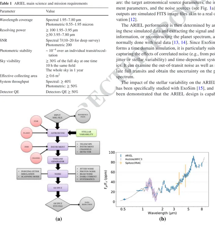
In Table 1, the most important science and mission requirements for the spectral and photometric observations are reported. The telescope requirements will be discussed in Sect. 4.1.
2.2 ARIEL performance requirements
A numerical end-to-end simulator of transit spectroscopy, called ExoSim, has been used to predict the ARIEL perfor-mance. It permits to simulate observations in the diferent observing modes, i.e., both primary transit and planetary eclipse (occultation) as well as phase curves. ExoSim inputs are: the target astronomical source parameters, the instru-ment parameters, and the noise sources (see Fig. 1a). The outputs are simulated FITS image iles akin to a real obser-vation [12].
The ARIEL performance is then determined by analys-ing these simulated data and extractanalys-ing the signal and noise information, or reconstructing the planet spectrum, as it is normally done with real data [13, 14]. Since ExoSim per-forms a time domain simulation, it is particularly suited for capturing the efects of correlated noise (e.g., from pointing jitter or stellar variability) and time-dependent systemat-ics. It can examine the out-of-transit noise as well as simu-late full transits and obtain the uncertainty on the planet spectrum.
The impact of the stellar variability on the ARIEL data has been speciically studied with ExoSim [15], and it has been demonstrated that the ARIEL design is capable of
Table 1 ARIEL main science and mission requirements
Parameter Value
Wavelength coverage Spectral 1.95–7.80 µm Photometric 0.55–1.95 micron Resolving power ≥ 100 1.95–3.95 µm
≥30 3.95–7.80 µm
SNR Spectral 7/(10–20 for deep survey) Photometric 200
Photometric stability ~ 10−4 over an individual
transit/occul-tation
Sky visibility ≥ 30% of the full sky at one time 10 h the same ield
The whole sky in 1 year Efective collecting area ≥ 0.6 m2
System throughput Spectral: ≥ 40% Photometric: ≥ 50% Detector QE Detectors QE ≥ 50%
Fig. 1 In a, ExoSim model architecture. In b, expected output from the ARIEL processed data [6]
135 136 137 138 139 140 141 142 143 144 145 146 147 148 149 150 151 152 153 154 155 156 157 158 159 160 161 162 163 164 165 166 167 168 169 170 171
Author Proof
UN
C
ORRECTED PR
OOF
Journal : Large 12567 Article No : 175 Pages : 20 MS Code : CEAS-D-17-00051 Dispatch : 26-10-2017
V. Da Deppo et al.
1 3
achieving a very high level of photometric stability to record the exoplanet atmospheric signal, i.e., 10–50 ppm relative to the target star (post-processing). Moreover, the broad instan-taneous wavelength range covered by ARIEL will allow to detect many molecular species, probe the thermal structure, identify/characterize clouds, and monitor/correct the stellar activity. To reach these goals, also requires a speciically designed stable payload and satellite platform.
An example of the expected output from the ARIEL pro-cessed data is shown in Fig. 1b. The simulated target is a hot super-Earth exoplanet orbiting around a G-type star. Data from eight simulated eclipses, i.e., about 32 h of observation, have been used. The results, with error bars, are compared to those obtainable with two current available facilities, i.e., Spitzer and Hubble WFC3.
The detailed ExoSim performance studies also show that an efective telescope collecting area of 0.6 m2, coupled to the required system throughput and detector QE, is suicient to achieve the necessary observations on all the ARIEL tar-gets within the mission lifetime.
ARIEL will carry a telescope unit feeding a collimated beam into two separate modules. A combined Fine Guid-ance System (FGS)/Vis Photometer/NIR Spectrometer that contains three photometric channels in the wavelength range between 0.50 and 1.20 μm to monitor the photometric sta-bility of the target stars. Two of these channels will also be used as a prime/redundant system for providing guidance and closed-loop control to the high stability pointing Atti-tude and Orbit Control System (AOCS) of the spacecraft (S/C). Integrated in this same module is a further low-reso-lution (R = ~ 10) spectrometer channel in the 1.20–1.95 μm waveband. This first combined module is often simply referred to as the FGS. The second module, acting as the main instrument, is the ARIEL IR Spectrometer (AIRS), providing variable resolving power in the range 30–180 for a waveband between 1.95 and 7.8 μm.
The payload is passively cooled to ~ 50 K by isolation from the S/C bus via a series of V-groove radiators. The AIRS detectors are the only items that require active cooling to < 42 K via an Ne JT cooler. While the other detectors, i.e., those for the FGS channels, will be actively stabilized at a temperature < 70 K by switching on/of their thermal control system (basically a heater).
3 Spacecraft and science payload
3.1 Spacecraft architecture
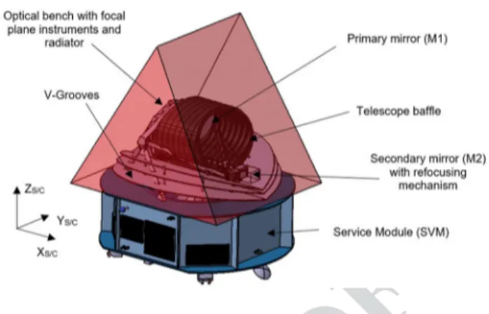
A “horizontal” coniguration, with respect to the Service Module (SVM) cylinder, has been adopted as baseline for the S/C architecture (see Fig. 2). The X-axis of the ARIEL mechanical reference system corresponds with the telescope
mirrors optical axis, the Z-axis is the launch vehicle symme-try axis (“vertical”), and Y-axis completes the right-handed set.
The S/C can be considered as composed of a cold Payload Module (PLM), containing the telescope and the instruments with their thermo-mechanical hardware, and a warm Ser-vice Module (SVM) that includes all the mission-supporting systems together with the PLM and cryogenic control units [16]. The PLM will interface to the SVM via a set of ther-mally isolating support struts, or bipods, and will be radia-tively shielded from the SVM and the solar input loads by a set of 3 V-Grooves (VGs).
The sun is located below the platform (i.e., − ZS/C). The V-grooves (see par. 3.1.3) and volumes are designed to accommodate a ± 6° angle and a ± 30° angle clearance, respectively, around the X-axis and the Y-axis with respect to the Sun vector. This solution has been taken to limit the size and mass of the VGs, which are needed to maintain the pay-load stable at cryogenic temperatures, and at the same time satisfying the requirements on the sky visibility. Assuming a representative operational orbit of ARIEL around L2, the complete sky is accessible within a year with any point on the sky observable for at least 4 months, and for the celestial poles, the coverage is continuous.
In Fig. 3, the sky visibility is shown. It has been indicated in fraction of a year for which a given location in the sky, expressed in equatorial coordinates, is visible. The superim-posed green and red circles are the currently known best tar-gets in terms of stellar brightness and planetary parameters (green circles are the very best), and yellow dots are known transiting planets observable by ARIEL. These current 200 known targets have been discovered mainly close to the ecliptic plane, because they are provided by ground-based surveys. K2, CHEOPS, and NGTS are expected to complete the search for planets around bright sources closer to the ecliptic plane. TESS and PLATO will extend the planet search closer to the ecliptic poles.
Fig. 2 Schematics of ARIEL S/C baseline coniguration: main
components and S/C reference system are highlighted; the red cover shows the minimum allowable volume with respect to the Sun vector 172 173 174 175 176 177 178 179 180 181 182 183 184 185 186 187 188 189 190 191 192 193 194 195 196 197 198 199 200 201 202 203 204 205 206 207 208 209 210 211 212 213 214 215 216 217 218 219 220 221 222 223 224 225 226 227 228 229 230 231 232 233 234 235 236 237 238 239 240 241 242 243 244 245 246 247 248 249 250 251 252 253 254 255 256 257
Author Proof
UN
C
ORRECTED PR
OOF
Journal : Large 12567 Article No : 175 Pages : 20 MS Code : CEAS-D-17-00051 Dispatch : 26-10-2017
An afocal telescope coniguration for the ESA ARIEL mission
1 3
3.1.1 Cold payload module architecture
To achieve its primary objectives, the mission carries a single dedicated payload that will be developed and deliv-ered by the ARIEL Payload Consortium [17]. A block dia-gram of the overall payload architecture with its subsys-tems is shown in Fig. 4. The ARIEL cold PLM consists of an integrated suite of telescope, spectrometers, and FGS/ photometers along with the necessary supporting hardware and services (such as optical bench, cryogenic harnessing,
thermal isolation structures, and active thermal stabiliza-tion control, i.e., heaters and thermistors, etc.).
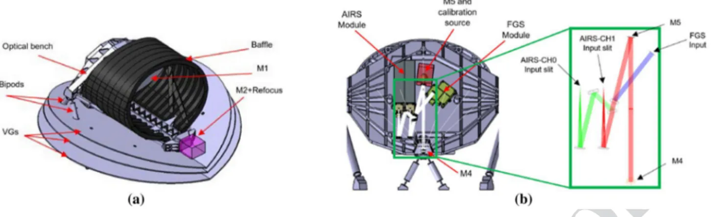
The ARIEL telescope consists of three mirrors (M1, M2, and M3) having optical power plus a plane mirror (M4) used to redirect the collimated beam towards the optical bench (OB) located on the back of M1 (see Figs. 5a, 7). The sec-ondary mirror is located at the end of a metering structure (beam) departing from the OB and it will be equipped, as a baseline, with a refocusing and tip/tilt mechanism. There will also be an eccentric bale around M1, internal vanes between M1 and M2, M2 and M3, ield and Lyot stops to
Fig. 3 ARIEL sky visibility.
Fraction of the year for which a given location in the sky (in equatorial coordinates) is vis-ible to ARIEL. Superimposed are known targets: in green, the very best, in red, the best, and in yellow, currently known transiting planets observable by ARIEL [6]
Fig. 4 ARIEL baseline payload
block diagram architecture 258 259 260 261 262 263 264 265 266 267 268 269 270 271 272 273 274 275 276 277
Author Proof
UN
C
ORRECTED PR
OOF
Journal : Large 12567 Article No : 175 Pages : 20 MS Code : CEAS-D-17-00051 Dispatch : 26-10-2017
V. Da Deppo et al.
1 3
control and limit both the out-of-ield and in-ield scattered stray light.
There is an additional M5 plane mirror (see Fig. 5b), which delects the beam on the OB. Following M5, a num-ber of plane dichroic mirrors are adopted to split the light and redirect it toward the ine guidance and spectrometer modules. These relay optics plus M5 constitute the common optics unit (COM).
Since calibration requirements are under assessment, additional hardware might be added within the instrument cavity. An IR calibration source based on the heritage of the JWST MIRI calibration system [18] and injected in the centre of the M5 mirror has been considered as the baseline solution.
The instrument modules AIRS and FGS are accommo-dated on the optical bench behind M1 (see Fig. 5b), enabling a direct view to deep space to provide direct radiative cool-ing. The units are thermally isolated by the VG shields and the critical elements such as AIRS detectors (see par. 3.2.2) are cooled by a dedicated radiator and thanks to an active cooler cold end integrated on the OB.
The detectors of the FGS, located in a single module box (the FGS box) are passively cooled to T ≤ 70 K by a dedicated radiator represented by the top surface that closes the modules cavity on the OB. This radiator, fully enclosed in the cold radiative environment set by the last V-groove, always faces the cold space during operations. The AIRS detectors must be operated colder, below 42 K, with the goal of reaching a temperature around 36 K, to minimize detector thermal noise. Maintaining this temperature, with a load of tens of mW, requires the implementation of an active cooling system. The cryocooler baseline relies on the Planck mission and EChO study heritage: a JT cold end fed by a Planck-like mechanical compressor using Neon gas isenthalpic expan-sion to achieve the required low temperature and heat lift [19].
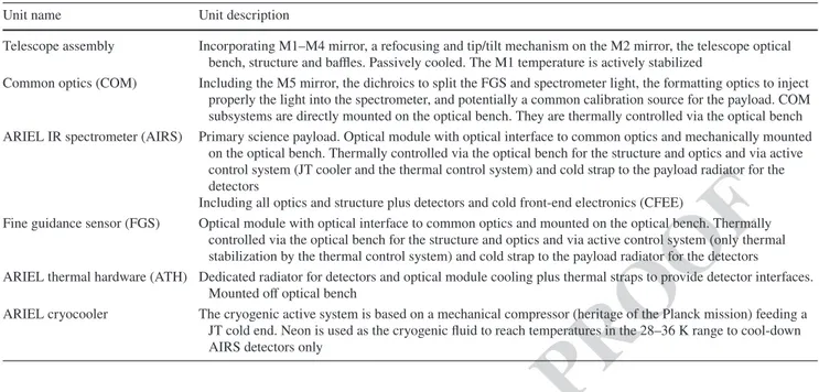
The main cold units are summarized in Table 2.
The baseline design of the PLM includes one potential active mechanisms in the payload. This is the refocusing mechanism on the telescope M2 mirror, which is used to ensure that the alignment and image quality of the tel-escope system are within the allowed ranges after launch and cooldown.
3.1.2 Service module architecture
The ARIEL warm units are integrated in the SVM. These include the payload electronics, which consists of three boxes that act as remote terminal units (RTUs) via Space-wire (ICU and FGS plus the cooler control electronics) to the S/C Command and Data Management System (CDMS). All commands coming from Ground, operational sequenc-ing and data storage are managed and implemented within the S/C CDMS.
The payload warm units are summarized in Table 3.
3.1.3 PLM and SVM interfaces: V-grooves, bipods, and supporting struts
The VGs are high-eiciency passive radiant coolers and pro-vide the irst stage of the PLM cooling system. The Planck mission has deinitely demonstrated their eiciency as pas-sive cooling systems. Parasitic heat from warmer sections of the S/C is intercepted by the VGs and radiated to space after multiple relections between the adjacent shields. To achieve this, VGs surfaces must have a very low emittance coating, i.e., a high relection/mirroring material needed to relect heat radiation. Only the upper surface of the last VG (VG3), exposed to the sky, is black coated with a high emis-sivity material to maximize the radiative coupling, and so the heat rejection to deep space. The ARIEL VG system consists of a set of three specular shields, composed of six
Fig. 5 In a, ARIEL telescope mechanical layout. In b, mechanical design of the OB with highlighted the optical path to the FGS and AIRS
modules; in the inset, there is a zoom on the common optics region
278 279 280 281 282 283 284 285 286 287 288 289 290 291 292 293 294 295 296 297 298 299 300 301 302 303 304 305 306 307 308 309 310 311 312 313 314 315 316 317 318 319 320 321 322 323 324 325 326 327 328 329 330 331 332 333 334 335 336 337 338 339 340 341 342 343 344 345
Author Proof
UN
C
ORRECTED PR
OOF
Journal : Large 12567 Article No : 175 Pages : 20 MS Code : CEAS-D-17-00051 Dispatch : 26-10-2017
An afocal telescope coniguration for the ESA ARIEL mission
1 3
half circles arranged in a “V-shaped” coniguration, angled along the diameter parallel to the S/C X-axis (see Fig. 4). A constant angle of 7° has been assumed as the inclination between VGs, resulting in a set of 7°–14°–21° for the three shields, separated by a gap of 100 mm at the vertices. VGs are mechanically designed as a simple sandwich of alumin-ium alloy (series 1000 or 6000) layers. A honeycomb cell structure 10-mm thick, with 10 mm (or less) cell size and ribbon thickness of 1 mm, is packed between two 1-mm-thick layers.
The PLM is supported by three bipods mounted onto the PLM/SVM interface plate. One bipod is centrally posi-tioned at the front of the telescope bale. The other two are on the rear side of the Telescope Assembly, support-ing the OB and the bale on two points. The VGs are also
mechanically and thermally attached to the three bipods plus the extra support provided by eight auxiliary struts (TBC). The need for these extra supports and their thermo-mechanical design will be investigated in the next phase of the analysis. Bipods preliminary thermo-mechanical con-iguration is based on the Planck design. They are assumed as hollow cylinders made of GFRP (R-Glass + Epoxy), a low conductive material with good structural properties. To increase their mechanical stifness, the inner volume of the cylinders is illed with low thermally conductive rigid foam. The eight extra supporting struts for the VGs are positioned in the outer boundary part of the PLM to support the radiators’ edges. They are designed as hollow GFRP cylinders extending from the SVM/PLM interface to the lower surface of the last VG.
Table 2 ARIEL cold payload units
Unit name Unit description
Telescope assembly Incorporating M1–M4 mirror, a refocusing and tip/tilt mechanism on the M2 mirror, the telescope optical bench, structure and bales. Passively cooled. The M1 temperature is actively stabilized
Common optics (COM) Including the M5 mirror, the dichroics to split the FGS and spectrometer light, the formatting optics to inject properly the light into the spectrometer, and potentially a common calibration source for the payload. COM subsystems are directly mounted on the optical bench. They are thermally controlled via the optical bench ARIEL IR spectrometer (AIRS) Primary science payload. Optical module with optical interface to common optics and mechanically mounted
on the optical bench. Thermally controlled via the optical bench for the structure and optics and via active control system (JT cooler and the thermal control system) and cold strap to the payload radiator for the detectors
Including all optics and structure plus detectors and cold front-end electronics (CFEE)
Fine guidance sensor (FGS) Optical module with optical interface to common optics and mounted on the optical bench. Thermally controlled via the optical bench for the structure and optics and via active control system (only thermal stabilization by the thermal control system) and cold strap to the payload radiator for the detectors
ARIEL thermal hardware (ATH) Dedicated radiator for detectors and optical module cooling plus thermal straps to provide detector interfaces. Mounted of optical bench
ARIEL cryocooler The cryogenic active system is based on a mechanical compressor (heritage of the Planck mission) feeding a JT cold end. Neon is used as the cryogenic luid to reach temperatures in the 28–36 K range to cool-down AIRS detectors only
Table 3 ARIEL warm payload unit
Unit name Unit description
Instrument control unit (ICU) Drives for spectrometer detectors and Instrument Control. Command and data handling, compression (if needed) and on-board pre-processing, formatting. I/O to CDMS. It acts as a Master for the TCU subsystem
FGS electronics (FGE) Drives for FGS detectors and FGS module control. Command handling. Data handling, compression (if needed), on-board pre-processing and data formatting. FGS data processing. I/O to CDMS via Spacewire
Telescope control unit (TCU) TCU is an ICU slave subsystem. Drives for heaters, thermistors (including those mounted on the OB) etc. Com-mands from ICU handling. Data formatting. I/O to ICU via I2C or Spacewire
TCU will be also in charge of controlling the refocusing mechanism on the M2 mirror and the IR Calibration source, thanks to its own driver sections
Cryoharness Harness connecting warm and cold payload units including internal harnessing and mating connectors Cryocooler compressor The active cooling system compressor is based on a Planck-like mechanical system, with vibrations control and
mitigation capabilities. Its task is to pressurize the low-pressure gas returning from the cold end feeding it back to the JT expander 346 347 348 349 350 351 352 353 354 355 356 357 358 359 360 361 362 363 364 365 366 367 368 369 370 371 372 373 374 375
Author Proof
UN
C
ORRECTED PR
OOF
Journal : Large 12567 Article No : 175 Pages : 20 MS Code : CEAS-D-17-00051 Dispatch : 26-10-2017
V. Da Deppo et al.
1 3
3.2 Science payload
As already mentioned, the science payload, in its cold part, is composed of: a telescope unit, a spectrometer unit and a ine guidance unit. The telescope will be described in the next paragraph. The primary payload is the spectrometer, whose scientiic observations are supported by the ine guid-ance system and photometer, which is monitoring the photo-metric stability of the target and allowing, at the same time, the target to be properly pointed.
In particular, to achieve the required photometric stability, a good pointing stability needs to be provided by the S/C during an observation. For this purpose, the FGS channels looking to the target star in parallel to the spectrometer will be accommodated on the payload and used by the AOCS.
Both the spectrometers and FGS will be mounted on the common OB.
3.2.1 FGS and its objectives
The Fine Guidance System (FGS) main task is to ensure the correct pointing of the satellite, to guarantee the target star is well centred on the spectrometer slit during all the observa-tion sessions. It will also provide high precision astrometry, photometry, and spectro-photometry of the target for com-plementary science. In particular, the data from the FGS will be used for de-trending and data analysis on ground. The sensor uses star light coming through the optical path of the telescope to determine the changes in the line of sight of the ARIEL instrument. The attitude measurement is then merged with the information from the star tracker, and used as input for the control loop stabilizing the S/C through the high performance gyros.
To meet the goals for guiding and photometry, four spec-tral bands are deined:
• FGS 1: 0.8–1.0 µm,
• FGS 2: 1.05–1.2 µm,
• Vis Phot: 0.50–0.55 µm,
• NIR-Spec: 1.25–1.90 µm including a prism element with low spectral resolution greater than 10.
The instrument has two detectors: one is shared by the FGS1 and Vis-Phot channels and the other one by the FGS2 and NIR-Spec channels. The baseline detectors are the standard substrate removed Teledyne H1RG [20], 2.5 µm cut-of wavelength, and 1024 × 1024 pixels with 18 µm pixel pitch. They have a QE greater than 50%, high technology readiness level (TRL) (9) and space heritage.
The information from all the FGS channels is used as a stellar monitor and to provide photometric information to constrain the Vis/NIR portion of the exoplanet spec-tra. The information from one of the FGS channels will
be used as the nominal FGS information to feed into the AOCS. In case of failure in the system, then the informa-tion from the other channels can be used. The spectral bands are selected from the incoming light using dichroic ilters.
The main requirement of the FGS is the centroiding per-formance of 10 milli-arcsec at 10 Hz to achieve centroiding to 1/10th of a pixel level. For the best support of the oper-ating modes, several centroiding and data extraction algo-rithms will be implemented, fully conigurable by parameter and command.
The FoV of the FGS on sky is: 17 × 17 as the inter-nal ield, usable for centroiding and 25 × 25 as the outer full ield maximum usable on sky, which corresponds to an internal FGS FoV of ± 0.19°. For the diferent channels, the plate scale ranges between 6 and 9 per pixel (for further details, see [21]).
The FGS could also be used during the commissioning of the payload to iterate and optimize the telescope focus and spherical aberrations by an iterative loop (with ground con-trol) feeding into the M2 mirror mechanism. To support this activity, a dedicated PSF imaging mode can be envisaged.
3.2.2 ARIEL IR spectrometer (AIRS)
The prime science payload for ARIEL is a broadband, low-resolution NIR and MIR spectrometer operating between 1.95 and 7.80 μm. The IR spectrometer can be split into mul-tiple channels but not at wavelengths with key spectral fea-tures for which overlapping on diferent channels is needed for spectra retrieval.
The baseline design foresees two spectrometers with independent optical channels and detectors: the irst one (CH0) covering the shorter waveband (1.95–3.90 µm), the second (CH1) the longer waveband (3.9–7.8 µm). As dis-persive element, prisms have been considered in the present design.
The beam reaching the AIRS slits has an F#18 in the spectral direction and F#12 in the spatial direction. The pixel scale of each AIRS channel depends on their optical design, i.e., on the focal lengths of the collimator and of the cam-era. The focal length of the cameras is diferent for the two channels. Some of the AIRS characteristics are reported in Table 4. For full details and complete AIRS performance predictions, see [21].
The baseline detectors for AIRS, as well as for the FGS, are the hybrid CMOS substrate removed H1RG from Tel-edyne. Given the diferent wavelength range, they have dif-ferent cut-of wavelengths. The CH0 detector is an H1RG standard type with a 5.3 µm cutof, while the CH1 detector is a custom NEOCam type [22], operated at a temperature of ~ 36 K using an active cooling system.
376 377 378 379 380 381 382 383 384 385 386 387 388 389 390 391 392 393 394 395 396 397 398 399 400 401 402 403 404 405 406 407 408 409 410 411 412 413 414 415 416 417 418 419 420 421 422 423 424 425 426 427 428 429 430 431 432 433 434 435 436 437 438 439 440 441 442 443 444 445 446 447 448 449 450 451 452 453 454 455 456 457 458 459 460 461 462 463 464 465 466 467 468 469 470 471 472 473
Author Proof
UN
C
ORRECTED PR
OOF
Journal : Large 12567 Article No : 175 Pages : 20 MS Code : CEAS-D-17-00051 Dispatch : 26-10-2017
An afocal telescope coniguration for the ESA ARIEL mission
1 3
For the AIRS, only a part of the detector will be used for detecting the spectrum as the spectrum size (see Table 4) is signiicantly smaller than the detector area.
Another option, presently considered for the detectors both for FGS and AIRS, is the adoption of European MCT detectors. In fact, there are speciic eforts underway within Europe (CEA/LETI) to develop a detector (640 × 512 or 320 × 256, 15 µm pixels) with cut-of wavelength at 8.2 µm at 45 K.
4 Telescope optical design
4.1 Telescope design requirements
The telescope optical layout has been designed to provide the optical requirements, as reported in Table 5, which have been derived by the mission requirements [11]. The require-ment on the collecting area of 0.6 m2 implies an entrance
pupil of the order of 1 m in diameter. The collecting area is related to the minimum intensity (magnitude) of the observ-able targets.
The design performance is driven by the requirement that the inal as-built quality of the telescope system has to be difraction limited at 3 µm over an FoV of 30 , i.e., equiva-lent to an RMS wavefront error (WFE) of 220 nm.
The requirement on the telescope throughput has been derived by breaking down the global system throughput
budget and including the lifetime degradation. The bro-ken-down budget ensures that all the channels are compli-ant with the mission requirements [21] [23]. To guarantee the required throughput without increasing the size of the primary mirror, that is the entrance pupil of the telescope, the optical design has to be unobscured. The unobstructed solution also assures that the energy in the PSF is primarily contained inside the irst Airy disk and not spread towards the secondary rings [24].
The wavelength coverage and the global FoV of the tel-escope are determined by the requirements on the instru-ments following the telescope, i.e., the FGS and the AIRS.
4.2 Telescope FoV determination
In the determination of the FoV for the telescope, there are three aspects to consider: the FoV required for the FGS, the FoV required for the AIRS, and the FoV required for the telescope itself. For each of these not, only the nom-inal scientiic FoV has to be taken into account, but also the extended FoV needed for accounting for misalignment [absolute performance error (APE)] or for channel calibra-tion. For example, in the spatial direction of the AIRS, an extended FoV is needed for monitoring the background (i.e., zodiacal and thermal background but also detector dark cur-rent). The FGS has to be able to acquire the source also in the “coarse alignment mode”, i.e., before the ine guidance loop has been closed, which implies a larger FoV for the telescope.
Moreover, an additional FoV requirement of 10 is intended to allow for of movements of the telescope with respect to the instrument optical bench (for example, due to launch loads, settling of the structure post-launch and dimensional changes on cooldown).
A 26.4 difraction limited telescope FoV is required to ensure that there is a well-resolved PSF at the centre of the spectrometer slit. A larger 37 telescope FoV is required to allow the FGS to acquire a star and centre it on the slit. The image quality level over this 37 annulus is still to be deined, but it can be of lower quality, suicient to allow the star centroid to be well enough resolved to be initially located and then brought to the centre of the FGS FoV, where the telescope image quality is better. This annulus has been indicated as the ‘FGS acquisition’ FoV. A still larger
Table 4 Summary of the main AIRS characteristics
Waveband (microns) Slit size spatial direction Spatial scale ( /px)
Slit size spectral direction Spectrum size (px2) Resolving power
CH0 1.95–3.90 1.26 mm (20 ) 0.22 0.296 mm (4.7 ) 270 × 64 100–180
CH1 3.90–7.80 1.26 mm (20 ) 0.45 0.465 mm (7.4 ) 100 × 64 30–65
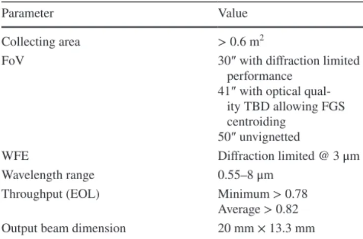
Table 5 Summary of the telescope optical requirements
Parameter Value
Collecting area > 0.6 m2
FoV 30 with difraction limited
performance 41 with optical
qual-ity TBD allowing FGS centroiding
50 unvignetted
WFE Difraction limited @ 3 μm
Wavelength range 0.55–8 μm
Throughput (EOL) Minimum > 0.78 Average > 0.82 Output beam dimension 20 mm × 13.3 mm
474 475 476 477 478 479 480 481 482 483 484 485 486 487 488 489 490 491 492 493 494 495 496 497 498 499 500 501 502 503 504 505 506 507 508 509 510 511 512 513 514 515 516 517 518 519 520 521 522 523 524 525 526 527 528 529 530 531 532 533 534 535 536 537 538 539
Author Proof
UN
C
ORRECTED PR
OOF
Journal : Large 12567 Article No : 175 Pages : 20 MS Code : CEAS-D-17-00051 Dispatch : 26-10-2017
V. Da Deppo et al.
1 3
telescope FoV, extending to 46 , is required to capture the slit background. There are no image quality requirements over this additional FoV; the only real requirement is for the FoV to be unvignetted, so that background photons reach the slit. This annulus has been referred to as the ‘background’ FoV.
However, this situation does not allow any margin for misalignment of the FGS and AIRS. They must be co-aligned to better than ± 5 in any case, or else the PSF can-not be located on the centre of the slit and in the FGS FoV at the same time. Some margin is also needed to allow to account for the fact that the telescope to OB alignment will be set to some datum on the optical bench, and there may be some residual misalignment between that datum and the individual FGS and AIRS instruments. It is reasonable to suppose that these misalignments will be small in compari-son with the ofset between telescope and OB, given that AIRS and FGS will be integrated on a single optical bench.
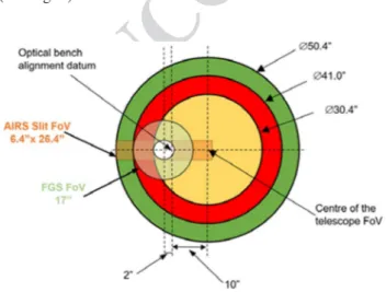
For the moment, it has been assumed that both the FGS and AIRS will be aligned to a datum on the instrument opti-cal bench (for example, an optiopti-cal reference cube) to within ± 2 , implying a maximum co-alignment error between the two of 4 . This reference cube has been assumed as the datum to which the telescope is aligned. This implies that a 4 margin on all of the telescope FoVs must be added to allow for these alignment errors. This gives the inal tel-escope FoVs, as shown in Fig. 6 and summarized in Table 6.
4.3 Telescope design characteristics
The baseline telescope design is an afocal unobscured eccentric pupil Cassegrain telescope (M1 and M2) with a recollimating of-axis parabolic tertiary mirror (M3). All the mirrors share the same optical axis. An M4 plane mirror is redirecting the exiting beam parallel to the back of M1, where the OB is located and the instrument will be mounted (see Fig. 7).
Note that the optical reference system (shown in Fig. 7) is diferent from the S/C one. The telescope is accommo-dated horizontally with its optical axis (Z) along the S/C
X-axis. The centre of the FoV of the telescope is inclined of 0.1° in the YZ plane with respect to the optical axis of the telescope deined by the mirrors common optical axis.
The system aperture stop/entrance aperture is located at the M1 surface. The M1 aperture is an ellipse with major/ minor axes dimensions of 1100 mm × 730 mm. The com-plete characteristics of the optical design are summarized in Table 7a, while in Table 7b, the parameters (radius of curvature, conic constant, of-axis, etc.) of the telescope mirrors are described.
The value of the angular magniication is forced by the need to conjugate the M1 aperture size with the desired output beam dimension at the exit pupil.
To be able to satisfy the required telescope throughput, a protected silver coating has been adopted as baseline for the mirror surfaces. In fact, silver coatings are able to provide more than 96% of relectivity both in the UV and IR wavelength regions. Many researches have been done, or are in progress, for studying and improving the high relective coatings for space applications, and in particular the protected silver ones [25–27].
A detailed trade-of for the material to be used for the telescope mirrors, speciically for M1, and telescope struc-ture has been carried out during the ARIEL assessment phase. The conclusion is that for the consortium provision of the telescope, the optimum solution is a telescope with mirrors and structure made from aluminium 6061 T651 alloy [28]. The viability of using aluminium as the base-line material for the telescope mirrors has been assessed during phase A by producing a pathinder M1 mirror [21].
The primary mirror will be lightened and its mechanical shape is studied to give high bending stifness both during manufacturing and in operating condition. The selected mounting system ensures isostatic thermal ixation of the primary mirror. M1 is supported directly by the OB via a nine-point whiletree structure, which is connected to the OB via three triangular mountings. The M1 mechanical coniguration is shown in Fig. 8.
Fig. 6 Final telescope FoV. All dimensions are to scale
Table 6 Summary of FoV requirements
Telescope FoV values are rounded to the nearest arcsec
Designation FoV (arcsec)
AIRS 6.4 × 26.4
FGS 17
Telescope: Difraction limited 30
Telescope: FGS acquisition 41 Telescope: Background 50 540 541 542 543 544 545 546 547 548 549 550 551 552 553 554 555 556 557 558 559 560 561 562 563 564 565 566 567 568 569 570 571 572 573 574 575 576 577 578 579 580 581 582 583 584 585 586 587 588 589 590 591 592 593 594 595 596 597 598 599 600 601 602 603 604 605 606 607 608 609 610 611 612 613 614 615
Author Proof
UN
C
ORRECTED PR
OOF
Journal : Large 12567 Article No : 175 Pages : 20 MS Code : CEAS-D-17-00051 Dispatch : 26-10-2017
An afocal telescope coniguration for the ESA ARIEL mission
1 3
A static analysis has been done to assess the deformation of the M1 surface due to gravity. Diferent mounting plate materials have been considered. With an Al 6061 mounting plate, the expected surface distortion PTV is of the order of 100 nm, which corresponds to approximately 40 nm RMS.
4.4 Telescope optical performance
The raytracing analysis and design optimization have been done by means of the raytracing software Zemax®. To assess
the quality of the telescope and determine the optical per-formance, since the telescope is afocal, the spot diagrams can be given using an ideal focusing paraxial lens with a deined focal length, or using the afocal image space option appropriate for systems with collimated output. Note that the
Fig. 7 Scale drawing of the
telescope—view in Y–Z plane
Table 7 (a) Summary of the telescope optical design characteristics, (b) mirror parameters description
(a)
Parameter Values
Optical concept Eccentric pupil Cassegrain telescope plus
of-axis paraboloidal mirror and folding. Afocal design
Focal length 14.17 m
FoV centre 0.1—of-axis YZ plane
Pupil size Ellipse with major axis 1.1 m × 0.73 m
Focal ratio @ intermediate telescope focus 13/19.4
Angular magniication − 55 (b) Optical element M1 M2 M3 R (mm) − 2319.5 − 239.0 − 491.5 k − 1 − 1.4 − 1 Of-axis (mm) (y direction) 500 50 20
Clear aperture radius (mm) Elliptical, 550 (x) by 365 (y) Elliptical, 56 (x) by 40 (y) Elliptical, 15 (x) by 11 (y)
Type Concave mirror Convex mirror Concave mirror
Fig. 8 Primary mirror rear side with the foreseen mounting scheme
616 617 618 619 620 621 622 623 624 625 626 627 628
Author Proof
UN
C
ORRECTED PR
OOF
Journal : Large 12567 Article No : 175 Pages : 20 MS Code : CEAS-D-17-00051 Dispatch : 26-10-2017
V. Da Deppo et al.
1 3
spot diagrams obtained with this second method have their size expressed in milliradians units.
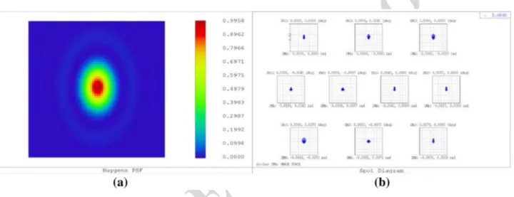
The nominal difraction PSF at 3 µm wavelength has an Airy radius, respectively, of 0.2 and 0.29 mrad in the X- and
Y-directions. A picture of the expected theoretical PSF is depicted in Fig. 9a; in Fig. 9b for comparison, the spot dia-gram all over the 50 unobstructed telescope FoV is drawn and compared with a box of 0.4 mrad size, so to show that telescope design is difraction limited at the 3 µm primary wavelength.
The telescope RMS WFE is always less than 26 nm over the 30 nominal telescope FoV (see Fig. 10); this value is well below the telescope difraction limit at 3 µm, i.e., 220 nm.
To assess the inal performance of the as-built telescope and its variation during the operation in light, a tolerance analysis has been done [21, 29, 30]. The telescope has been considered to be designed, realized, and integrated at room temperature in 1 g environment according to the raytraced theoretical layout. Being an all-aluminium instrument, it is expected to scale down when cooling down at the nominal operating temperature. To compensate for residual mechani-cal deformation of the telescope due to the cooling process, the secondary M2 refocusing mechanism can be used.
The tolerance analysis has taken into account the diferent parts of the realization and life of the instrument:
1. manufacturing, integration, and alignment;
Fig. 9 In a, PSF calculated at the telescope FoV centre for a wavelength of 3 µm depicted over a 1 mrad square box. In b, spot diagrams in the
afocal space; the scale (box) is 0.4 mrad
-30 -20 -10 0 10 20 30 20 25 30 35 RMS_wavefront_er (nm) FoV(")
(b)
(a)
Fig. 10 In a, RMS wavefront error ield map calculated for the 3 µm wavelength over the 30 nominal telescope FoV. Units are λ. In b, cross
section along the Y direction of the RMS wavefront error expressed in nm; in the X-direction, the wavefront error is constant 629 630 631 632 633 634 635 636 637 638 639 640 641 642 643 644 645 646 647 648 649 650 651 652 653 654 655
Author Proof
UN
C
ORRECTED PR
OOF
Journal : Large 12567 Article No : 175 Pages : 20 MS Code : CEAS-D-17-00051 Dispatch : 26-10-2017
An afocal telescope coniguration for the ESA ARIEL mission
1 3
2. launch loads and change from 1 to 0 g;
3. cooldown in orbit from ambient temperature to the nominal (about 50 K) operating temperature;
4. stability in light: short term (over one single exposure to about 10 h) and long term (over the whole mission operative lifetime).
For the manufacturing, integration and alignment phase optical element standard manufacturing and mounting toler-ances have been considered. The mirrors are foreseen to be equipped with a reference cube, or reference surfaces, and with respect to these references, the mirror local axis will be measured with high precision (∼ 10/20 µm in position and 2/4 in rotation). If after manufacturing, M1 will be measured and found to be out of the speciications; to avoid the time consuming process of re-working a 1 m diameter mirror, the possibility of re-optimize M2 will be consid-ered. The total impact of the manufacturing, integration, and alignment process on the RMS WFE is expected to be of the order of 40 nm.
The adopted alignment philosophy is to mount M1 and, then, with the help of the reference surfaces, measure its positon and orientation and use M2 as compensator to recover the optical quality. After the telescope alignment, the boresight direction will be measured with respect to the instrument reference cube, for example, using a theodolite setup [31], and used to co-align the other ARIEL modules.
To reduce the deformation efects induced by gravity dur-ing the alignment and tests on-ground, a slightly inclined position of the telescope, with the gravity acting parallel to the optical bench, is suggested to be adopted. The whole telescope structure should be rotated about 12° with respect to the telescope interface to SVM [21].
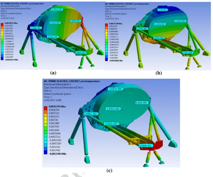
A preliminary thermoelastic analysis has been performed to verify the deformation of the primary mirror and the tel-escope structure during the cooling phase from ambient 293 K to the operating temperature. The considered operat-ing temperature map is the one calculated usoperat-ing the thermal model for the reference worst case condition (“Cold Case”, see the following section). The obtained resulting deforma-tions are reported in Fig. 11. The variation of the distance between the centres of primary and secondary mirrors is of about 20 µm along the X-direction, about 600 µm and 4.7 mm, respectively, in the Y and Z ones. These numbers are in line with the expected displacements; in fact, the mean Al6061 coeicient of thermal expansion (CTE) in the con-sidered temperature range is about 17 µm/m/°.
Choosing some reference points (nodes) on the primary and secondary mirrors and comparing the node expected positions, calculated with the simple scaling of the design, with the ones derived by the thermoelastic analysis, the residual deformations of the telescope have been derived. The telescope results to be rotated approximately 4 around
the X-axis, the distance between M1 and M2 is about 200 µm more than expected, and the estimated variation for the shape of the primary mirror is about 20 µm PTV. The irst efect can be recovered re-orienting the whole S/C, the sec-ond, and partly the third, by moving M2 via the refocusing mechanism. The residual WFE after refocusing is expected to be of the order of 200 nm.
For the stability in light, at present, the foreseen seasonal changes are estimated to be less than 1 K corresponding to an expected RMS WFE of about 130 nm. Anyway, if consid-ered necessary, the M2 refocusing mechanism can be used from time to time to recover the WFE changes. During one single exposure, i.e., up to 10 h, the temperature variation is negligible of the order of a few mK. The induced boresight errors will be recovered using the FGS.
The results of the whole tolerance analysis show that the telescope, thermally stable after cooldown and refocused via M2 mechanism, will have a WFE of the order of 220 nm RMS. The total RMS WFE error in light, including the sta-bility, will be within 250 nm. Comparing these results and the WFE budget, detailed in [21], it can be demonstrated that the telescope assembly will deliver the required opti-cal quality suitable to achieve the scientiic purpose of the instrument.
5 Telescope thermal analysis and control
The telescope is passively cooled to ≤ 70 K and its ther-mal control is based on a passive/active approach. A high-eiciency thermal shielding system (see Fig. 12) based on a multiple radiators coniguration can provide stable tempera-ture stages down to 50–60 K in the L2 orbit environment.
The telescope bale provides a large radiator area with a good view to deep space; this provides suicient radiative cooling to dump the parasitic loads from the PLM support struts, cryoharnesses, and radiative load from the inal VG. Temperature control of the mirrors is achieved by partial thermal decoupling from PLM units: each mirror is mounted on its supporting structure by insulating struts with a total conductance of less than 0.1 W/K. This coniguration will help in iltering out all potential instabilities with periods of the order of 10–100 s originated in the PLM.
For the primary mirror, the high thermal capacitance, due to its mass, will allow a higher level of passive iltering, damping instabilities at lower frequencies, i.e., with peri-ods of the order of few hours. The slower luctuations, with periods of the order of several hours or longer, that could be transmitted to the optics will be smoothed by the active control system based on a proportion–integral–derivative (PID)-type feedback loop.
The telescope will also incorporate contamination con-trol heaters on the M1 and M2 mirrors and on the PLM
656 657 658 659 660 661 662 663 664 665 666 667 668 669 670 671 672 673 674 675 676 677 678 679 680 681 682 683 684 685 686 687 688 689 690 691 692 693 694 695 696 697 698 699 700 701 702 703 704 705 706 707 708 709 710 711 712 713 714 715 716 717 718 719 720 721 722 723 724 725 726 727 728 729 730 731 732 733 734 735 736 737 738 739 740 741 742 743 744 745 746 747 748 749 750 751 752 753 754 755 756 757
Author Proof
UN
C
ORRECTED PR
OOF
Journal : Large 12567 Article No : 175 Pages : 20 MS Code : CEAS-D-17-00051 Dispatch : 26-10-2017
V. Da Deppo et al.
1 3
optical bench. These heaters will be active during the early orbit operations to ensure that the sensitive optical surfaces remain warmer than the support structure through the criti-cal parts of cooldown. A temperature delta of ~ 40 K will be maintained between the bales, which will act as a con-tamination getter for water and other contaminants being of-gassed by the PLM, and the optical surfaces. A pre-liminary calculation of the power required to maintain this temperature gradient shows that approximately 100 W of heater power is required during this phase. This would hold the sensitive surfaces at 200 K, while the bale cools below 160 K, where the H2O will freeze out.
A thermal analysis has been performed at PLM level. Both steady state and transient studies have been carried out for diferent boundary conditions on the SVM top plate and SVM radiative shield. The expected steady-state tempera-tures in the nominal operating conditions, corresponding to
the S/C orbiting around the Sun–Earth L2 point, have been calculated as well as transients induced by an abrupt change of the boundary conditions. In addition, the cooldown from ambient temperature to the operative condition in orbit, cal-culated over a 30 days period, has been simulated [32].
As a reference, the steady-state results obtained for the cold PLM in the coldest operative case (‘Cold Case’) are shown in Fig. 13. The ‘Cold Case’ corresponds to the situ-ation in which the payload reaches the lowest temperature resulting in the worst condition for what concerns the ther-moelastic deformation efects on the payload. The tempera-tures reached by all passively and actively cooled units are fully compliant with the requirements including margins. Figure 13a shows the temperatures of the radiator, OB, and bale, while Fig. 13b shows those of the AIRS and FGS CFEEs, detectors, and the JT cold end. Figure 14 reports a detailed view of the telescope assembly temperatures.
Fig. 11 In a, b, and c, telescope directional deformations, respectively, along the X-, Y-, and Z-axes resulting from the thermoelastic analysis.
Units are meters
758 759 760 761 762 763 764 765 766 767 768 769 770 771 772 773 774 775 776 777 778 779 780 781 782 783 784 785 786 787 788 789 790 791
Author Proof
UN
C
ORRECTED PR
OOF
Journal : Large 12567 Article No : 175 Pages : 20 MS Code : CEAS-D-17-00051 Dispatch : 26-10-2017
An afocal telescope coniguration for the ESA ARIEL mission
1 3
Thermal stability is one of the key issues of the ARIEL PLM thermal design. For this reason, an analysis case has been computed to check the impact on the PLM of a tem-perature variation of 10 K of the SVM platform conductive interface during a nominal observation run of 10 h. The corresponding total change (over the 10-h period) of the M1 node temperatures is less than 0.5 mK, even in the case of a sudden change (step function) or of a linear variation imposed at the SVM interface. The preliminary results of the analysis on the cooldown show that after 30 days,
the passive cooldown is concluded and the system can be considered in a steady-state thermal condition.
Summarizing the results of the thermal analysis, in rou-tine science operation, M1 operates at a temperature around 50 K with a very high level of thermal uniformity, better than 10 mK (see Fig. 14), achieved by passive cooling. Even for the whole Telescope Assembly, the total gradient between the mirrors and the structures results limited, of the order of 2 K, considering the dimension of the system. Moreover, transient simulations show that the telescope design, with
Fig. 12 PLM thermal
architec-ture scheme
Fig. 13 Thermal analysis results for the cold PLM in the steady-state ‘Cold Case’ in operating conditions. In a radiator, OB and bale
tempera-tures are visible. In b, the module boxes are hidden to show the AIRS and FGS CFEEs, detectors, and the JT cold end temperatempera-tures
792 793 794 795 796 797 798 799 800 801 802 803 804 805 806 807 808 809 810 811