Corso di Laurea Specialistica
in Tecnologie Informatiche
Tesi di Laurea
Generalized Trackball
and 3D Touch Interaction
Candidato:
Luigi Malomo
Relatori:
Dott. Paolo Cignoni Dott. Marco Di Benedetto
Controrelatore:
Dott. Giuseppe Prencipe
This thesis faces the problem of 3D interaction by means of touch and mouse input. We propose a multitouch enabled adaptation of the classical mouse based trackball interaction scheme.
In addition we introduce a new interaction metaphor based on visit-ing the space around a virtual object remainvisit-ing at a given distance. This approach allows an intuitive navigation of topologically complex shapes en-abling unexperienced users to visit hard to be reached parts.
1 Introduction 1
1.1 Touch Interaction . . . 2
1.2 Extended Trackball . . . 2
1.3 Outline . . . 3
2 State of The Art 5 2.1 3D Manipulation . . . 6
2.2 Camera Manipulation . . . 8
2.3 tBox . . . 11
2.4 Depth-Separated Screen-Space (DS3) . . . 13
2.5 Multitouch gestures for 3D object manipulation . . . 19
2.6 Navidget . . . 23
2.7 HoverCam . . . 26
2.8 Multiscale 3D navigation . . . 31
3 Touch-based Virtual Trackball 37 3.1 Virtual Trackball . . . 39
3.2 Camera manipulation with Trackball . . . 44
3.3 Multitouch based extension . . . 47
3.3.1 Techniques and implementation . . . 48
3.3.2 Directness, integration and separation of DOF . . . . 51 ii
3.3.3 Improvements and results . . . 53
4 MeshLab for iOS 56 4.1 User Interface . . . 57
4.2 Features . . . 62
4.3 Rendering . . . 64
4.4 Feedback & future work . . . 69
5 Generalized Trackball 72 5.1 Concept . . . 74
5.2 Curvature Constrained Surface . . . 76
5.3 Implementation . . . 79
5.3.1 kd-Tree distance field & normal field . . . 80
5.3.2 Approximated CCS . . . 84
5.3.3 Interaction . . . 85
5.3.4 Scale dependency . . . 92
5.4 Known issues and possible improvements . . . 97
6 Conclusions 99 6.1 Future work . . . 100
Introduction
Simple and intuitive interaction with 3D content has been a challenging problem since the dawn of computer graphics. At first, when realtime 3D rendering wasn’t possible, it was common practice to programmatically de-fine the position and orientation for the objects to be rendered offline. Later, when interactive rendering rates became common, the problem of mapping interactively 2D device input to 3D transformations became critical.
Today interactive manipulation of 3D objects/environment is a funda-mental part for all modeling and animation software but also for medical applications, videogames, CAD, Virtual Reality, etc. Despite being an im-portant research topic for the last 30 years, the problem is still actively discussed (see Chapter 2).
Conventionally the interaction is performed with devices providing two degree of freedom input, like the mouse. The core problem is how to map this limited interaction to 3D transformations, that have at least 6 degrees of freedom. More importantly, is the design of an interaction scheme that will result intuitive and natural for the user, even with limited input capa-bilities. Despite all the studies performed, this is not an easy task because for 3D interaction there are no obvious techniques that allows this. Over the years several solution were proposed and many of them became the de facto standard for interaction in specific application contexts.
In this thesis we face two aspects of this problem: how to design 3D
interaction techniques adapted to the touch paradigm and how to realize efficient and intuitive metaphors to easily inspect 3D virtual objects.
1.1
Touch Interaction
In the last years we have witnessed a growing interest in mobile computing. Multitouch enabled devices such as smartphones and tablets are every day more affordable and powerful. Currently they offer almost the same capa-bilities of a traditional desktop computer providing a user interface that benefits from touchscreen technology and is far more simple and immedi-ate. We can safely say that these devices have revolutionized the way people interact with machines.
Traditional desktop application that makes use of 3D interaction can be extremely complicated. Softwares for modeling and animation are often developed and improved during decades adding more and more features. The resulting user interface offers a lot of powerful instruments but it is often quiet difficult to learn how to use it (e.g. Blender software [1]).
For these kind of application users expect this situation and know that before getting to grips with the instruments offered they have to learn how to use them. Conversely, for mobile devices software, this is unacceptable. With multitouch interaction, people use fingers and expect to perform the interaction in the same way they would do for everyday real tasks. That’s because touch technology allows to directly operate on the screen, produc-ing a sensation of naturalness that must be reflected to the interaction tech-nique. For this reason, when designing a multitouch-enabled application, an easy and intuitive interaction scheme is a must. Users want to open the application and start using it with little or no training required, also for 3D applications.
1.2
Extended Trackball
What we want to realize is a set of 3D interaction techniques that improves the current state of the art. We will focus in particular to camera
manipula-tion (secmanipula-tion 2.2) for reviewing and inspecting complex 3D virtual objects. Taking into account the consideration made for multitouch-enabled devices, we want to provide innovative and easy to use interaction modes that pro-duce an enhanced user experience for both mouse-based and touchscreen interfaces.
Starting from the classical trackball approach for 3D manipulation, we want to provide a multitouch enabled version that is simple and easy to use. In addition, we want to extend the trackball interface concept to real-ize an advanced method that enables 3D surface navigation in a way that feels natural and provides the sense of space that is required during camera manipulation. This would allow to inspect 3D models at different scales, to review them comprehensively or inspect their details at close distance, focusing always on the object surface. To summarize, our final goal is to provide effective techniques that would enable anyone to review and analyze 3D objects without any training phase, even people that have absolutely no confidence with 3D interaction.
From these techniques would benefit both expert and unexperienced user. The latter would be provided with a usable manipulation scheme that virtually eliminates the computer-machine barrier, especially for touch en-abled implementation. The former would benefit as well from an enhanced interaction technique that increases the performance for camera manipula-tion tasks.
1.3
Outline
In Chapter 2 we will review the current state of the art regarding 3D inter-action and, more in depth, what are the best techniques to realize touch-based implementations. During the discussion we will categorize the differ-ent kinds of 3D manipulation, focusing on aspects that are clearly the most challenging for both touch- and mouse-based interaction.
In Chapter 3 we will describe the Virtual Trackball, a quite old mecha-nism which has now become the de facto standard for rotation of 3D virtual objects using only 2 degrees of freedom input. We will describe also a state
of the art mouse-based solution for virtual object inspection that uses the Trackball. At last, we will propose an innovative and user friendly technique that implements the same approach adapted to multitouch paradigm.
In Chapter 4 we will show how we realized MeshLab for iOS, a full featured mobile application for viewing 3D object that uses the multitouch interaction interface shown in the previous chapter. We will analyze in detail what are the major problems that arise building this kind of application. In addition we will highlight all the features that we implemented and provide some of the technical details for the rendering infrastructure.
In Chapter 5 we will propose the Generalized Trackball technique, an interaction scheme that allows unexperienced users to inspect topologically complex 3D models with extremely simple and intuitive gestures. We are going to explain the concept idea and the designed approach from a geomet-ric point of view. At last, we will show how we realized a very sophisticated implementation that achieves realtime performance.
State of The Art
In this chapter we will discuss the state of the art regarding touch-driven 3D interfaces. In order to help the reader understanding possibility and limitation of this kind of interfaces we will provide further examples of state of the art techniques not strictly related to touch environment. For the same purpose we will also provide a minimum overview of background knowledge related to 3D Manipulation.
While early studies on multitouch devices date back to the 1980s, re-search effort focusing this kind of interfaces increased only recently due to the massive spread of handheld touch-based devices (namely smart-phones and tablets). Beside this aspect, while 2D interaction techniques for touch/multitouch environments have been widely explored in literature, 3D touch interfaces have been investigated for few years only. As a conse-quence, it is really difficult to give a comprehensive overview of state of the art. The major problems arise due to the lack of uniform terminology and to the fact that most papers focus on limited aspects of 3D touch interaction only.
Please note that most of the work done in this field is very different from our solution. A large part of recent research studies are typically aimed to provide touch-based interfaces for 3D object manipulation tasks (i.e. trans-lation, rotation, scale). Our aim is to provide an intuitive and straightfor-ward interface for visualize and precisely inspect 3D models, manipulating
the view rather than the object examined.
2.1
3D Manipulation
Apart from touch related issues, 3D interaction keeps being a challenging argument for User Interface (UI) designers. The major problem lies in the different Degrees Of Freedom (DOFs) between inputs and desired manipula-tion, or rather, interactively mapping input with limited DOFs into a higher dimension 3D transformation. While in general we refer to 3D manipula-tion it is important to distinguish between proper Object Manipulamanipula-tion and Camera Manipulation. Given a coordinate system we can define an affine transformation for the object (commonly a 3D mesh) with 7 degrees of freedom:
• Position
3 DOFs determining location of the object (i.e. translation along X, Y and Z axes).
• Orientation
3 DOFs determining orientation of the object (i.e. rotation around X, Y and Z axes).
• Scale
1 DOF determining the dimension of the object (extensible to 3 DOFs for non-uniform scaling).
Object manipulation consists in controlling the transformation above and is often referred as Rotation, Scaling and Translation operations (RST, as in [2]).
Camera manipulation is the dual approach with respect to object 3D ma-nipulation: instead of manipulating the object itself we modify the way we look at it. Similarly, we can build a representation for an ideal perspective camera1
1An ideal lense-less camera with no intrisic parameters other than focal length (e.g.
• Position
3 DOFs determining location of the observer (the eye). • Orientation
3 DOFs determining the view direction and up vector. • Focal length
1 DOF determining the angular extent of the vision (the field of view). Camera manipulation consists in controlling the transformation above. Con-sidering a single 3D embedded object, if we fix a camera field of view it can be easily proved that manipulation of either camera or object transforma-tion permit to obtain the same results in terms of object visualizatransforma-tion. That said, the two approaches are conceptually very different but they are also complementary and can be used together. Object manipulation is very useful to perform transformation with relation to the world the object is embedded in, while camera manipulation is used for object(s) visualization and/or inspection purposes. A very real example of the combined use of different manipulation system is provided with any 3D modeling/animation software where is common practice to switch between the two modes to alternatively change the point of view and modify a 3D model.
Most of the research works done on such topics focus on one mode only and provide interaction techniques mapping user inputs to complex 3D manipulation. Much of the effort is actually focused on alternative touch/multitouch interfaces for RST transformation. Usually, in 3D desk-top software, the standard paradigm to perform such operations is the use of one or more widget. A widget is a proxy object embedded in 3D space that allows an indirect user interaction. Widgets are composed of handles or more complex gizmos and each one enables a constrained transformation for the object, typically one for each DOF (see fig. 2.1). For instance, as an object is selected a widget will appear; if the user moves the handle for X-axis translation the 2D screen-space inputs are mapped into constrained translation, thus the handle moves along the desired direction and the object with it. The same happens for gizmos related to other axes and transfor-mations. All 3D desktop software has widgets that behave greatly in the
same way. While it seems natural to implement such widgets on touch-screen environment, like any other mouse-input designed interface they do not perform well ([3]). This is mostly due to occlusion clutter caused by the fingers acting above the screen surface. Moreover, for precision tasks, con-ventional mouse pointing outperforms finger interaction. For these reasons it is necessary to redesign each interface for tactile capabilities, especially ones involving 3D manipulation.
Figure 2.1: The 3D transformation widget of the Blender software [1].
2.2
Camera Manipulation
For camera manipulation it is possible to make a further classification based on interaction metaphors, each referring to common concepts. As ssen in early studies (e.g. [4]), there are three kind of interaction for camera ma-nipulation: egocentric, exocentric and point-of-interest (POI).
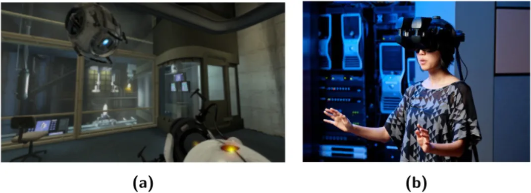
The egocentric paradigm allows to manipulate camera position and ori-entation as if the user is actually into the camera, looking out to the world. An example of this approach is the classical flying vehicle metaphor: user sits in an hypothetic aircraft that can be moved and reoriented in possibly any way. Another example for this kind of interaction is present in all First Person Shooter videogames (FPS) in which the player controls an avatar in first person. To be more precise, the user sees the virtual world through the
eyes of the avatar he controls (fig. 2.2a). Taking this concept to extremes, we can borrow an optimally suited example from virtual reality (VR). A VR 3D simulation with head mounted display(s) and sensors to detect head orientation/position is the perfect match (fig. 2.2b). In this case egocentric aspect of camera manipulation is enhanced by natural interaction of VR since there are no explicit input devices to interact with: as the user move his head the camera is transformed accordingly within the 3D environment.
(a) (b)
Figure 2.2: Egocentric camera samples: a First Person Shooter videogame (a), A VR immersive 3D simulation using a head mounted display (b).
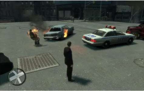
The exocentric paradigm is the dual approach with respect to egocentric interaction. The camera is outside the world looking into it. The focus shifts from the camera itself to the observed world (generally, but not exclusively, a single 3D object) so that camera manipulation occurs with relation to the object under examination. An interesting example of such interaction is the way we observe an environment trough a mirror: we move our head to examine the world as if we were external to the environment. A very popular technique implementing this pattern is the orbiting camera: camera looks always at a fixed target and can be orbited around it. This technique is commonly implemented in 3D applications with a Virtual Trackball (see section 3.1). This kind of approach is found also in many videogames (e.g. Third Person Shooter genre (TPS)): basically the camera always look at the playing character and can orbit around it to explore the world (fig. 2.3). For further examples see sections 2.7 and 2.8.
Figure 2.3: An example of Third Person Shooter videogame. Note the camera look-ing at the character.
The third and last paradigm is quite different from the previous ones. Egocentric and exocentric techniques often implies a functional mapping between the input DOFs and camera transformations. Point-of-interest techniques, instead, use the inputs to point out some portions of the 3D scene so that the camera can automatically transform in a proper way and provide optimal look for the specified location. This is a form of indirect camera manipulation as it offers controls with a higher level of interaction and it is often combined with one egocentric or exocentric approach as in [5] (see section 2.6).
From a psychological point of view is fascinating how well the human brain adapts to different paradigms of interaction. As far as inputs system is chosen consistently, after a little training people can easily interact us-ing any paradigm. The proof for this statement comes from 3D videogame world. Even if they are often not aware, gamers have to deal with many different camera manipulation techniques and yet most people have no prob-lem playing a flight simulator, a FPS, a TPS etc. Moreover many games mixes multiple interaction mode and yet users can still appreciate and play naturally. The real problems to deal with camera manipulation are two:
(a) which (combination of) paradigm fits better for the application needs, (b) how to map inputs to transformation to provide efficient and natural
interaction.
In the following sections we provide state of the art examples of 3D ma-nipulation techniques. The first three sections (2.3, 2.4 and 2.5) refer to touch-driven implementation of 3D object manipulation, while the remain-ing sections provide some significant examples of 3D Camera manipulation. Along with techniques description we will explain, in the order they appear, many of the technical aspects that are needed to fully understand certain type of 3D interaction. Similarly, we will focus also on most general ones, that apply to whole 3D manipulation argument.
2.3
tBox
Coh´e et al. [6] proposed the tBox, a 3D object manipulator widget specifi-cally designed for touch-screen devices. As we can see in fig. 2.4a, a classic widget doesn’t suit well for tactile interaction because: (a) it is hard to se-lect with precision a specific manipulation gizmo with a finger (the fat-finger problem), especially when all 9 interaction handles are visualized, and (b) the finger itself occlude the visual. The tBox is a cube shaped transfor-mation widget that enables to separately control 9 DOFs (axis-constrained RST operations) in a simple and natural way. The widget is embedded in 3D space and is always visible on top of model (fig. 2.4b).
Rotation is typically the most difficult operation to implement, thus for this purpose Coh´e et al. conducted a study to evaluate how touch-screen gestures can best approximate rotation for their proxy object (a cube). They found out that for rotating a cube around a specified axis users flick a finger crossing an edge parallel to that axis, so they adapted the interface to match this behavior. After the finger displacement is detected the algorithm converts it to a screen-space vector ~v and checks if ~v continuation intersects one edge E. If so the algorithm get the axis A parallel to E and checks if ~v is approximately tangent to A-axis rotation. In this case rotation around
(a) (b)
Figure 2.4: A classical widget for 3D transformation (a) and the tBox widget (b) overlayed on a 3D model.
axis A is detected and screen-space finger movement is linearly mapped to constrained rotation amount.
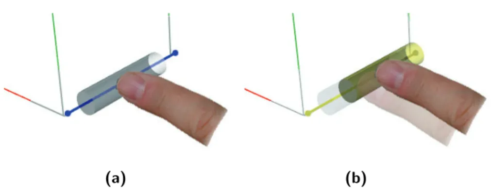
Translation activates instead with edge selection: to overcome fat-finger problem a coarse area around the edge is used for touch detection. Once the edge is selected, a 3D cylindrical slider appears and can be moved along the axis-constrained direction relative to the edge. To prevent sudden trans-lations the slider lies into a dead-zone as big as the edge. Once the slider reaches one edge border, the entire tBox move in that direction along with the model (fig. 2.5). This approach is very efficient: for a desired transla-tion in most cases there are two or three edges displayed, so the user can select and translate the model using the more convenient one.
Scaling interaction makes use of multitouch capabilities. As is common practice among tactile interfaces, even the tBox use the pull apart and shrink two-fingers gestures to respectively scale up or down. To uniformly resize an object is sufficient to trigger one of the two gesture inside the tBox. To perform a scale operation constrained to an axis it is sufficient to select two opposite edges on a cube face, each one with a finger, and move either one finger or both to shrink/expand the model along the axis orthogonal to the edges an parallel to the cube face containing both of them. Like translation, scaling too is very comfortable since most of the times there are one or two
(a) (b)
Figure 2.5: tBox translation interaction: the user selects an edge (a) and moves the slider. As soon as the slider touches an edge border (b) translation begins.
pairs of edges the user can utilize to resize the model along a desired axis. In order to provide a complete tool a camera manipulation system is im-plemented. With pull-apart and shrink multitouch gestures user can zoom the camera. With two-finger-drag it is possible to pan the camera: move the eye on the plane orthogonal to view direction (egocentric paradigm). Fixing a finger on a 3D point P and moving another finger on the screen orbits the camera around P (exocentric paradigm). Although with such instruments camera manipulation is crucial to allow change of view to a comfortable location, in tBox ([6]), as in many others papers, this aspect seems overlooked.
In conclusion Coh´e et al. had their interface tested by eight subjects without any training phase. It has been observed that most of them discov-ered by themselves almost all the capabilities of the tBox, giving proof of the “natural” interaction of their approach.
2.4
Depth-Separated Screen-Space (DS3)
In [7] Martinet et al. performed an in-depth study taking into account several aspect of tactile interaction and theory of 3D object manipulation. In their work they proposed the Depth-Separated Screen-Space technique (DS3), a 3D object manipulation approach designed for multitouch interac-tion and evaluated the latter against two other state of the art techniques:
Sticky Tools ([8]) and Screen-Space ([9]). For the research, rotation and translation transformations only has been taken into account: as a result 3D object manipulation has 6 DOFs.
Starting from previous studies (e.g. [10, 11]), they examined the con-cepts of perceptual structure of a task, control structure and the input device structure. It has been shown that each of this structure can be integraland/or separable. Integrality and separability are to be intended relatively to structure DOFs in the broadest sense: for perception consid-eration integral means that two or more DOFs are part of the same per-ceived operation, while for control and input consideration integral expresses whether is natural to move diagonally in an euclidean space determined by two or more DOFs. Separability refers to the opposite concept.
Human perception of 3D object manipulation is composed of two integral aspects: orientation and position. That is because we don’t consider the rotation transformation as a combination of three different operations; and that is the same for translations. Moreover, in the real world, we are able to perform them altogether; in fact, according to some studies, rotation and translation can be considered a whole integral operation. Input structure integrality or separability is more objective matter because is constrained by the specific device capabilities and possible human interactions with it. Control structure is a rather abstract concept laying in-between the two former: its characteristics depends on the mapping between DOFs of input to actual manipulation operations. On this point it is possible to operate creating different techniques for a pair manipulation ↔ device.
As for now, it is unclear which one between integrality or separability strategy is the best. Having perceptual structure that matches input and control structure should naturally lead to better performance, but there are contrasting researches retaining that separating control structure DOFs that are naturally integral may, in some cases, be the optimal solution.
From now on we’ll be focusing on 3D manipulation task performed with multitouch capable input device. One major aspect taken into account for this setup is the finger interaction directness. A finger interacting on the multitouch display is direct if its contact point on the screen keeps being
coherent to the screen-projection of the model as the finger move. For instance, a single finger-drag gesture over a 3D model that moves and keeps being under the finger, is a direct interaction (fig. 2.6a). A finger moving vertically that changes the z-position of the model is an indirect interaction (figs. 2.6b and 2.6c).
(a) (b) (c)
Figure 2.6: Finger directness: a direct interaction performing x-axis translation (a), an indirect interaction performing z-axis translation (b)→(c).
Starting from the work of Card et al. [12] Martinet and al. built a tax-onomy to classify 3D object manipulation using multitouch displays. The system can represent the number of fingers touching the screen, their di-rectness, the manipulation DOFs controlled, and whether the interaction is performed in an integral or separable way. All this information fits well in a table (figs. 2.7, 2.8 and 2.9): in the first column we have the entries showing the number of finger touching the screen and their directness, d for direct and i for indirect. We call each of these entries an interaction mode. Next we have 6 columns, each representing one DOF for 3D object manipulation: Tx, Ty, Tz for translation transformations along each axis and Rx, Ry, Rz for
rotation. To avoid ambiguity let us fix the Cartesian orthogonal coordinate system: x-axis belongs to screen plane and is oriented toward right, y-axis belongs to the screen plane too and is up-oriented, z-axis is orthogonal to the screen plane and points towards the user. Corresponding to each mode and DOF a circle is present if that mode controls that DOF; if the circle
is empty the interaction is direct otherwise an i is present indicating the finger interactions are indirect. Within each row circles connected with lines represent integral interactions: if two circles belongs to the same connected component they are integral otherwise they are separate.
Screen-Space technique is conceived starting from 2D touch-screen ob-ject manipulation: this type of interaction, as noted before, has been widely explored and 2D RST became the de facto standard. With one finger drag-ging the object translation is obtained. With two fingers instead it is pos-sible to rotate, translate and as well scale the object: this is achieved by binding each finger to its initial contact point on the underlying object. As the fingers move the contact points are constrained by fingers position resulting in the desired 2D transformation. The Screen-Space technique ex-tends this concept to 3D. For each finger 2D position Fi on the screen a ray
is casted onto the model, obtaining the visible point Pi. If we project Pi
to screen-space we obtain a 2D point P0
i that matches Fi. As the fingers
(Fis) move a solver builds a 3D transformation that minimizes the distance
between P0
i and Fi in screen-space. This algorithms basically aims to
manip-ulate a 3D object as if it was stuck under the fingers touching the display. Hanckock et. al in their formulation did not pose any constraint to the DOFs to be solved for, so it is possible to force each mode (i. e. 2-fingers, 3-fingers, etc.) to adjust a limited subset of 3D transformations (rotation or translation for specific axes). The Screen-Space technique instance used by Martinet et. al to compare against their solution is illustrated in fig. 2.8.
Sticky Tools technique is developed as the combination of three tools: sticky finger, opposable thumbs and virtual tools. Sticky finger is the evo-lution of 2D RST transformation: with one finger drag gesture 3D object can be translated along x- and y-axis. With two fingers the behavior is a special case of the screen-space technique above. Transformations are lim-ited to 4 DOFs: translation along all three axes (Tx, Ty and Tz) and z-axis
rotation (Rz). Compared to standard 2D RST manipulation the
behav-ior is the same, except for scale transformation which is replaced by z-axis translation (fig. 2.7). Opposable thumbs refer to the human ability to use thumbs to flip-over objects in our hand around x- or y-axis. The actual
Translation Rotation Mode Tx Ty Tz Rx Ry Rz i i i i Sticky Tools 1d 2d 1d + 1i 2d + 1i
Figure 2.7: Taxonomy for the Sticky Tools manipulation technique [8].
Translation Rotation Mode Tx Ty Tz Rx Ry Rz Screen-space 1d 2d 3d
Figure 2.8: Taxonomy for a Screen-Space manipulation technique [9].
Translation Rotation Mode Tx Ty Tz Rx Ry Rz i i DS3 1d ≥ 2d 1d + 1i ≥ 2d + 1i
Figure 2.9: Taxonomy for the Depth-Separated Screen-Space manipulation tech-nique [7].
implementation introduces an indirect finger (not necessarily a thumb) to achieve x- or y-axis rotation that can be used together with sticky finger 1d and 2d mode. As the indirect finger moves rotation is performed along the axis orthogonal to finger movement. Virtual tools is a set of tools for physics-based interactions between 3D objects and is not of much interest for the purposes of this thesis.
Depth-Separated Screen-Space technique (DS3) is the solution proposed by Martinet et. al as an improvement over the previous approaches. This solution relies on two main ideas:
(a) use indirect finger interaction to control z-axis translation, (b) separate control of translation and rotation with different modes. Both expedients hypothesize an improvement over performance and coordi-nation. The first one is achieved with the Z-technique ([13]), constraining z-axis translation to an indirect finger. Other interactions are implemented as a special case of screen-space solution that fulfilling their requirements. With one finger it is possible to manipulate Txand Ty DOFs only. With two
or more fingers manipulation is instead constrained to rotation (Rx, Ry and
Rz), achieved as for screen-space solution with a 3D transformation solver
algorithm. Taxonomy for this technique is illustrated in fig. 2.9.
Figure 2.10: Screenshot of the peg-in-hole task.
DS3 technique compared to Screen-Space and Sticky Tools solutions. A classic peg-in-hole docking task has been performed (fig. 2.10) by several subject under different conditions. The trials were performed varying:
• TECHINQUE: Screen-Space, Sticky Tools or DS3
• PRESENCE OF DEPTH: whether the task required z-axis translation • ROTATION LEVEL: simple (1 axis) or complex (multiple axes)
ro-tation
• ROTATION AMOUNT: large or small rotations required (120 and 30 degrees respectively)
The evaluation occurred analyzing task completion time, translation coor-dination, rotation coorcoor-dination, and most importantly DOF coordination for which they used different metrics to achieve a complete analysis (see [7] for details).
In conclusion, results saw DS3 technique outperforming the others under almost any aspect. They effectively showed that DOF separation, along with indirect control of z-axis translation, actually improves performance, coordination and overall user satisfaction. Although Martinet et al.’s work is very detailed, there are other aspects to be considered fulfill a comprehensive survey.
2.5
Multitouch gestures for 3D object
manipulation
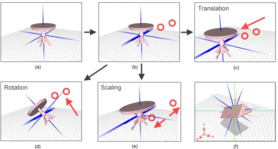
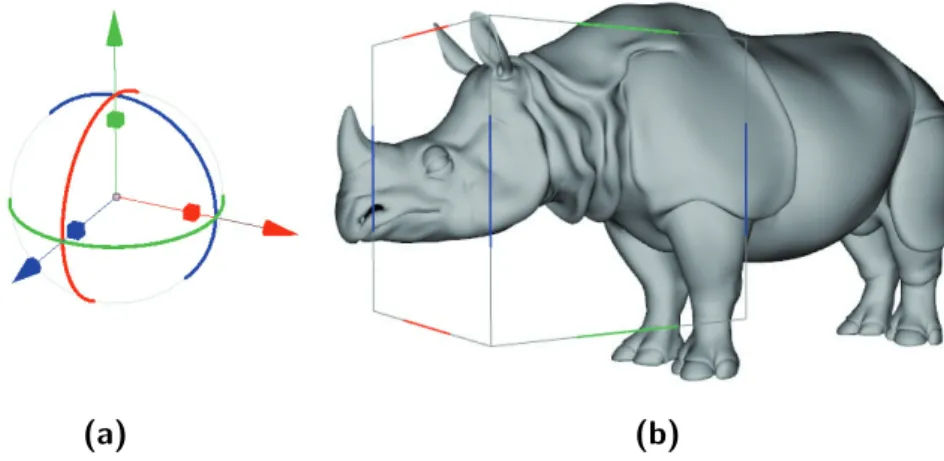
Recently Au et al. [14] introduced a very clever technique for 3D object manipulation that makes use of simple and intuitive multitouch gestures. The approach allows separated control of 9 DOFs of RST transformation (rotation, scale and translation along x-, y- and z-axis). The key idea is to use two indirect finger gestures to seamlessly perform any axis-constrained operation. As for widget based manipulation there are three steps involved to obtain the desired transformation: axis selection, operation selection and
amount selection (i.e., in reversed order, 45 degrees rotation around x-axis). Differently from widget based manipulation there are no gizmos on screen, but only candidates axes to select among. Axes are not handles and are used for visualization purpose only (fig. 2.11a and 2.11f). All interactions are performed with just two contact points on screen.
Axis selection is obtained putting two fingers on the touchscreen: di-rection vector ~d between the fingers contact points is calculated, then axes direction projected to screen-space P2D
a | a ∈ {x, y, z} are compared to ~d,
finally the axis a with a projected direction closest (parallel) to ~d is se-lected. Besides, there is no need to place the fingers onto the desired axis since interaction is indirect and the algorithm works for any screen loca-tion (fig. 2.11b). Once the two fingers are in place and the axis is selected
Figure 2.11: Multitouch interaction: (a) user interface with object axes visualized, (b) axis selection, (c) translate gesture, (d) rotate gesture, (e) scale pull-apart gesture, (f) user interface with all candidate axes visualized.
the subsequent gesture determines the type of operation (rotation, scale or translation). With a fingers moving parallel to selected axis, transla-tion is performed (fig. 2.11c). Translatransla-tion amount is proportransla-tional to finger displacement and changes interactively when fingers move. Translation is actually activated within a displacement threshold to avoid interference with
other gesture in presence of small finger movements. A similar threshold technique is implemented for rotation and scaling. Similarly to transla-tion, rotation is activated with fingers moving orthogonal to selected axis direction (fig. 2.11d). Rotation amount is as well proportional to fingers displacement. Scaling is instead activated with the classic shrink and pull-apart gestures (fig. 2.11e). Scale amount is determined calculating the ratio of current distance between fingers to the initial distance.
Besides classical object axes, world-space and screen-space axes can be selected for different coordinate system manipulation. When all this candi-date axis are present on screen, selecting among them become more difficult because screen projected direction may be very similar (fig. 2.11f). To over-come this problem object axes, which are commonly the most used, have priority over the others during selection.
This technique uses indirect interaction leveraging one of the advantages of touch-screen technology, that is, the strict coupling between finger and 3D model. Despite this weakness, the technique proved to be very efficient because it greatly reduces visual clutter during model manipulation and, since the visual feedback is interactive, virtually eliminates finger related imprecision in amount adjustment.
In addition to classic axis constrained manipulation the approach pro-vides plane constrained manipulation. Plane selection activates tapping the screen with two fingers once and then rapidly touching and holding the screen again. The algorithm is the same as for axis selection but instead, as the axis a is obtained from fingers position, selects the plane orthogonal to a. Subsequent fingers movement activates translation mode, mapping dis-placement into plane constrained translations. With shrink and pull-apart gestures scale mode is activated. As for single axis-scale, finger distance control scale amount but transformation is applied to both axes defining the selected plane.
Another impressive feature implemented is a context sensitive snapping tool which provides an easy to use technique for positioning objects rela-tively to each other. Drawing on the touch screen a free-form curve from one object to another snaps the first one to the second. Curve derivatives
on starting point (on the first object) and end point (on the second object) are used to select object’s planes to be snapped, with an algorithm similar to plane selection for plane constrained transformation. The first object is then positioned and reoriented in order to match the two planes associated to respective objects. Since the technique relies on axis orientation only, objects faces to be snapped don’t need to be visible from current camera point of view, thus reducing camera manipulation effort. This type of ma-nipulation is not interactive, it is actually planned. Besides that, it keeps its effectiveness since visual feedback is provided by the curve drawn on screen. A rich set of support operations complete the user interface: one finger tap on a 3D object selects the object, while tapping outside deselects all. Five finger pinch gesture (shrink or pull-apart) performs uniform scaling of currently selected object(s). A two finger rotate gesture, executed with any of x or y screen-space axis selected, achieves a 3D model rotation around view direction. A three finger pan gesture clone current selected object(s) and at the same time translate the newly made copy along the object axis that better matches fingers displacement. More importantly we have the one finger pan gesture which, performed outside any object, controls the camera with a trackball-like interaction (see section 3.1).
To evaluate the goodness of the user interface Au et al. implemented a widget based interface to compare their solution against. The widget ma-nipulator is a classic handle-based interface: for each axis one axis-oriented segment is present with two 3D spherical gizmos at each of its ends and two bars gizmos. Sphere movement along its axis direction performs translation, while moving two opposites spheres cause scaling constrained to the axis. Dragging a bar orthogonal to its axis performs a rotation around that axis. An experiment was performed submitting to test subjects a docking task. The participants were required to reposition, reorient, and rescale an object in order to match a transformed dummy present in the scene. The test was performed with both widget-based interface and the newly proposed one. Results proved that multitouch widget-free interface outperformed widget based one. Completion time and mean time spent editing the object were both lower. The average number of manipulation interactions performed
during the task was lower too: for rotation, translation and interestingly even for camera manipulation, which was implemented in the same way for both interfaces.
This solution is an optimal example for tactile based 3D interaction be-cause it shows how important is to design an interface targeting specifically the touch-screen devices, thus exploiting all the potential. As a plus, it uses only two finger gestures to achieve every transformation in a continu-ous way, with no virtual button required nor gizmos to manipulate. Beside the indirectness of control, which is indeed useful to prevent visual clutter, for most interactions the control structure matches the perceptual structure (feedback), providing a very natural experience.
2.6
Navidget
Hachet et al. [5] proposed a camera manipulation interface called Navid-get. The technique allows easy and fast camera positioning using a widget implemented for the purpose. Navidget implements the point-of-interest paradigm (section 2.2) but, differently from standard “go to” techniques, it enables specific camera control at the destination target.
POI techniques are usually targeted for environment navigation and present many advantages. Concerning input requirements a simple point-ing interface is sufficient, allowpoint-ing implementation with a range of devices (mouse pointer, touch-screen, pen stylus, etc.). Besides, they are fast and incredibly easy to use: with just a single click the desired camera trans-formation is performed. Another interesting property is lag independence: that is, computing camera transformation does not require real-time per-formance. After user interacts, indicating the point on interest, immediate feedback is not a must; a little lag is tolerated before the camera transitions (or moves immediately) to the target.
Other than advantages this kind of techniques have also drawbacks. The main limitation is surface dependency: camera can point to object surfaces only (exocentric approach), thus preventing a full camera control (i.e., ob-taining a view framing two side by side objects is almost impossible).
More-over, there are other issues limiting the camera possibilities. Surfaces that result occluded from the current point of view cannot be targeted as point-of-interest. In addition, for many implementations, user doesn’t manipulate directly the distance of the camera from the target, nor the angle of view direction, nor how the camera moves from one position to the desired one.
Differently from conventional point-of-interest techniques, which try to guess where user wants to focus starting from a point, Navidget allows to exactly specify which region to look at and how, all with a simple widget based interface. With any 2-DOF input device (mouse, touch-screen, pen stylus, etc.) and a sequence of push, move, release actions it is possible to perform any surface-focused camera manipulation. The technique described in the following assumes mouse based interaction but all the operations may be performed with touch based input too.
With Navidget pointing operation is achieved with a really intuitive metaphor. A circling gesture allows the user to point out a region of interest drawing a circle around it. Once the region is selected camera move towards the center of the circle. A policy must be defined to decide at what distance to stop. The first naive approach uses the 3D point on the center of the circled region, unfortunately the surface at that location may not exist (i.e. a hole). Another alternative procedure takes into account the most common depth value within the selected region and moves the camera to target that value. In this case many details enclosed in the circle that are closer to the camera will results out of frame after the POV changes. In the end the policy chosen for Navidget technique is the most conservative: the nearest depth value within the circled area is considered for camera movement. This makes sure that everything inside the highlighted region will fit the new camera frame.
Classical POI techniques allow the user to specify a target and try to guess the best view direction, generally using surface normals. Navidget instead uses a 3D widget to let the user change the view direction at the destination point. The 3D widget appears if the user, after a pointing operation, hold the finger on the screen (for touch based interface).
Virtual Camera
Hemisphere Border ring Cursor object Size actuators
Figure 2.12: The Navidget.
external surface, a border ring, four size actuators, and a virtual camera (fig. 2.12). Moving the cursor on the hemisphere surface adjust the point of view with a trackball style interaction (section 3.1). Virtual camera moves along providing visual feedback for the desired camera shot; in this way user can easily prevent occluded views. The border ring is introduced to easily place the camera orthogonal to current view direction: placing the cursor over the border ring is equivalent to put the cursor over the hemisphere border. Another interesting feature provides camera placing behind the region of interest. With a simple outside-inside gesture over the widget the hemisphere rotates behind the point of interest, allowing camera placement to observe the rear of 3D object(s).
Size actuators serves to resize the widget and altogether the camera-target distance of the desired point of view. Once the cursor is captured in-side left or right (top or bottom) actuators, horizontal (vertical) movements result in resizing while vertical (horizontal) movements quit the resize mode. Once a release event occurs within the hemisphere or the border ring, the viewpoint is smoothly moved from current location to the desired one. If release events occurs outside, the operation is canceled. Camera movement always lasts 3 seconds independently to the the distance to cover, providing to the user feedback over the distance traveled.
While the user adjust the viewing direction using the 3D widget a picture-in-picture interactively show the 3D scene as seen by the current virtual camera. The preview window offers inspection from the distance without the need to actually move the camera. Besides, it offers an interactive selection of the new point of view with an immediate feedback.
An experiment was performed to compare different POI techniques. The test subject were asked to inspect a scene filled with 3D cubes. The cubes have one face highlighted and users had to count some letters present on each face of these cube. Experiment results confirmed the value of Navidget approach. Users had no major problems using the interface and especially appreciated the circling gesture. Although the POI techniques are well suited for inspection purpose only, Navidget represents a major improve-ment with respect to classical approaches, providing a fast, easy and more precise interaction.
2.7
HoverCam
In this section we describe HoverCam, a quite innovative camera manipu-lation technique proposed by Khan et al. [15]. The following approach is very similar to a newly proposed technique that represents a large part of this work (Chapter 5).
HoverCam is an exocentric camera manipulation technique for navigat-ing around 3D objects at close proximity. Classical camera manipulation system implemented in almost any 3D Modeling/Animation software con-sists of three operations: orbiting (trackball-like interaction), panning (cam-era movement orthogonal to view direction) and zooming (cam(cam-era movement along view direction). The main idea is to provide camera manipulation merging these three camera control modes in a single operation, allowing the user to focus on model inspection without the risk of have the camera losing targeting on the model.
The three control modes maps to 6 DOFs in a contex unaware manner. One example of context aware camera manipulation technique can be found in FPS videogames: here, control is implemented with a walking metaphor
and egocentric manipulation allows the player (camera) to move within an environment. The context expresses with the concept of ground, up direction, height from the ground, and also with collision detection that avoid crossing 3D surfaces. The HoverCam approach aims to move the camera at a fixed distance from a 3D object while keeping it within the field of view, the authors called it camera inspection metaphor. To achieve this result with a limited 2 DOFs mouse based input some constraints need to be added to reduce the 6 DOFs to be manipulated. First constraint force the camera eye to have a fixed distance from the 3D model surface, that is, the closest point on the surface is always at the same distance throughout the whole manipulation. Second constraint keeps camera view direction normal to the observed surface. These creates a space of possible cameras that resembles to a shell around the object. This camera space can be explored with classical controls but not in a smooth way, as it is needed to switch interaction mode several times.
HoverCam implements a solution with an algorithm that moves the cam-era like a satellite orbiting around an object. Given an initial camcam-era with an eye point E0 and, at distance δ0, a look-at target L0 on the surface of 3D
model M the algorithm performs the following steps:
(a) Interprets mouse input vector i to generate new eye location E1starting
from the initial one,
(b) search on M the closest point C to new eye E1,
(c) turn the camera to look at C that becomes the new target L2,
(d) correct the eye-target distance δ1 between E1 and L2 to match initial
distance δ0 displacing E1 only, thus obtaining E2,
(e) clip the distance traveled to avoid sudden camera movements (read fur-ther for explanations).
This technique gives the feeling of hovering above object surface. It can be seen as center based camera manipulation, which focus exocentrically on a point (i.e. a trackball), extended to the surface.
HoverCam, as said earlier, provides proximity inspection so the tech-nique is used only at a certain distance from an object, while at higher
L0 E0 δ L1 E1 Object (a) E1 Object C (b) E1 Object C L2 δ1 (c) E1 Object L2 E2 δ δ1 (d)
Figure 2.13: HoverCam algorithm to compute new eye-target from an input move-ment.
distance classical control is provided. In order to manage a graceful switch HoverCam implements a camera blending technique to seamlessly smooth from traditional camera control to proximity navigation. A field of influence is present within a certain distance from the object. When the camera is within this range, it is captured by the field and slowly falls into a much restrained region closer to the object. This region spans from an inner to an outer distance limit, where HoverCam controls are fully activated. Once the camera has changed mode, the mouse wheel can control distance level from the surface; as soon as distance exceeds outer limit, camera slowly returns to classic control mode.
Camera eye and target are not enough to define a view. Although POV and view direction are defined, camera tilt value is unconstrained as up-vector is missing. Khan et al. developed four policies to define an up direction:
• Global
Keeps viewport up direction aligned to a globally defined up-vector. • Local
An egocentric mode that defines up-vector in a view dependent man-ner. Up changes with relation to camera movement.
• Driving
Up direction is considered as forward : while camera is moved, up vector tends to align to movement direction.
• Custom
Much like global policy, viewport up direction tends to align to vector values in a pre-authored up-vector field in order to provide the best view orientation according to camera position.
Input mapping can be either egocentric (push) or exocentric (pull). With push mode, moving the mouse from left to right moves the camera to the right. With pull mode instead, a similar movement moves the camera to-wards left, achieving a model movement to the right. The better interaction is pull as the mouse, due to the distance from the model, rests almost un-der the same portion of the model throughout the operation, giving a more natural feedback to the user. To avoid locking in model areas with high up-vector variance (e.g. the north pole of a sphere when using global up vector), internally the implementation keeps always a local up-vector to perform camera movement, while the policy chosen is applied separately to adjust view orientation.
The algorithm exposed works well with convex and slightly concave sur-faces, but with serious cavities, hole or protrusion fails to achieve smooth camera motion. This happens because after a camera move, closest query of step (b) may find a point very distant from the previous one. The step (e) in the algorithm serves to avoid this sudden motion, clipping to an input dependent value both the distances between old and new target L0L1 and
between old and new eye E0E1. There are still some cases in which this
approach may fail, e.g. the interior of an hemisphere with camera in the center, as closest point query doesn’t have an unique solution. To overcome this issue step (b) search is restricted to a volumetric wedge extended in direction of the input vector i (fig. 2.14).
Issues still remains when camera approaches surface corners. The vol-ume restricting closest point search cannot detect points on the surface approaching on the side, leading to strange camera path which breaks the
Figure 2.14: Closest point search is restricted to two volumes depending on input vector i: a trianglular wedge volume to limit search on a model sur-face region not too distant with respect to desired movement, and an obstacle detecting FOV aligned to i to anticipate surface approching on out-of-view sides.
motion continuity. To overcome this problem closest point query is extended to search within an additional obstacle FOV pointing in the input vector direction (fig. 2.14).
The closest point search is the most expensive operation for the algo-rithm, so it is crucial to have an efficient implementation. The query makes use of a precomputed hierarchical structure called sphere-tree, generated ad-hoc for each 3D model. The structure is very similar to an octree but subdivides the space in spheres rather than boxes. Spherical volumes are used because allow very fast distance computation, which results in rapid tree traversal. Spheres at each level become smaller and leaves of the tree structure are very small spheres wrapping one or very few primitives. Once the tree traversal reaches one of the leaves, ordinary closest point compu-tation is performed using geometrical primitives. A great benefit of this data structure is that can handle different geometric primitives other than triangles. With the same algorithm, navigation is allowed for point cloud or lines, as the only requirement is to change the distance function.
One of the limitation of this technique arises when moving too fast. Since camera movement depends on mouse movements a very fast mouse move could lead the camera to miss some feature (e.g. jumping over a large hole) or to go across the model surface. Besides, despite the efficiency of the sphere-tree structure, for very big 3D models (e.g. counting millions of
primitives) closest point queries might take a significant amount of time. Since the queries have to be performed for each mouse interaction, this slowness may result in a bottleneck that compromises interactive frame rates.
The technique has been tested by experienced users of 3D software. They had no problem to understand and use the interface and the overall impressions were that HoverCam provides better control than switching between classical pan-zoom-orbit modes. Despite that, users complained about the shakiness of the camera when inspecting low resolution models. This is a strong usability issue arising when a surface is too faceted : when the user look to the flat portion of a surface (a triangle) camera movement is equivalent to panning. When encountering an edge, instead, camera orbits around it. Spanning through a surface such as a triangular mesh, at a certain distance results in a rapid sequence of interleaved panning and orbiting operations which is perceived as camera shakiness. Besides, this issues is enhanced at great distance from the object because panning and orbiting sequences results in two different visualization feedbacks. With panning the model move on the screen, while orbiting keeps the object in the same position but changes the POV. Alternating large amount panning (at a significant distance) with rotation breaks camera motion smoothness. In Chapter 5 we analyze this aspect further and provide a smart solution to obtain a usable interaction technique.
2.8
Multiscale 3D navigation
McCrae et al. in [16] proposed a camera manipulation technique tailored to multiscale 3D navigation of large environment. Inspired by the grow-ing availability of large 3D dataset (e.g. Google Earth1) they developed a
smart solution to enable seamless context aware navigation of very large environment.
Many authors proposed multiscale navigation solutions mimicking real navigation experience like egocentric flying vehicle control, or ad-hoc
solu-1
tion like exocentric scene-in-hand metaphor ([4]). Others, to speed-up nav-igation and provide sense of orientation, introduced navnav-igation aids such as overlaid maps of the environment or reference landmarks.
Many others used approaches limiting user control freedom, stating that authors know best what are the interesting parts of an environment. Au-thored solutions provide assisted navigation guiding the user to focus on certain areas of interest. This is usually achieved with authored viewpoints, path-based, or content-constrained movement. Other non authored solution such as the ViewCube (Khan et al. [17]) offers exocentric navigation of an object with a cube-shaped widget that let the user choose among 27 pre-defined views. Other research works focus instead on path-guided camera manipulation taking into account obstacles using collision detection.
Solution proposed by McCrae et al. puts together both egocentric and exocentric camera manipulation providing at the same time a context de-pendent control to fit multiscale navigation needs.
Most context-aware camera manipulation techniques use classic CPU-based geometrical computation to calculate camera transformation. Dif-ferently from them, McCrae et al. introduced an image-space GPU based technique to probe the environment around camera position. The idea is to use the graphics hardware to rasterize the distance from the surround-ing environment into a compact image-based representation, the cubemap. For this purpose a GPU fragment shader is used to rasterize 3D geome-try distance from the camera view plane. The fragment distance values are normalized to the [0.0− 1.0] range corresponding to near-far clipping planes of the view frustum (a depth buffer is rendered). The cubemap is composed by six layers (textures) that are rendered using six perspective cameras located in the POV, each one facing one of the six canonical direc-tions. To cover the entire surrounding the cameras have a 90 degrees FOV, so that each image maps to a cube face (hence the name cubemap). For each texel of the cubemap it is possible to retrieve its relative position with respect to camera eye point, and therefore the distance. Cubemap sam-pling resolution has to be tuned in order to provide significant data. The samples dimension for objects at distance d are determined by the equation
2d/cubeSampleResolution. In the implementation the value chosen for the cubemap resolution is 64× 64 that produces a sample dimension of 10cm for objects at distance 3.2m, which is enough for the purpose. Moreover, 64× 64 resolution yields a very fast rendering of the scene and generate a manageable amount of samples. The cubemap strength is that it doesn’t re-quire any additional data structure nor pre-computation over the 3D scene. It is sufficient to update the cubemap at every frame or just when there is camera movement.
One of the application of the cubemap is scale detection. Tuning speed of the movement, like in a walking metaphor navigation technique, usually requires a previous knowledge of the environment. Cubemap, instead, al-lows real-time scale detection so that movement speed can be dynamically updated in relation to environment closeness. A very simple and robust ap-proach is to consider the minimum value present in the cubemap (the closest sample) and use the retrieved distance to estimate the scale. McCrae et al. also tried to use some smart averaging techniques to yield a more global estimate of the scale. Unfortunately the behavior is far less predictable so they stick to the conservative solution which is the best where there’s little or no previous information available.
For navigation purpose, it is crucial to prevent collisions. Rather than using classical collision detection algorithm, the cubemap information is exploited to prevent it. All the samples within a scale dependent radius δ are used to create a soft penalty force field to avoid obstacles during navigation. Geometrically, a sphere of radius δ centered in the camera eye is used as collision proxy producing a soft penalty force vector depending on where the sphere intersects the 3D environment.
Another aspect to consider is distance value precision. As said earlier cubemap faces are basically GPU depth buffers, and so to avoid precision loss for perspective projections, it is important to choose accurately distance value for near and far clipping planes. Besides, keeping static values for the two planes may result in unwanted clipping of near or far objects. To overcome the two issues the cubemap uses a dynamic view frustum that attempt to keep the distance of visible scene within a threshold between
near and far planes.
At loading time scene object shape is detected and a proxy low-polygonal object best approximating original shape is assigned to it (box, cylinder, cone, etc.). This feature can have multiple purposes. For cubemap gener-ation object at a significant distance can be rendered with their respective proxy objects instead of the original geometry, speeding-up the process.
Figure 2.15: Mouse-driven interaction scheme for multiscale 3D navigation.
We now describe the interaction techniques which are all based on mouse input (fig. 2.15). Left Mouse Button (LMB) click on a scene object initiate look-and-fly mode, flying the camera toward selected point on the model. Moving the mouse in this mode allows the user to look around the scene while still following the fly trajectory set. Subsequent LMB click retar-get the fly on newly selected objects. Right Mouse Button (RMB) click stops camera and exit the mode. When stationary, a LMB drag initiates HoverCam mode (Section 2.7), allowing the user to perform exocentric in-spection of geometry in the scene. A RMB drag enables instead egocentric look-around operation.
For look-around operation during fly, mouse movement are subject to a dead-zone in the center of the screen viewport. As mouse cursor exit this region, egocentric camera rotation is performed along the direction from screen center to the cursor and with speed proportional to the distance between the two points. Flying velocity is instead bounded to the scale of
the surrounding environment. After setting a target point Ptarget the vector
displacement for camera position PCam over a frame interval ∆t is:
∆Cam = (Ptarget− PCam)· ∆t·
cubeDistM in 2
where cubeDistM in is the non-normalized distance of the closest point to in the scene, extracted from the cubemap. The camera trajectory is not always straight because is influenced by the penalty force field to avoid obstacles.
As a complement to look-and-fly they implemented the push-out tech-nique to perform the opposite behavior. Activated with a RMB click, the push-out operation sets the collision detection distance δ = 3.0·cubeDistMin so that the collision force field pushes the camera away from the geometry. This works well for open space, or in closed space with a single aperture (a room with a window), but fails to find an exit camera path within more complex geometry.
Concerning exocentric navigation, McCrae et al. implemented an im-proved version of HoverCam (Section 2.7) that relies entirely on the cube-map. HoverCam navigation is performed with a LMB drag over a 3D object. The new implementation uses the cubemap to retrieve the closest point on the object, without explicitly testing his geometry. The shakiness issue highlighted in Section 2.7 is solved by using a mean-filter (smoothing) over the cubemap texels. This cuts off high frequency values and allows a con-tinuous camera movement. To be precise there are many situations that can still be problematic, but the overall camera shakiness is mitigated.
The last feature is framed zooming, a classical POI technique that uses surface normals to achieve zooming over the selected point. Holding shift on the keyboard and dragging over a 3D object an overlaid gizmo appears. A green arrow, normal to the pointed surface, provides feedback for the camera position and orientation when the LMB is released. In addition, a circular highlight area indicates the region that will be framed, and its radius (zoom factor) is controlled by mouse movement.
As for HoverCam, even for multiscale navigation camera up-vector is an important parameter that has to be tweaked to achieve appropriate envi-ronment views. For a large dataset like the earth the idea is to keep a global
north pole up-vector for long distance exploration, shifting to earth surface normal as the camera approach the ground.
The set of tools put together by McCrae et al. proved to be a very com-plete instrument for object/environment inspection/exploration. It proves that egocentric, exocentric and point-of-interest techniques can be effec-tively combined.
Touch-based Virtual Trackball
The Virtual Trackball (also known as Arcball or simply Trackball) repre-sents a milestone for the 3D interaction techniques. Since 1988, when Chen et al. [18] proposed the idea and the first implementation, it has been the standard interaction technique to achieve rotation transformation, es-pecially for camera manipulation. It is currently used in almost any 3D modeling/animation software, ranging from Maya to Blender. Before track-ball was proposed one of the methods to perform object rotation consisted of sliders, each controlling x-, y- or z-axis rotation. Other view-based inter-action solution presented 3 views of the object with orthogonal projection corresponding to xy, xz and yz planes: within each view only a single axis rotation is possible, reflecting changes in the other views. There were also techniques, not specifically targeted to traditional mouse input, that allow multiple degrees of freedom manipulation using non conventional devices. Sensor embedded in devices such as gloves, physical handles, joysticks, etc. allow direct mapping of multiple input DOFs to object affine transforma-tion. The trackball, instead, proposed a new technique to accomplish ar-bitrary rotation in a natural and straightforward way, using only 2 DOFs input devices. The solution stand out among other techniques because it only requires one view of the object, thus it can save screen real estate. It works with commonly available 2-DOFs device such as the mouse and, most importantly, provides direct and natural interaction.
Figure 3.1: A trackball device.
The trackball concept idea is to simulate with mouse input the behavior of a real trackball device (fig. 3.1). The transformation is achieved map-ping the 2D mouse movement over a virtual spherical surface, constraining the initial point of contact on the sphere to be stuck under mouse cur-sor. The spherical surface is often overlaid on the object, so the perceived behavior is that the object is bound to the sphere and mouse movement control the sphere rotation, which is then reflected to the object. Beside the sphere-object indirectness, the trackball is a direct method: it is an handle based interaction that uses a sphere instead of simpler gizmos. Using the model provided in Section 2.4, the trackball has 2 integral DOFs directly manipulating the 3 rotation DOFs.
Actually several implementation exists for the trackball: the first and most known is the one proposed by Chen et al. [18] which achieve rotation using a screen space projected sphere and 2D vector based rotation. The second implementation came with Shoemake [19] which enhanced the pre-vious version introducing quaternion rotations (for a quaternion overview see [20]). The third almost unheard version is the unpublished Bell’s im-plementation [21]. Despite the latter came before Shoemake version, this technique is the closest implementation to the state of the art.
In the following section we will only describe the most up to date im-plementation, remarking some of the issues found in [18] and [19]. For a
comparison and in-depth analysis of the three techniques see [22].
In the remaining part of the chapter we will describe a standard tech-nique to utilize the virtual trackball for camera manipulation interaction. Finally we will propose the adaptation of this approach for multitouch input, evidencing the choices made to obtain the best user experience.
3.1
Virtual Trackball
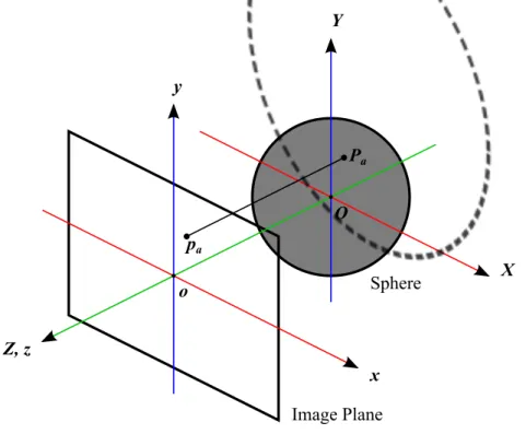
The original trackball implementation maps 2D screen-space points to a simple spherical surface. More precisely: a screen-space 2D input point pa = (xa, ya)T can be thought as a 3D point pa = (xa, ya, 0)T. The latter
is then unprojected, using a function m : R3 → R3, to a 3D space
embed-ded surface (a sphere fig. 3.2) obtaining a point Pa. When the user press
the mouse button over the surface at point p0 a 3D point P0 = m(p0) is
obtained. As the mouse move to a new position p1 a new 3D point P1 on
the surface is computed. Once we have P0 and P1 the ideal transformation
should perform a rotation that maps the initial point to the new point. If we consider the arc that connects P0 to P1 the rotation to be performed has
to match that arc which, in all cases, lies on a great circle passing through both points. Explicitly, a rotation axis A and an angle θ must be found to form a rotation transformation RA(θ) such that P1 = RA(θ)· P0.
There are basically four aspects that defines the trackball behavior: • the unprojection function m (usually a ray casting operation), • the surface to project to in 3D space,
• the choose of the axis A of rotation, • the amount of rotation θ (the angle).
The function m is basically an unprojection trasformation and can be performed considering orthogonal or perspective projection. It is pretty obvious to choose the projection that fits the intrinsics of the camera look-ing into the 3D scene so that cursor position always corresponds to the
Image Plane Sphere x y Z, z Y X Pa pa o O
Figure 3.2: Scheme for the basic trackball projection operation. xy screen-space points pa are mapped to XY Z 3D points Pa.
same point on the virtual 3D surface. Solution in [18] considers only or-thogonal projection because calculation is perfomed using 2D screen-space coordinates, while implementation in [19], despite quaternion calculation is performed, does the same for simplicity sake.
The surface considered for 2D to 3D point projection is normally an hemisphere with the outer surface facing the camera. In [18] points that map to the surface only are considered for trackball interaction. In [19] a point pathat doesn’t have a match onto the 3D surface maps to the point Pa
that lies on the plane passing through the center of the sphere and parallel to the image plane (the trackball plane of figure 3.5, see also fig 3.3a). Bell’s trackball and so state of the art implementation use instead a G1 surface
(continuous and derivable) to extend the mapping to all possible points of the screen. The surface is defined by a function that is a combination of the hemisphere used in the other techniques (fig. 3.3a) and an hyperbolic
![Figure 2.1: The 3D transformation widget of the Blender software [1].](https://thumb-eu.123doks.com/thumbv2/123dokorg/7567006.111179/15.893.276.639.422.675/figure-d-transformation-widget-blender-software.webp)

![Figure 2.7: Taxonomy for the Sticky Tools manipulation technique [8].](https://thumb-eu.123doks.com/thumbv2/123dokorg/7567006.111179/24.893.263.646.255.449/figure-taxonomy-sticky-tools-manipulation-technique.webp)