ALMA MATER STUDIORUM - UNIVERSITÀ DI BOLOGNA
CAMPUS DI CESENA
SCUOLA DI INGEGNERIA E ARCHITETTURA
CORSO DI LAUREA MAGISTRALE IN INGEGNERIA BIOMEDICA
Development of an instrumented customizable total
knee prosthesis for experimental tests
Elaborato in
MECCANICA DEI TESSUTI BIOLOGICI LM
Relatore
Presentata da
Prof. Luca Cristofolini Alessandra Ventresca
Correlatori
Prof. Bernardo Innocenti
Silvia Pianigiani, PhD
I sessione
“L’aquilone, per volare, ha bisogno del vento contrario”
Contents
Prefazione 1
Abstract 4
1 Introduction 7
1.1 The knee 7
1.1.1 Anatomy 7
1.1.2 Biomechanics 10
1.2 Total Knee Arthroplasty 12
1.2.1 Reasons of surgery 12
1.2.2 Designs 13
1.3 Instrumented knee implants: state of the art 16
2 Aim of the thesis 23
3 Materials and methods 25
3.1 Analytical study 26
3.1.1 Tibio-femoral joint 28
3.1.2 Patello-femoral joint 31
3.2 Design 32
3.2.1 Force sensing 33
3.2.1.1
Instrumented tibial tray 35
3.2.1.1.1
First design 36
3.2.1.1.2
Second design 38
3.2.1.2
Instrumented patella 40
3.2.2 Position sensing 41
3.3 Manifacturing 45
3.3.1 Six-axis load cell 45
3.3.2 Three-layers piezo-resistive position sensor 48
5 Discussion and future perspectives 64
6 Conclusions 67
7 Bibliography 69
1
Prefazione
La protesi totale di ginocchio (PTG) ha rivoluzionato la vita di milioni di pazienti e rappresenta il trattamento più efficiente nei casi di osteoartrite. Circa 700,000 procedure vengono effettuate ogni anno negli USA e questo numero è destinato ad aumentare. Inoltre, l'incremento della aspettativa di vita ha abbassato l'età media del paziente tipo, che richiede quindi una protesi più longeva e performante. Ad oggi infatti, la durata media di una protesi è di circa 10-15 anni, dopo i quali essa fallisce ed è necessaria una procedura di revisione spesso costosa e molto invasiva. Inoltre, spesso capita che, nonostante le immagini radiografiche non indichino alcun segno di fallimento, il paziente si dichiari insoddisfatto.
Per migliorare il design delle protesi e soddisfare le esigenze dei pazienti, è necessaria una
profonda conoscenza della biomeccanica del ginocchio. A tale scopo, i modelli numerici (analisi del corpo rigido e analisi agli elementi finiti) rappresentano un mezzo molto utilizzato dai ricercatori, per simulare ed analizzare varie configurazioni del ginocchio sano o protesizzato in modo non invasivo, veloce ed economico. In questo campo sono stati fatti numerosi progressi, tuttavia la modellazione numerica rimane un metodo molto problematico in quanto i modelli sono fortemente dipendenti da input esterni e hanno bisogno di essere validati sperimentalmente. Per superare l'incertezze dei modelli numerici, il ginocchio viene studiato anche attraverso metodi sperimentali. Un esempio è rappresentato dal Tekscan, sensore di pressione che misura
dinamicamente l'area e la pressione di contatto tra due oggetti in articolazione: esso viene spesso utilizzato nei test sperimentali sulle protesi di ginocchio per ricavare dati cinetici e cinematici. Tuttavia esso presenta numerose limitazioni: è fragile, costoso ed ha una risoluzione non ottimale. Un'altra alternativa sperimentale sono le protesi strumentate: prendendo spunto dai primi sistemi realizzati per l'anca, il primo prototipo per il ginocchio risale al 1996, quando Kaufman et al. misurarono la forza tibiofemorale assiale e il suo centro di pressione. Successivamente, D'Lima et al. hanno aggiunto un sistema telemetrizzato per la trasmissione dei dati, e realizzato un secondo prototipo che misura sei componenti di forza e momento. Parallelamente, un altro gruppo di ricerca, guidato da Bergmann, ha messo a punto un prototipo molto simile di protesi strumentata. In entrambi i casi, i carichi registrati vengono integrati con dati cinematici simultaneamente
acquisiti: nel primo caso, con un sistema di imaging fluoroscopico, nel secondo caso tramite gait analysis. I dati cinematici vengono combinati matematicamente con quelli cinetici in
2
postprocessing per dividere le componenti di forza tibiofemorale mediale e laterale. Questi dispositivi sono stati testati in vivo ed in vitro, permettono di misurare le forze interne del
ginocchio durante numerose attività, e attualmente vengono presi come standard di riferimeno per i carichi interni del ginocchio.
Lo scopo della tesi è stato quello di progettare e realizzare un nuovo prototipo di protesi
strumentata in grado di misurare la cinetica e la cinematica di differenti intercambiabili design di protesi durante prove sperimentali all'interno di un laboratorio di ricerca, su simulatore robotico di ginocchio. A differenza dei prototipi precedenti quindi, esso non è rivolto ad applicazioni
industriali, ma puramente di ricerca.
Dopo un accurato studio della letteratura, ed uno studio analitico preliminare, il progetto è stato realizzato ispirandosi ai prototipi di D'Lima e Bergmann, quindi il sensing della forza e della cinematica sono stati trattati separatamente. Il file CAD di una protesi commerciale è stato modificato, compatibilmente con le possibilità realizzative del laboratorio meccanico del dipartimento BEAMS dell'ULB (Universitè Libre de Bruxelles): lo stelo tibiale cilindrico è stato estensimetrato, diventando l'elemento sensibile di una cella di carico, fissata al simulatore robotico da un lato, e collegata all'inserto tibiale dall'altro, mediante un piatto tibiale. Il dispositivo è
completamente modulare quindi, una volta calibrata la cella di carico e fissata sul simulatore, è possibile testare differenti design di protesi semplicemente cambiando il piatto tibiale superiore. Inoltre, per la prima volta è stato considerata l'articolazione patello-femorale, fino ad ora sempre trascurata dalle protesi strumentate. A partire da un file CAD di un inserto patellare, è stato
disegnato un sistema che funge non solo da blocco di montaggio sul simulatore robotico, ma anche da sostegno per l'elemento sensibile della cella di carico, che è identico a quello dell'articolazione tibiofemorale ed è posizionato sul retro dell'inserto patellare.
Per quanto riguarda i dati cinematici, è stato progettato, realizzato e testato un sensore
piezoelettrico a tre strati, che rappresenta un metodo innovativo alternativo al Tekscan e ad altri metodi poco accurati ed invasivi fino ad ora utilizzati. Il test pilota ha mostrato una risposta positiva del sensore, il quale ha seguito dinamicamente i movimenti della protesi. Nello studio
dell'articolazione tibiofemorali questi dati sono fondamentali per suddividere il contributo di forza mediale da quello laterale.
A differenza delle protesi strumentate realizzate fino ad ora, i dati cinetici e cinematici potranno essere acquisiti e combinati attraverso un unico sistema di acquisizione, il quale può fornire in real-time la percentuale di distribuzione della forza tibio-femorale nelle componenti mediale e laterale
3
senza bisogno di elaborazioni successive. Inoltre il dispositivo è estremamente economico, non altera la cinematica delle protesi di ginocchio, ed è facilmente adattabile a quasiasi simulatore di ginocchio.
4
Abstract
Total knee arthroplasty (TKA) has revolutionized the life of millions of patients and it is the most efficient treatment in cases of osteoarthritis. About 700,000 procedures are performed each year in the USA and this number is expected to increase. In addition, the increase in life expectancy has lowered the average age of the patient, which then requires a more enduring and performing prosthesis. Currently, in fact, the average survival rate of a prosthesis is about 10-15 years: after the failure of the implant, a very expensive and invasive revision procedure is often necessary. In addition, it often happens that, despite the X-rays images do not indicate any sign of failure, the patient declares himself dissatisfied.
To improve the design of implants and satisfying the patient's needs, a deep understanding of the knee Biomechanics is needed. To this end, numerical models (rigid body analysis and finite elements modeling) are often used by researchers to simulate and analyze various configurations of prosthetic or healthy knee non-invasively, quickly and inexpensively. Much progress has been made in this area, however the numerical modelling remains a very challenging field because the models are highly dependent on external inputs and need to be validated experimentally.
To overcome the uncertainties of numerical models, the knee is also studied through experimental methods. An example is the Tekscan system, pressure sensor that measures dynamically areas and contact pressure between two articulating objects in: it is often used in experimental tests on the knee to derive kinematic and kinetic data.
However it has several limitations: it is fragile, expensive and has a non-optimal resolution.
Another experimental alternative is represented by instrumented orthopedic implants: taking cues from early systems made for the hip, the first prototype for the knee goes back to 1996, when Kaufman et al. measured the tibial-femoral axial force and its center of pressure (COP). Then, D'Lima et al., added a telemetry system for data transmission, and realized a second prototype that enabled the measurement of six force and moment components.
In parallel, another research group, driven by Bergmann, manifactured a similar device of
instrumented tibial tray. In both cases the measured loads must be integrated with kinematic data registered simultaneously: in the first case, with a dual fluoroscopic imaging system, in the second case by gait analysis.Kinematic data are combined mathematically with kinetic ones in
5
have been tested in vivo and in vitro, to measure the internal forces of the knee during many activities, and currently are taken as reference standards for internal loads of the knee.
The aim of the thesis was to design and manifacture a new prototype of instrumented implant, able to measure kinetic and kinematic data of different interchangeable designs of prosthesis during experiments tests within a research laboratory, on robotic knee simulator. Unlike previous prototypes it is not aimed for industrial applications, but purely focusing on research.
After a careful study of the literature, and a preliminary analytic study, the project was inspired by the prototypes of D'Lima and Bergmann, then the force sensing and kinematics sensing were treated separately.
The CAD file of a commercially available prosthesis was modified, depending on the possibilities of mechanical laboratory of the Department BEAMS of ULB (Université Libre de Bruxelles): cylindrical tibial stem was covered by strain gauges, becoming the sensing element of a load cell, mounted on robotic Simulator at one side, and connected to the tibial insert on the other, by means of an interchangeable tibial plateau. The device is completely modular, so once calibrated the load cell and mounted on the knee simulator, it can test different designs of prostheses just by changing the upper tibial plateau.
Also, for the first time it was considered the patellofemoral joint, until now always neglected by instrumented implants. Starting from a CAD file of a patellar insert was designed a structure that works as mounting block on robotic knee simulator, but also as support for the sensing element of the load cell, which is identical to that of the tibiofemoral joint and is located at the back of the patellar insert.
As for the kinematic data, was designed, manifactured and tested a three-layer piezoelectric sensor, which is an innovative alternative to Tekscan system and other inaccurate and invasive methods used until now. The pilot test showed a positive response of the sensor, which
dynamically followed the movements of the prosthesis. In the case of tibio-femoral joint study, kinematics data serve to divide the medial and lateral tibiofemoral joint force component.
Unlike instrumented implants performed until now, kinetic and kinematic data can be captured and combined through an unique data acquisition platform, which can provide real-time tibio-femoral force distribution percentage in medial and lateral components without the need for subsequent processing. Also the device is extremely cheap, does not alter the kinematics of the knee, and is easily adaptable to any knee Simulator.
1. Introduction
1.1 The knee
1.1.1 Anatomy
The knee is a multi-articular joint of the lower limbs that ensures the stability and the relative motion between the lower and the upper leg. It is considered as the most complex articulation of human body, not only because of its anatomy and geometry, but also for its biomechanics.
The knee is an assembly of three bones: femur, tibia and patella. They articulates making two joints working at the same time: the tibiofemoral (TF) joint, between the distal femur and the proximal tibia and the patello-femoral (PF) joint between the femoral trochlear groove and the patella. Also fibula bone is included, but only to connect the soft tissues between the lower and the upper leg. The bony architecture of the knee contributes to its stability, along with static and dynamic restraints of some soft tissues: ligaments, capsule, menisci, tendons and musculature crossing the joint. (Fig.1)
The femur is the longest bone of the human body, connecting the hip and the knee joints. The proximal extremity is composed by the head, the neck and the greater and the lesser trocanthers, the distal extremity splits in two condyles that articulates with the corrisponding tibial plateaus. So, the tibiofemoral joint is comprised of two condyloid articulations: the medial and the lateral one. The condyles are joined proximally by the femoral trochlear groove (patellar groove) that interacts with the kneecap bone, forming the patello-femoral joint. Simplistically, both the femoral condyles are cam-shaped in lateral profile, but they have different radius of curvature. The lateral condyle of the femur is smaller than the medial one, both in the antero-posterior (AP) and
proximo-distal directions: this contributes to the valgus and AP alignment of the knee. (Fig.2)
Fig.2: Inferior view of the right femoral distal epiphysis (left) and valgus alignment of the knee (right) .
The proximal tibia is separated by the intercondylar eminence into two asymmetrical
compartments: an oval, concave medial plateau, and a circular, convex lateral plateau. Observing the median section of the proximal tibia, it is possible to note that it has a posterior slope. (Fig.3)
Fig.3: Superior view of the right tibial proximal epiphysis (left) and particular of the tibial posterior slope from a lateral view (right).
The patellofemoral articulation is a sellar joint between the femoral trochlear groove and patella, also known as the kneecap or kneepan, that is the largest sesamoid bone in the body, triangular in shape. (Fig.4) It lies parallel to the coronal plane of the femur, incorporated in the quadriceps tendon insertion (patellar ligament), with the apex facing downwards. The patello-femoral joint is important to knee stability primarily through its role in the extensor mechanism. The kneecap plays two important roles for the stability of the knee: it increases the mechanical advantage of the extensor muscles by increasing the moment arm of quadriceps force, and allows a better
distribution of compressive forces on the femur by increasing the contact area between the patellar tendon and femur.
Fig.4: Anterior and posterior view of patella.
Each bone of the knee is covered by a thin layer of hyaline cartilage in the contact surfaces of the joint. The cartilage protects the underlying bone from damages and reduces the friction coefficient of the joint.
The distal femur and the proximal tibia are connected by the collateral (medial collateral ligament (MCL), lateral collateral ligament (LCL)) and the cruciate ligaments (anterior cruciate ligament (ACL), posterior cruciate ligament (PCL)), that are primary passive stabilisers against varus– valgus rotation as well as internal and external rotation. The patellar ligament connects the patellar apex to tibial tuberosity giving stability to the joint.
The menisci, two semi-lunar fibrocartilagineous pads, are located between the femoral condyles and the tibial plateaus. Besides the knee loads, they aid the joint lubrification spreading a fresh film of synovial fluid. Another important function is to distribute the forces and to reduce stresses on the structures of the joint during knee movements. [1,2]
Fig.5: Head of the tibia, superior view; menisci and ligaments inserts can be seen.
1.1.2 Biomechanics
The main roles of the knee are to allow locomotion requiring minumum energy from muscles and giving stability, and to transmit, absorb and redistrbute forces caused during the activities of daily life; it also acts as a pivot between the two longest bones of the human body, the femur and the tibia.
The complexity of knee joint behaviour is due to the interaction between three factors: ▪ Static stability – geometry and anatomy of the joint surface
▪ active stability – muscle contraction
▪ passive stability – ligaments, menisci and retinacula.
The kinematics of the knee joint is described through six degrees of freedom (three rotations and three translations) in a clinical joint coordinate system (Fig.6).
A simplified description of the knee is that is that it acts as a hinge in the sagittal plane. In fact the primary motion of the TF joint is the flexion-extension (FE) rotation about the epicondylar femoral axis, where it has a wide range of motion: starting from full-extension (0°), in which the tibial axis is alligned with the femoral axis, the TF joint can reach up to 160° of flexion. Also a medio-lateral (ML) translation occurs along epicondylar femoral axis. As the knee extends from 30° to 0°flexion the tibia externally rotates by up to 30°: this motion, called internal-external (IE) rotation, occurs around tibial long axis together with Joint distraction.
Fig.6: The six degrees of motion of the human knee joint.
Anterior-posterior translation and varus-valgus (or adduction-abduction) rotation occur along and about a floating axis, which is perpendicular to both femoral epicondylar and tibial long axes. [3] There are two mechanisms in the TF joint to take in account during the flexion-extension. First, as the knee flexes, contact moves posteriorly towards the posterior meniscal horns (roll-back) and tibial rotation occurs; however, the tibial plateaus are asymmetric (the medial plateau is more concave) so the A-P translation in the lateral side is greater then in the medial side, where the centre of contact remains almost constant. This second mechanism is the medial pivoting. (Fig.7)
At full TF joint extension the PF joint contact occurs at the distal end of the patella. During the flexion motion, the patella engages into the femoral trochlear groove: the contact area increases and moves proximally, by spreading the ever increasing PF joint reaction force over a larger area. This mechanism controls the magnitude of loads in the PF joint. [3]
Fig.8: Patello-femoral reaction force in full extension (left) and mid-flexion (right).
1.2 Total knee arthroplasty (TKA)
1.2.1 Reasons of surgery
The knee is one of the most stressed joints as each day is subjected to a large number of load cycles, which varies depending on the level of activity of the subject. Furthermore the forces acting on the articulating surfaces of the joint are very high (they may exceed 3-4 times the body weight (BW) [4]): they are the result of outside forces, such as the reaction force on the ground, and internal forces such as those that guarantee posture and mobility.
Disease or injury can disrupt the physiological conditions of the knee, so the joint is no longer able to sustain the high daily loads, resulting in pain, muscle weakness and reduced function.
The most common cause of chronic knee pain and disability is arthritis. Although there are many types of arthritis, most knee pain is caused by just three types: osteoarthritis, rheumatoid arthritis, and post-traumatic arthritis.
people too, and it is due to eredithary, mechanical or metabolic reasons. (Fig.9)
In rheumatoid arthritis (RA) the synovial membrane that surrounds the joint becomes inflamed and thickened. This chronic inflammation can damage the cartilage, not only in the knee, but also in other joints. A serious knee injury can cause a post-traumatic arthritis: bones fractures or meniscal tears or knee ligaments injuries may damage the articular cartilage over time. [2] Because of the arthritis, the cartilage that cushions the bones of the knee softens and wears away, so the bones rub against one another, causing knee pain and stiffness and reduction of mobility. When non-invasive drug therapies are not sufficient to improve the patient's condition, a knee prosthesis becomes necessary. Nowadays the market offers many solutions of knee prosthesis, available in different sizes, with the aim to satisfy the different pathological conditions and needs of patients.
Fig.9: Knee affected by osteoarthritis.
1.2.2 Designs
The knee replacement is a procedure where damaged cartilage and the underlying bone of the knee are replaced by artificial implants, and therefore only patient with sufficient cartilage damage in at least one of the three compartments (medial, lateral, and patello-femoral) should be
Depending on the number of replaced compartments, knee prostheses are divided into mono-, bi- or tri-compartmental, but total knee arthroplasty (TKA) prosthesis, in which all the compartments are resurfaced, is the most widely used mainly in cases of bilateral osteoarthritis.
TKA is composed of four elements (Fig.10):
1. Femoral component: it is usually made of metal (CoCr or stainless steel) and curves up around the end of the distal femur. It can be fixed to the bone by pegs or intramodullar systems.
2. Tibial tray: it is a flat metal (CoCr alloy0 or Ti) platform that resurfaces the proximal tibia. For additional stability it has a stem that inserts into the center of the tibial bone.
3. Tibial insert: it is a cushion of ultra-high-molecular-weight-polyethilene (UHMWPE) mounted on the tibial tray that acts as a linkl between tibial and femoral components. 4. Patellar component: it is a dome-shaped UHMWPE button that resurfaces the posterior
side of patella bone.
Fig.10: Knee implant components.
As has been mentioned above, there are several TKA solutions on the market, and they differs depending on the treatment of posterior cruciate ligament (PS or CR TKA), the mobility of
polyethilene insert (mobile or fixed bearing TKA) and the fixing method of prosthetic components (cement or cementless TKA).
Unlike the anterior cruciate ligament (ACL) , which is always cut during TKA, the posterior cruciate ligament (PCL) , responsable of anterior-posterior knee stability, can be preserved or not,
depending on his health status. In the first case the surgeon implants a CR (Cruciate retaining) TKA, stabilized by native ligaments. In the second case a PS (Posterior stabilized) TKA: an intercondylar
plug on polyethylene insert (Post) interacts with a horizontal bar (Cam) placed on the femoral component to replicate the function of the removed ligament (Post-Cam engagement). [5] (Fig.11)
Fig.11: CR TKA (left), and PS TKA (right).
In the fixed-bearing TKA, femur rolls on the cushion surface of the tibial insert, so one of the biggest complications is the wear of the polyethylene. To reduce this problem, in mobile-bearing TKA, the insert can rotate short distances on the polished tibial tray and its surface is more
congruent to the femoral component, to spread the loads. However, this type of TKA requires more support from soft tissues so it's suitable just for young or active patients; futhermore there are nostudies wich shows better durability or improvement in pain and function: so, fixed bearing TKA are usually more common. [6] (Fig.12)
Two types of fixation are used to hold the knee implants in place: Cemented fixation uses fast-curing bone cement (polymethylmethacrylate PMMA). Cementless fixation relies on new bone growing into the surface of the implants: to encourage this process, they are made of specific materials and often they are textured or coated. [7]
1.3 Instrumented knee implants: state of the art
Total knee arthroplasty (TKA) has revolutionized the quality of life for millions of patients and has proven to be a cost-effective and reliable treatment for symptomatic osteoarthritis of the knee. An estimated 700,000 TKAs are performed in the USA each year, making it one of the most common procedures annually performed with a projected increase in demand to over 3.48 million
procedures (601% of implantation rate) by 2030. [8,9,10]
Furthermore, TKA surgery is expanding to younger and more active patients [10]: because of their higher level of activities and functional demands, longer remaining life expectancy, and the greater prevalence of obesity [11] there is need to improve stability and longevity of the implants and to make them more performing.
In general, the TKA is not a permanent solution: its 10-year survival rate is considered 90%−98% and some studies even reported the 15 to 20-year survival rate is as high as 96%. [12]
After the failure of an implant, resulting in difficulties or pain during motion, the surgical procedure is repeated to replace damaged components: this revision TKA is often complex, expensive and invasive, so it's best to avoid it.
The most common causes of failure after TKA are polyethylene wear (45%), infection (26%) and aseptic loosening (17%) ; addictional causes are instability, extensor mechanism problems, aseptic necrosis of the patella, periprosthetic fracture, and arthrofibrosis. [12]
Considering the prosthesis together with the soft tissue envelope that surrounds the knee, any surgical error or excessive deviation from the standard knee anatomy will affect TKA performances: misplacement or wrong sizing, affecting loads on the interfaces and tensions in ligaments, lead to non physiological knee biomechanics. [13]
But sometimes, surgeons are not able to understand and explain the negative perfomances of the TKA, because the patient's medical images ''looks good'' but the patient is not satisfied: about 1 in 5 patients undergoing TKA are dissatisfied with the results of their surgery. [14]
For all these reasons, despite its enormous success, the TKA is still undergoing improvement. In order to solve the limitations of the TKA and to satisfy the patient's needs, manufacturers need to deepen their knowledge of knee Biomechanics as much as possible: this is the starting point for improving the design of existing prostheses and creating new ones.
For this purpose, numerical modeling is one of the most used methods, alone or in combination with experimental testing: the models can simulate various configurations of the knee and analyse its biomechanics for in a non-invasive, quick and cheap way.
In the rigid body analysis, the articulated bodies (bones) form a tree-like system: their motion is influenced by external forces (applied by the muscles, gravity, and the environment) and the constraints imposed by the joints. Current methods for estimating muscle, articular contact and ligament forces in the knee have evolved from first methods published in the 1970's [16,17], with the aim to solve the muscle redundancy problem (more unknown muscle forces than equations
available from rigid multibody dynamics). Furthermore, another issue is their strong dependence on external inputs: kinematic data, external forces (ground reaction forces) and muscle activation (EMG) are needed to correct the problem of inverse dynamic and they are often invasive or inaccurate.
In particular, kinematics data are achieved by different methods including in vitro cadaveric measurements, gait analysis with motion systems, roentgen stereophotogrammetric analyses, quasidynamic MRI testing, and in vivo video fluoroscopy. Studies on cadaveric knees suffer from the difficult estimation and setting of the loading conditions in vivo and from the inability of actuators to reproduce loading and motion conditions accurately. Roentgen
stereophotogrammetric analyses often have been performed under nonweightbearing conditions but are quasidynamic. In the instrumented gait analysis, owing to motion of the skin markers relative to the underlying bone, critical motion artifact may occur [17]. In vivo videofluoroscopy enables the reconstruction of three-dimensional (3D) position and orientation (pose) of the knee prosthesis components more accurately unhindered by the soft tissues around the joint.
Registration algorithms estimate the pose of the components from single-plane projection views on fluoroscopic image series. This method has the advantage of testing under in vivo,
weightbearing, fully dynamic conditions, while subjects perform various motor tasks. In addition to standard joint kinematics, fluoroscopybased 3D techniques have largely been used but often they are non accurate.
calculated forces exist. Morrison calculated joint forces of 2-4 BW (body weight) during level walking [15]. More recently, using a similar computational approach, most studies report the same range of values [19,20,21] , other studies calculated contact forces of 5 BW (Mikosk, 1988) and even up to 6.7 BW .[22,23]
Finite Element Modeling (FEM) is the most recent numerical technique: such analytical method allows researchers to change certain parameters of potential influence (e.g. Different designs or sizes or malallignment[24]) and investigate their effect under standardized conditions simulating knee function in a non-destructive and repeteable manner.[25,26] Lastly, a novel technique utilizes real in vivo 3D kinematics obtained from fluoroscopy as input for FE models of the prosthes. [18] Neverthless, modeling is a challenging topic because to obtain accurate models that allows
relevant conclusions, they have to be validated: experimental measurement of knee biomechanics provides a valuable opportunity for models validation.
To overcome uncertainties of numerical models or to validate them, the forces acting on the human skeletal structure can be measured with pressure sensing devices. Among such devices, the Tekscan system (I-Scan TM, Inc., South Boston, MA), is the most common used in biomechanical applications. Force is measured in real time at each sensel of the sensor, that is electrically isolated, contact areas can be measured and thus pressure profiles can be represented on the computer screen during loading in real time. The Tekscan system offers several types of sensors for pressure measurement, depending on the dimensions of sensing areas. It is commonly used for the tibio-femoral joint analysis, to study the polyethylene wear in the tibio-tibio-femoral insert [27] or to validate FEM models [26,28], and it is a particularly useful tool for the analysis of patellofemoral joint and post-cam engagement, why difficult to study analytically and still poorly understood.
The experimental tests on different types of implants show that the PF force is incredibily high, up to 7.5 BW during squat, and mostly affected by patella height (increases in patella-alta
configuration[29]) and by anterior tibial component( decreases at a mean of 2.2% for every millimetre of posterior translation of the tibial component [30] ).
As regard the post-cam engagement, the esperimental tests on different designs show high contact force (1.4 BW) and stress [31] and a positive correlation was found between contact force and initial contact angle. [32]
Even with its good characteristics as the wide range of loads measurement, the capability of produce realtime data and the great accuracy, the Tekscan system has been shown to have some inherent variability when comparisons are made across different measurement systems. The
measured errors for the Tekscan system ranges from -2% to 3% for average pressure and contact areas [33]. Furthermore, this sensor is quite bulky, fragile and expensive.
Another alternative for the measurement of forces acting on the human skeleton in vivo, is by means of instrumented orthopaedic implants.
This approach has been used first for instrumented hip prostheses. Strain gauges attached to implants or directly to bone and connected by transcutaneous wires to outside measuring systems have been used, but this solution is suitable only for short-term postoperative recordings [34,35,36]. The first implantable telemetrized device for TKA analysis was an instrumented massive distal femoral replacement for patient suffering from cancer. A mathematical approach was still
necessary to get the loading data at the knee joint line level and the estimated forces in the knee joint (2.2, 2.5 BW) during level walking were smaller than those calculated anatically.[37]
To measure the tibio-femoral contact force directly, instrumented knee implants were also
developed, to perform experimental tests in vivo and in vitro (on cadaveric specimens or on Knee robotic simulators).
An initial design developed by Kaufman in 1996 [38] and tested in vitro in cadaveric studies [39], measured the total axial force and calculated the center of pressure as the point about which all applied forces had zero moment. The customized transducer consisted of a standard tibial
component to which were appplied four uniaxial load cells instrumented with strain gauges in a full Wheatstone bridge: the output signals from the transducers were connected directly to the data acquisition system.
This prototype was improved by D'Lima et al. inserting a radiofrequency transmission of data, and and it was tested in vitro [40] and intraoperatively [41]. In addition, the system also worked during in vivo tests [42]: tibial force data were recorded simultaneously with motion capture data and vertical ground reaction forces from force plates during walking, chair sit to stand and stand to sit, stair ascending and descending, squatting from a standing position, and golf swings. Furthermore, there was a first effort to calculate the percentage of axial force in the medial and in the lateral side using kinematics and force data. For all activities, total compressive load exceeded 2 times body weight, and for most activities 2.5 times body weight (approximately 3.5 BW during stair ascending and descending). Most activities placed a greater load on the medial compartment than the lateral one. [43]
A second design developed by the same group enabled the measurement of all six force and moment components [44]. Based on a commercially available prosthesis, this instrumented tibial
tray was an assembly of two structural components: the proximal section, holding the
polyethylene, was connected to the distal component cemented to the tibia. The proximal section was the sensing element instrumented with strain gauges, signals of which were transmitted by telemetry. (Fig.13)
Fig.13: Multi-axis instrumented prostesis by D'Lima et al. [44]
In 2008 the same research group made the first simultaneous in vivo measurement of six-DOF tibiofemoral forces (with the instrumented implant) and 3D articular contact kinematics (with a dual fluoroscopic imaging system) in TKA patients. The combination of these two data was used to determine the percentage of tibio-femoral loads in the medial and lateral side.
During walking, total axial forces between 1.8 and 2.8 BW were measured and in general the loads were higher in the medial compartment. During all investigated activities, the shear forces were substantially lower than the axial forces. Peak anterior shear forces of 0,3 BW were observed during walking. [45,46]
This prosthesis is currently used for the annual “Grand Challenge Competition to Predict In Vivo Knee Loads’’ based on a series of comprehensive publicly available in vivo data sets for evaluating musculoskeletal model predictions of contact and muscle forces in the knee. The data sets includes tibial contact-force from this instrumented tibial prosthesis, video motion, ground reaction force, muscle EMG, muscle strength, static and dynamic imaging, and implant geometry data.
having access to the corresponding in vivo measurements. [47]
Another group, led by Bergmann, has developed in 2007 an instrumented telemetric tibial tray, also in this case composed by two concentric hollow tibial stems (Fig.14). The proximal plate carried the snaplock mechanism for the tibial polyethylene insert, whereas the distal plate is cemented onto the resected tibia. All electronics and strain gages are housed in the cavity of the inner stem, are powered inductively and transmit the six load components telemetrically at radio frequency with a measuring error below 2%. [48]
This instrumented tibial tray was tested in vivo to measure the tibio-femoral contact forces and moments [49,50]. During the measurements, the patient’s activities are video-taped and recorded together with the loads. Additionally, gait data was also captured to split mathematically the medial and the lateral contribution of the tibiofemoral force, in post-processing. Synchronous load and video data from many activities can be accessed from the free public
databasewww.Orthoload.com [49]. The loads were measured in the Julius Wolff Institute of the Charité in Berlin directly in patients by using this instrumented implant. OrthoLoad supplies numerical load data and videos, which contain load-time diagrams and synchronous images of the subject’s activities.
In order to provide a smart prosthesis design which does not impose major modification in the mechanical design of the commercially-available prostheses and gives not only in-vivo force information but also accurate kinematics, in a recent study of Arami et al. all the electronics were housed in the polyethylene insert (PE) of the prosthesis.
For measuring the kinematics of the prosthetic knee, a magnetic measurement system was designed, consisting of a permanent magnet attached to the femoral part (FP) and three 3D anisotropic magneto resistance (AMR) sensors inserted in the PE. Furthermore, strain gauges were positioned inside the PE to measure the total force applied to the prosthesis and the medial-lateral imbalance.
The proposed instrumentation is a promising system for monitoring medical implants, but overall during the surgical operation to help the surgeon in the balancing phase, because his range of measurement is quite low. [51]
2. Aim of the thesis
All previous studies reveal a certain disparity between the knee forces typically estimated by numerical models and those experimentally measured with instrumented implants. Moreover, the instrumented prosthesis developed until now presents several limitations: the medial and lateral tibiofemoral force distribution is achieved combining force data and kinematics data, registered through inaccurate (such as gait analysis and motion capture [49,50]), or invasive (like dual
fluoroscopy imaging system [45,46]) procedures. In addition, no study has been reported about an instrumented implant that considers also the patello-femoral joint and the post-cam engagement. Moreover, within an experimental set-up with knee robotic Simulator, these prototypes are not adequate to carry out comparative tests between different designs, as modeled on specific prosthesis types.
Another issue of experimental techniques for the study of TKA, is related to the use of Tekscan system: despite being an effective tool it is very expensive, fragile, unwieldy and it has a low resolution.
For all these reasons, the experimental study of kinetics and kinematics of TKA in a research laboratory is particularly difficult and there is a need for an effective, innovative and inexpensive tool that overcomes the limitations of existing measuring instruments.
Tha aim of the thesis was to design and realize an instrumented total knee prosthesis to be implanted on a knee robotic simulator, for studying kinetics and kinematics of different
interchangeable designs of prostheses during varius activities. This thesis is just the first step of a five years research project of BEAMS Department in ULB (Universitè Libre de Bruxelles) which, in later stages, will also be tested on the knee robotic Simulator of the Biomechanics Laboratory. So, the tool was designed focusing only on research application, not aimed for an industrial implementation or in vivo implantation, therefore biocompatibility of materials and encumbrance were not required as a specification. Rather, the specifications were that the device was cheap, easy to manifacture within the mechanical laboratory of the Department, and easy to mount on a robotic knee simulator.
Furthermore, the project started with the aim to overcome the limitations encountered in the two prototypes of instrumented implants documented up to now.
altering its kinematics, it was supposed to differentiate the contribution of medial and lateral tibio-femoral forces accurately and non-invasively, and it was supposed to consider also the patello-femoral joint, always neglected in the previous works.
The infomation furnished by this kind of device are rather could be helpful for clinicians, engineers and researchers.
In fact it can be used to validate existing numerical models of the knee and of TKA that are currently used to estimate knee forces and kinematics, and to develop more accurate models. Furthermore it can lead to refinement of surgical techniques and to enhancement of prosthetic design that will improve the function, quality of life, and longevity of total knee arthroplasty. In conjunction with measured knee kinematics, accurate knee force data may also be used to design more effective in vitro knee testing rigs and knee wear simulators that can accurately model knee function and prosthetic wear.
Once validated, and if properly modified, an additional use of this device could be intraoperative measurement of forces to determine soft tissue balancing, evaluation of the effects of
rehabilitation, external bracing, and activities more vigorous than those of daily living (such as athletic and recreational activities).
Given the current increase in the number of older persons who are at higher risk for chronic
musculoskeletal disorders, and therefore of knee prosthesis, a significant positive impact on clinical outcomes and patient health care could be also anticipated as possible benefit of this research project.
3. Materials and methods
As previously mentioned, the purpose of the thesis is to develop a device for simultaneous
measurement of kinetics and kinematics of several interchangeable TKA designs, to be mounted on a robotic knee simulator in the context of experimental set-up.
In particular, thanks to this device it will be possible to detect the movements and the internal forces acting in two regions of interest:
Tibio-femoral joint Patello-femoral joint
To realize the project, the starting point was a knee prosthesis available on the market and being studied at BEAMS Department: Gemini SL fixed bearing PS implant (Link - Hamburg, Germany) for total knee replacement was used as model for the study of tibio-femoral joint. In addition, Genesis II Total Knee System (Smith&Nephew – London, United Kingdom) patella surface replacement was considered for the study of patello-femoral joint (Fig.15). This choice is for having the most
complete composition that a knee replacement may have, in fact there are all possible
articulations between prosthetic components to be evaluated: tibio-femoral joint, patello-femoral joint, post-cam engagement.
Fig.15: The original prostheses used as models. On the left, the total knee replacement (Link), on the right the patella resurfacing (Smith & Nephew).
The original geometrical shape of the prosthesis has been modified to accomodate specific sensors and simplified to be easily realized in a mechanical laboratory: the final version of the
instrumented knee prosthesis is a compromise between simplicity and funcionality.
In addition, the prosthesis has been transformed in a customizable device able to test different types of prostheses without modifying their kinematic and kinetic behaviour and within a limited budget.
The work has been realized in three phases: Analytical study
Design
Manifacturing
3.1 Analytical study
To understand a complex system such as the articulation between knee prosthesis components, it is useful to schematise the structure through a simplified model: this step makes the force analysis much easier and immediate.
In particular, the preliminary study of the model allows to understand what exactly are the forces between the articulating surfaces and how they are distributed in the regions of interest.
These informations are useful to answer three questions about the sensors to be used:
What types? How many?
Where to put them?
In the simplified 3D model of the knee prosthesis, each articulating component is represented with a regular geometric shape to reduce the complexity of the problem and better identify the contact areas of the joints.
Furthermore, several assumpions are made in the model:
the sliding components are assumed to be rigid bodies: consequently, disregarding the deformation of materials, the contact areas reduce to single points in which contact
pressures are concentrated and represented by three-dimensional force vectors; the materials of the prosthetic components are considered to have a linear elastic
behaviour: so, the superposition of effects is applicable;
the movements of the prosthesis are assumed to be infinitely slow (quasi-static analysis) so at each instant the equilibrium equations of the rigid bodies are applicable:
Where:
Σ F= Sum of all Forces acting on the rigid body; Σ M = Sum of all Moments acting on the rigid body.
In a model with 3 degree of freedoms (DOFs), it is a system of six scalar equations.
Before starting the analysis it is appropriate to define the 3D reference system of the model compared to the anatomical one: (Fig.16)
z asis = longitudinal axis (axial direction of motion) y axis = sagital axis (antero-posterior direction) x axis = transverse axis (medio-lateral direction)
zx plane = frontal plane zy plane = sagittal plane xy plane = transversal plane
The analysis of the model was carried out separately for the two regions of interest: Tibio-femoral joint;
Patello-femoral joint.
3.1.1 Tibio-femoral joint
This joint is formed by the articulation of the femoral component on the tibial insert. In particular, considering the tibial insert, there are three contact areas in which analyze the interaction forces with the femoral component:
medial and lateral compartment of the tibial plateau, on which act the corrisponding femoral condyles saparately;
the posterior surface of the post, on which acts the cam of femoral component, forming the post-cam angagement.
Before starting the analysis, it is appropriate to make several considerations:
1. The femoral cam pushes on the posterior surface of the post mainly perpendicularly: so, the post-cam force is considered as an unidimensional vector along the AP direction (y axis), and it appears only in the bidimensional model on the sagittal plane.
In the sagittal model (Fig.17), the femoral condyles are represented by best-fit circles, the cam is represented by a cylinder, the posterior side of the post is represented by a vertical plane and the tibial plateau by an horizontal plane. In addition, the cam works on the posterior surface of the femoral post that has both a reduced area and thickness: therefore the available space to accommodate sensors is greatly reduced.
For these reasons, considering the good results obtained in previous experimental tests on post-cam engagement [31,32], the kinetics and kinematics of this joint can be measured with the uniaxial Tekscan pressure sensor. This solution works without changing the original structure of tibial insert (and therefore without distorting original kinematics of the
prosthesis) and without neglecting significant force components. In the analysis of the tibial insert model the post-cam force is ignored, as its behaviour is measured independently: its contribution can be added separately at the end of the analysis.
2. The behaviour of the tibio-femoral joint is not symmetric, so the informations in the medial compartment are needed separated from the lateral one, but the transmission of forces from one side to the other prevents to make a differentiated analysis. Having ruled out the possibility of dividing into two parts the insert to avoid the crosslink (the cut would affect too much the kinematics of the prosthesis), the tibial plateau is assumed as a single piece, on which at the same time act two unknown forces, the medial and the lateral tibio-femoral forces.
3. In this first phase of the work the purpose is just to choose the sensors: so, to simplify the calculations, only the axial components of tibio-femoral forces are considered.
In the design phase, the sensors will be positioned so that the user can choose to calculate also the remaining components, if he wanted to.
The analysis of the model took place in all three anatomical planes but to avoid repetitions and redundancies only the frontal view is represented because it is more representative.
In the simplified frontal model of the tibial insert the femoral condyles are represented by circles, the tibial plateaus by flat horizontal planes.
The Fig.18 shows the bidimensional model of the tibial insert: the most interesting aspects to be studied are the kinematics of the femoral component the asymmetric distribution of total axial force between medial and lateral sections, the varus/valgus moment along y axis.
For this reason the unknown variables to be calculated are:
coordinates of contact points between the condyles and the tibial plateaus (a and b); tibiofemoral total axial force and its medial and lateral components (Fm and Fl);
The idea of using a single sensor to obtain both kinetics and kinematics informations (as for the post-cam engagement) was quickly discarded. In fact the pressure sensors currently available on the market (like the Tekscan) dynamically measure the contact zones, areas and pressures, but ignore the shear force components and the moments. For this reason, the idea of using two different types of sensors was evaluated.
By placing a multi-axial load cell (that is able to measure three-dimensional forces and moments) below the tibial insert, at the origin of reference system, its measured compression axial force value (Fs_z) and bending moment along y axis (Ms_y) can be inserted in the frontal model. Applying the static equilibrium of forces and moments in the frontal plane the the diagram is described by the following equation system*:
∑Fz = 0 = Fs_z – Fm – Fl ∑My = 0 = Ms_y - Fm*a + Fl*b
The multiaxial load sensor alone is not enough to fix the system, which has two equations and four unknown variables (Fm, Fl, a, b): to split the total axial force in the medial and lateral contributions there is need to reduce the number of unknowns variables from four to two. Using the kinematic data, and then knowing the y-coordinates a and b, the system becomes solvable.
Then, as well as in the instrumented implants made so far [44, 48], the subdivision of the total axial force in the medial and lateral contributions has to be made mathematically, combining the kinetic data with cinematic ones to solve the equilibrium system.
As regard the remaining two anatomical planes (transverse and sagittal planes) and the corresponding two-dimensional views of the model, the analysis and its results are the same. There is need for both a position sensor and a mult-axial load cell: in the transverse plane the load cell has to measure the flexion-extension bending moment and in the sagittal plane the intra-extra rotation torsional moment.
In conclusion, the theoretical analysis of the tibio-femoral joint reveals that, in order to know its kinetics and kinematics, the tibial insert must be instrumented through three sensors: the Tekscan sensor on the posterior surface of post plug to study the post-cam engagement, a position sensor on the tibial plateaus, and a multiaxial load cell in the bottom surface in contact with tibial tray. Combining and synchronizing the sensor outputs it is possible to have an overall idea of the
tibiofemoral joint Biomechanics: the femoral condyles kinematics, the forces that it exerts on tibial insert and how they are distributed between the medial and lateral compartments, bending and torsional moments of tibio-femoral joint.
3.1.2 Patello-femoral joint
The patello-femoral joint is composed by patellar insert of the prosthesis articulating with the femoral component trochlear groove. The experimental results found in the literature and
obtained by means of Tekscan highlight a characteristic behavior of patello-femoral joint: during a complete cycle of knee flexion/extension, the contact between the two components of the joint occurs at a single point, in two points, or doesn't happen at all, depending on the angle of flexion and the patellar shape. This requires instrumenting the patellar insert so that it is able to cope with all these cases.
Fig.19: Bidimensional sagittal plane of patello-femoral joint.
The patellar insert has a regular ellittical shape and the internal force of the joint is represented by vector Fpf.
Following the same procedure of tibiofemoral joint, and solving the static balance of the rigid bodies in the bi-dimensional anatomical planes, the conclusion is the same: even in this joint, to have complete data on kinematics and internal loads, the best solution is to install two different types of sensors. A multi-axial load cell has to be installed at the back of the patellar insert to measure forces and moments values, a displacement sensor has to be placed on its surface to investigate the contact points with the femoral groove.
Kinematics data obtained from position sensors are particularly interesting when the contact points are doubled and can also be combined with data from the load cell to split the contributions of forces just like it does in the tibial insert.
3.2 Design
The theoretical analysis of simplified model revealed the need for instrumenting the prosthesis with two kinds of different sensors: one multi-axial load cell and one position sensor. The
installation of the force sensors below the polyethylene inserts implicates several adjustments in the original prosthetic structure, while the position sensor must be installed on the surface of the tibial and patellar inserts, not affecting the original geometry of the prosthesis. So, as the two sensors are totally independent of each other, they were designed separately and in parallel.
3.2.1 Force sensing
First a thorough research on the market was made, to find a commercially available load cell with the right specifications, in order to fix it by bolts between the tibial tray and the polyethylene insert.
The load cell would have meet a compromise between a large measuring range, a small size and a low price: these requirements made market research particularly difficult.
Fig.20: Datasheet of Link Gemini SL otal knee replacement.
The datasheet (Fig. 20) of the prosthesis Link Gemini SL Total knee replacement chosen as model, considering the medium-size version of the right leg, shows that the tibia tray perimeter has a maximum sizes of 74 mm and 41 mm.
Fig.21: Datasheet of Genesis II patellar resurfacing, Smith & Nephew.
To promote convergence of loads on the sensing element, the load cell should have boundary sides that do not exceed the tibial tray perimeter. Moreover, it should not be too heavy and too high, especially for the patello-femoral application, otherwise the device would be too cumbersome and difficult to install within a robotic knee Simulator.
So, a maximum height of 20mm an a maximum side of 35mm were set as search parameters. The load range needed was the other issue: the total load expected in the tibio-femoral joint is around 3-4 BW [20, 47, 50], therefore, considering a BW of 70kg, the load sensor need to measure at least 3 kN.
In the market this load cell is very difficult to find, but after a careful research two commercial models were selected because they match the specifications needed: Klister 3-Component quartz force sensor Type 9027C and PBC Piezotronic 3-component ICP quartz force ring Model 260A01. In the Appendix A the datasheets of these devices are shown.
However, their price didn't agree with the budget given, and ask a company to create a customized load cell would have been even more expensive. At the end, the idea to use a load cell was not followed anymore and it has been decided to build a manifactured device cheaply, using the tools and equipment of the Department.
3.2.1.1 Instrumented tibial tray
To start the design phase, a deep study has been made about the existing different types of
loadcells to study their structure, to understand their operating principles, and to choose the most suitable type to be adapted to the prosthesis.
A load cell is a transducer used to create an electrical signal whose magnitude is directly
proportional to the force applied on it and being measured. The most important part of a load cell is the sensing element, a load-receiving component through which the load is applied and
transduced in voltage signal. The various types of load cells include hydraulic, pneumatic and strain gauge load cells and they differ according to the force transduction mechanism; for their accuracy and low costs of realization, usually the manifactured load cells are strain gauge load cells and this type is also the most common used in industry.
Taking the cue from the literature of instrumented prosthesis, it came up with the idea of turning the prosthesis itself in a strain gauged load cell, by modifying its original shape to conform to this function and to glue the transducers.
The work was accomplished through the SolidWorks 2015 CAD software, starting from the CAD file of the original prosthesis, made available by the companies for the project. (Fig.22)
As regards the tibio-femoral region of interest it was possible to take a cue from the literature because until now two different groups have built and tested in vivo instrumented knee implants for tibial-femoral forces study. Both groups used the tibial tray as sensing element because all loads and moments acting on the polyethylene insert converge on it.
Following the examples of D'Lima et al and Bergmann et al., the original tibial tray of the prosthesis was divided in two concentric parts: a proximal plate carrying the strain gauges and the snaplock mechanism for the tibial insert, and a distal plate to be fixed to the knee simulator. The strain gages were going to be housed on the surface of the inner proximal stem.
3.2.1.1.1 First design
The first design of tibial plateau has been realized by keeping the external boundaries of the original prosthesis: the mounting bolts ensured the fixing on the knee Simulator without special adaptations. Only the taper cap of the original tibial stem was removed, to permit the screwing between the concentric trays: using a filler, the design is compatible with the original prosthesis knee Simulator.
After removing the final part, the original tibia plateau has been '' emptied '' to permit the insertion of the sensing element of the load cell, the proximal tray (Fig.23)
Fig.23: First CAD design of the distal tibial tray in a trimatric view (left) and lateral view (right).
The proximal tibial tray consists of a top plate and a cilyndrical rod. To avoid disrupting the natural kinematics and biomechanics of the prosthesis, the top plate is perfectly compatible with the original polyethylene insert, not affecting the contact surface with femoral component, and the cylindrical rod has 5° of inclination respect to the top plate to mantain the posterior slope of the
original design. (Fig.24)
Fig.24: First CAD design of the proximal tibial tray in a lateral view. The diameter of cylindrical rod (d=8mm) and the 5° posterior slope are indicated.
The Fig.25 shows the assembly of the first prototype:
1. Distal tray 2. Proximal tray
Fig.25: First CAD design of the tibial tray (assembly) in a frontal view (left) and in a lateral view (right).
The two components, joined by a fixing screw, are separated by a gap of 2 mm to allow the passage of the cables connected to the strain gauges that are going to be glued to the proximal component. For experimental testing of a prosthesis, the distal component must be cemented on the tibial component of the knee robotic simulator: by changing only the proximal tray, it is possible to test different types of prosthesis.
several problems:
the diameter of the sensing element is too small (8mm): this increases the crosstalk between the strain gauges and makes difficult their bonding because of the reduced surface available;
the shape is too complex to be realized in a universitary mechanical laboratory: the most problematic aspects are the mounting bolts, the posterior slope, and the realization of the whole piece in a single block;
the instrumented prosthesi is not costumizable: only the prostheses with a posterior slope of 5 degrees can be tested, screwing their corresponding proximal plate.
each time a different prosthesis is tested, the cemented distal component has to be extracted to enable the screwing of its corresponding proximal plate, and this makes the device inappropriate.
3.2.1.1.2 Second design
After several ideas, according with the technician of the mechanical laboratory of BEAMS Department, these problems were solved in the second design.
The device has become modular, consisting of standard geometric elements easily workable with the equipment of the laboratory; even the measurements were made compatible with those standards.
the proximal plate has been divided into two parts: the top plate and the cilindrical sensing element are connected by a screw. This change not only simplifies the manifacturing but also makes the device customizable: indeed, interchanging only top plate, you can test all kind of prosthesis without removing the distal tibial tray from the robotic Simulator, that can be fixed with cement.
Based on the compatibility with the polyethylene tibial insert, each prosthesis has its own top plate: in the case of the project, top plate has an inclination of 5° to simulate the posterior slope of the original prosthesis;
the diameter (d) of the sensing element (proximal plate) has been increased up to 15 mm; the tibial plate of the distal tray is removed to give more space to the wiring of the strain
mounting bolts have been removed, so the device becomes a support for the load cell, to be fixed to the knee simulator with a fixation cement.
Fig.26: Second CAD design of the modular tibial tray (left) with e top plate and the sensing element . Second CAD design of distal plate(right), that becames a distal support fir the load cell.
Fig.27 shows the final design of the instrumented knee prosthesis: Distal support
Load cell Top plate
Tibial polyethylene insert
Fig.27: Second CAD design of the instrumented tibial tray with the polyethylene tibial insert.
As in the case of instrumented tibial tray design, the load cell has to be fixed taking into
consideration the compatibility with the robotic knee simulator: usually the patella is fixed with a mounting block and straps, so there is need to create a structure that works as a load cell, allowing also the installation of the patellar insert on the robot.
Nevertheless, unlike the other jont, there are not examples in the literature on which to take inspiration.
Taking the cue from the second design of instrumented tibial tray has been decided to follow the same working principle: a sensing element with a cylindrical shape, through which the
patellofemoral forces are transmitted, is fixed besides the patellar insert by means of an interchangeable patellar top plate.
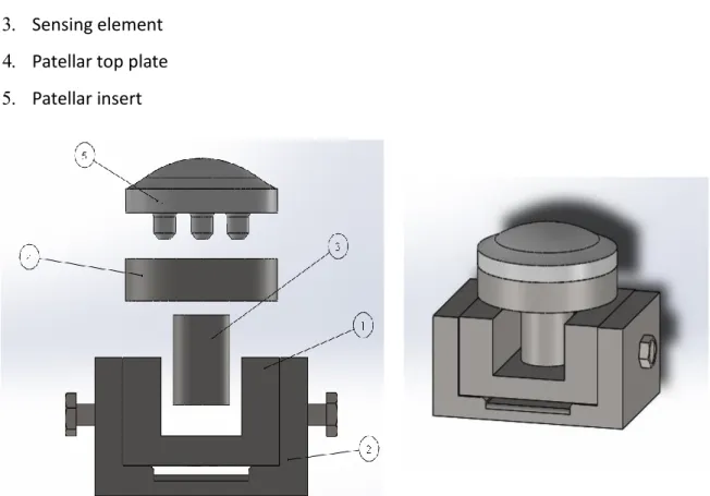
In Fig.28 are shown the components of the instrumented patella: Base support of the load cell
Locking mechanism containing a hole for mounting straps Sensing element
Patellar top plate Patellar insert
Fig. 28: CAD design of the instrumented patella with the polyethylene patellarlinsert (assembly).
plate, making the design customizable.
Furthermore, the sensing element is equal to the tibio-femoral one: in the case of a two-stage separate analysis for the two joints, it is possible to use the same sensing element, easily interchangeable thanks screwing mechanism.
Then, also the load cell calibration can be done only once for both joints, simplifying and speeding the testing procedure of the prostheses.
3.2.2 Position sensing
Before any other possibility, it was considered to use the Tekscan system not only as a pressure sensor for the post-cam engagement, but also as a position sensor in patellofemoral and tibiofemoral joint, because the sensor is already present and usually used in the BEAMS Department.
However, this option was quickly rejected, for the following reasons:
It is too expensive: the aim of the thesis is to develop an inexpensive method to study the internal biomechanics of the prosthesis also in laboratories that do not have such device; It is too fragile: the experimental tests carried out previously in BEAMS Department
revealed that, when subjected to excessive loads on surfaces that are not regular, and that is the case of the knee joints, Tekscan sensor tends to be damaged very easily. This problem can be weakeed by applying a teflon tape that increases its flexibility, but the results are not satisfying;
It's too bulky;
It has its own software for data acquisition: this makes it difficult to synchronize and to combine the position data with force data;
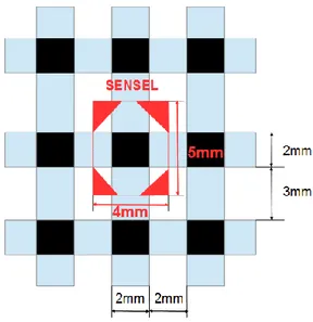
the sensel dimension is about 2x2 mm (Fig.29).
Once excluded the possibility of using the Tekscan, a long research on the market was made, to find a displacement sensor with higher performance and lower price. Inertial, inductive, magnetic, capacitive, piezoelettric, resistive displacement sensors were taken into account but no solution was found: the position sensors commercially available were too much expensive, or fragile, or
with a bad resolution. For this reason, it was decided to manifacture a position sensor in the BEAMS Departiment, with the following specifications: cheap, flexible, non invasive, with an improvable resolution and easily syncronizable with the forces data from load cell.
Fig. 29: Tekscan Mapping sensor datasheet.
Taking a cue from the working principle of resistive touchscreen technology, it has been decided to realize a manifactured bidimensional potentiometer.
Potentiometer is a variable voltage divider with a shaft acting as sliding control for setting the division ratio: this ratio is directly proportional to the position of the shaft, so this instrument is used as displacement sensor. In electronics, a voltage divider (also known as a potential divider) is a passive linear circuit that produces an output voltage (Vout) that is a fraction of its input voltage (Vin). Voltage division is the result of distributing the input voltage among the components of the divider. A simple example of a voltage divider is two resistors connected in series (resistive divider), with the input voltage applied across the resistor pair and the output voltage emerging from the connection between them. If one of the resistance is variable, the voltage divider works as a potentiometer: powering the circuit with an input voltage Vi, the output voltage Vx is inversely proportional to the variable resistor Rx.
The resistance of a given object depends primarily on two factors: what material it is made of, and its geometry. For a given material, the resistance is inversely proportional to its cross-sectional area
and directly proportional to its length. The resistance also depends on the resistivity, characteristic property of each material.
The piezoresistive effect is a change in the electrical resistivity of a material when mechanical strain is applied on it: as pressure increases, the resistance of the material decreases.
Then, by placing a layer of Piezoresistive material between two bodies in contact with each other, the contact point is where the resistance of the material is inferior.
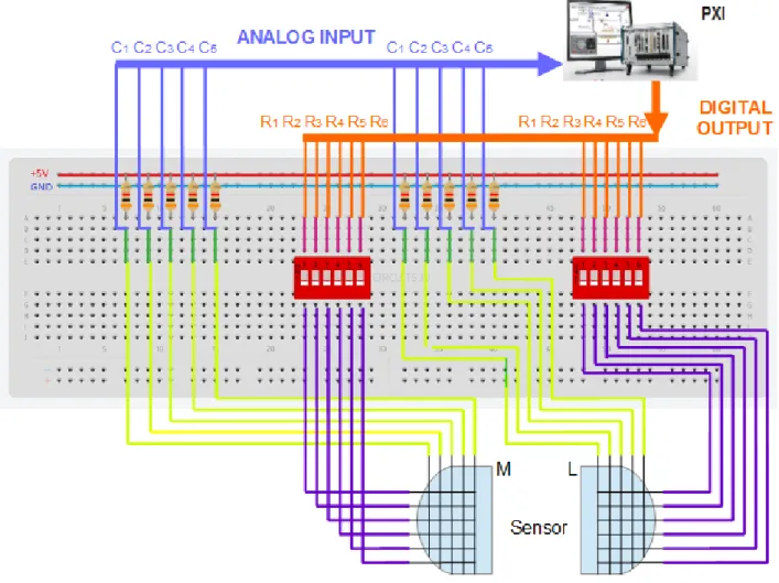
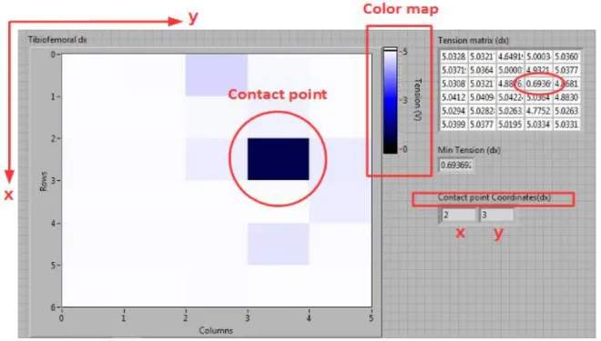
The idea is to create a matrix of voltage dividers in which a Piezoresistive material sheet, inserted into the circuit, acts as a variable resistor Rx. Each element of the matrix, and then each output voltage, is marked by an x-y-coordinate: applying pressure on the matrix, the x-y- coordinate of the application point is where the measured voltage is lower. (Fig. 30)