Student: Jennifer Monclou
Academic Supervisors:
Claudia Marano / Riccardo Gatti
Design School
Milan, Italy
A.Y. 2016 – 2017
Graduation thesis:
MSc. Design and Engineering
A first approach to study the
thermal annealing effect of an object
made of Poly-Lactic Acid (PLA)
produced by Fused Deposition
Modeling (FDM) technology
A first approach to study the thermal annealing effect
of an object made of Poly-lactic Acid (PLA) produced
By Fused Deposition Modeling (FDM) technology
Jennifer Monclou Chaparro
Matricola: 851267
Title to obtain:
MSc. Design and Engineering
L.M. Progetto e Ingegnerizzazione del Prodotto Industriale
Relatore: Claudia Marano
Dipartimento di Chimica, Materiali e Ingegneria Chimica “Giulio Natta” Correlatore: Riccardo Gatti Dipartimento di Design Design School Milan, Italy A.Y. 2016 – 2017
Dame la mano y danzaremos; dame la mano y me amarás. Como una sola flor seremos, como una flor, y nada más... El mismo verso cantaremos, al mismo paso bailarás. Como una espiga ondularemos, como una espiga, y nada más… Gabriela Mistral
A mis padres, mi hermano y los nonos con quienes eternamente andaré.
Contents Contents ... 3 1. Introduction ... 13 1.2 Main goal ... 13 1.3 Methodology ... 13 1.4 Project grounds ... 14 2. Literature Review ... 17 2.1 Additive Manufacturing ... 18 2.1.1 Limitations ... 20 2.1.2 Advantages ... 21 2.2 Desktop-level 3D printers ... 22
2.3 Fused Deposition Modeling (FDM) ... 24
2.3.1 Types of FDM machines ... 25
2.3.2 Software tools ... 25
2.3.3 Printing Parameters ... 28
2.3.4 Poly-Lactic Acid (PLA) filament ... 29
2.4 Open design movement ... 32
2.4.1 e-Nable community ... 33
2.5 Post-processing for objects produced with FDM ... 37
2.5.1 Aesthetic purposes ... 37
2.5.2 Functional purposes ... 38
2.6 Thermal Annealing ... 38
2.6.1 Review of PLA annealing methods ... 39
2.6.2 Review of annealed PLA research ... 44
3. Experiment planning ... 48
3.1 Uniaxial Tensile Test ... 49
3.2 Differential Scanning Calorimetry - DSC ... 49
3.3 Experiment resources ... 50
3.4 Experiment workflow ... 51
4. Experiment execution ... 53
4.1 First run... 54
4.1.3 Collecting the data ... 56
4.1.4 First run findings: dimension variation ... 58
4.2 Second run ... 60
4.2.1 Geometry variation ... 61
4.2.2 Water content variation during the annealing ... 63
4.3 Annealing effect on crystallinity ... 64
4.4 Annealing effect on tensile properties ... 69
4.4.1 Apparent Tensile Modulus ... 69
4.4.2 Apparent Tensile Strength ... 73
4.4.3 Material Brittleness ... 78
4.5 Annealing effect on geometry ... 79
5. Conclusions ... 81
List of figures
Figure 1. Shared knowledge phenomenon ... 14
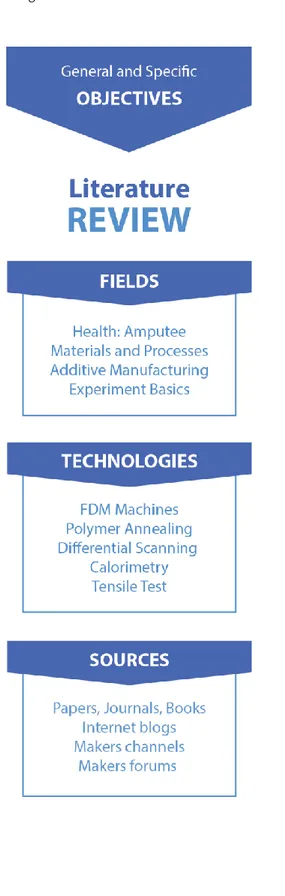
Figure 2. Literature review workflow ... 17
Figure 3. 8 Generic steps for the AM process ... 18
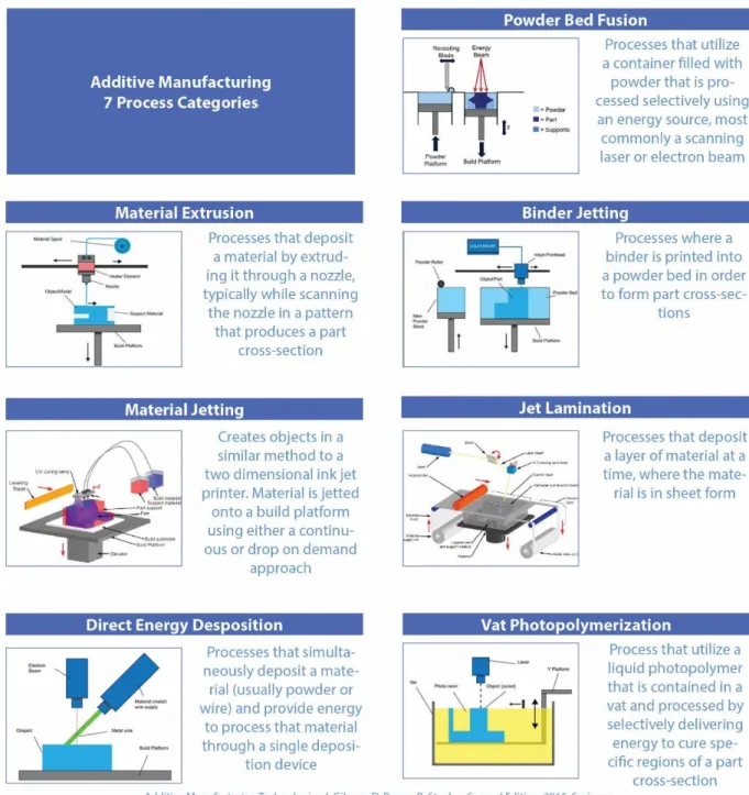
Figure 4. Process categories for AM ... 19
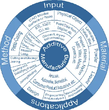
Figure 5. The AM wheel depicting four major aspects of AM ... 20
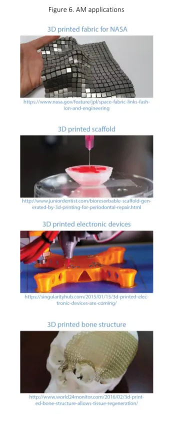
Figure 6. AM applications ... 21
Figure 7. Timeline of 3D printer machines ... 22
Figure 8. The RepRap initiative and MakerBot team ... 23
Figure 9. FDM technology schematic ... 24
Figure 10. Types of FDM machines ... 25
Figure 11. FDM main printing parameters ... 28
Figure 12. Stack of FDM filament ... 29
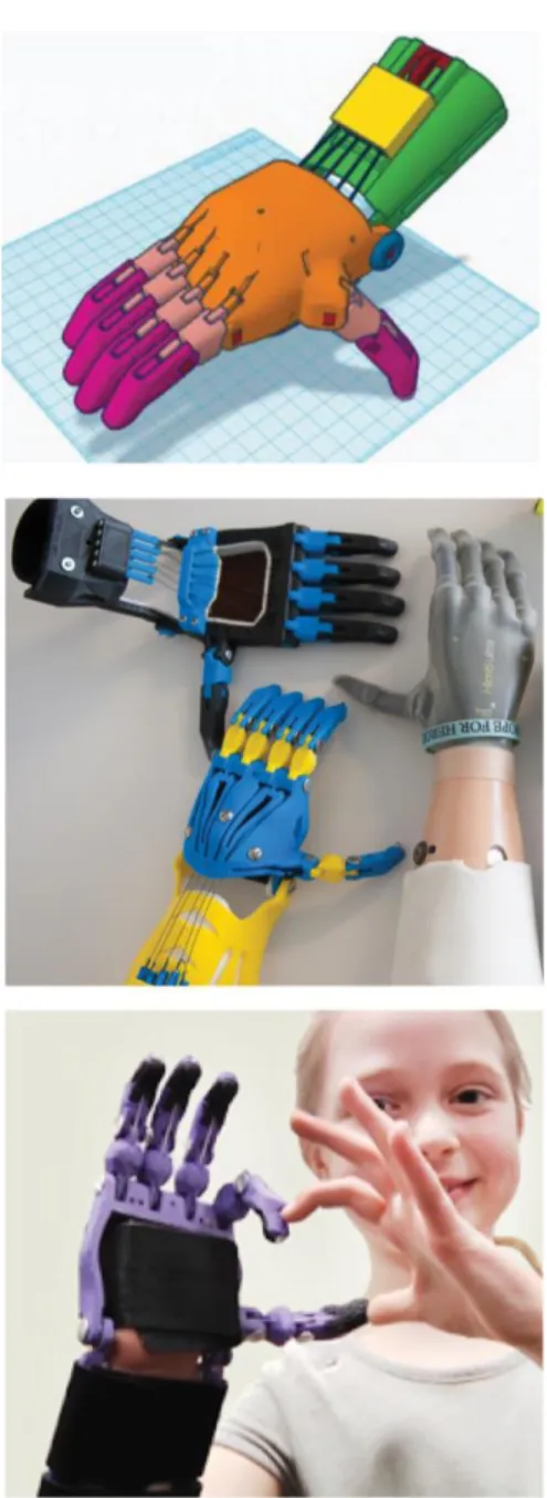
Figure 13. Open Bionics robotic prosthesis ... 32
Figure 14. Robohand and e-Nable community ... 33
Figure 15. e-Nable community ... 34
Figure 16. e-Nable wrist power devices ... 35
Figure 17. Prosthesis using a slot on the gauntlet component ... 35
Figure 18. Gauntlet produced flat-shape wise ... 36
Figure 19. Gauntlet adjusted with Velcro (detail) ... 36
Figure 20. Post-processing for 3D printed objects (aesthetic purposes) ... 37
Figure 21. Post-processing for functional purposes ... 38
Figure 22. Crystallization schematic ... 39
Figure 23. Oven bake method 1 (overview) ... 40
Figure 24. Oven bake method 2 findings ... 41
Figure 25. Boiling water method ... 42
Figure 26. Sous vide method ... 43
Figure 27. Injection moulding annealing findings ... 45
Figure 28. PLA fiber composites findings ... 46
Figure 30. Example of thermogram output from DSC ... 49
Figure 31. Experiment resources ... 50
Figure 32. Workflow of experiment ... 51
Figure 33. Experiment planning ... 53
Figure 34. 20% and 35% infill (triangular infill pattern) ... 54
Figure 35. Measuring with digital image analysis and caliper ... 57
Figure 36. Second run samples ... 60
Figure 37. Setting up the DSC ... 64
Figure 38. Uniaxial tensile test ... 69
Figure 39. Infill percentage variations and infill pattern overview ... 70
Figure 40. Tensile test samples ... 73
Figure 41. Specimen structure scheme (layer-wise distribution) ... 76
Figure 44. Crack typology before and after annealing ... 78
List of tables
Table 1. CAD Software examples ... 26
Table 2. Slicing Software examples ... 27
Table 3.Printer control or “client” software examples ... 27
Table 4. Regular PLA commercial variations ... 30
Table 5. High Temperature PLA commercial offer ... 31
Table 6. PLA-Layer filament datasheet ... 55
Table 7. First run samples ... 56
Table 8. Measurement output with caliper (first run) ... 57
Table 9. Measurement output with digital image analysis (first run) ... 57
Table 10. Comparison of specimen dimension using caliper and digital image analysis (first run)... 58
Table 11. Second run samples (scheme) ... 60
Table 12. Measurement output for specimens without thermal treatment (second run)... 61
Table 13. Caliper measurement output for specimens with thermal treatment (second run) 61 Table 14. Digital image analysis measurement output for specimens with thermal treatment (second run) ... 61
Table 15. Apparent tensile modulus variation ... 71
Table 16. Example of tensile test output ... 74
List of graphs
Graph 1. Geometric variation Caliper vs. Scanner (first run) ... 59
Graph 2. Annealing effect on geometry (second run) ... 62
Graph 3. Weight variation ... 63
Graph 4. First DSC thermogram ... 65
Graph 5. Second DSC thermogram ... 68
Graph 6. Load -Elongation plot ... 72
Graph 7. Apparent Stress-Strain plot ... 72
Graph 8. Stress-Strain plot (as-printed, annealed) ... 75
Graph 9. Apparent tensile modulus for different infill percentage ... 77
Graph 10. Apparent tensile strength for different infill percentage ... 77
List of equations
Equation 1. Water content variation during the annealing ... 63
Equation 2. Areas of melting and crystallization peaks ... 66
Equation 3. Value of areas of melting and crystallization peaks ... 66
Equation 4. Melting heat of PLA before and after annealing ... 66
Equation 5. Degree of crystallinity before and after annealling ... 67
Equation 6. Delta of crystallinity ... 67
GLOSSARY
Additive manufacturing: Refers to a process by which digital 3D design data is used to build up a component in layers by depositing material.
Differential Scanning Calorimetry (DSC): Is a thermoanalytical technique in which the difference in the amount of heat required to increase the temperature of a sample and reference is measured as a function of temperature.
Fused Deposition Modeling (FDM): Is a molten material system, characterized by a pre-heating chamber that raises the material temperature to melting point so that it can flow through a delivery system. Fused Deposition Modeling extrudes the material through a nozzle in a controlled manner.
Modulus of elasticity (E): Indicates the relationship between stress and strain in the deformation of a solid body. It defines the ratio of the stress applied to a body and the resulting increased strain result without influencing the cross-sectional deformation of the test body.
Poly-Lactic Acid (PLA): Is a biodegradable and bioactive thermoplastic aliphatic polyester derived from renewable resources, such as corn starch, cassava roots, starch or sugarcane, is one of the two most commonly used desktop 3D printing filaments.
Polymers: Is a large molecule, or macromolecule composed of many repeated subunits. The majority of manufactured polymers are thermoplastic. This property allows for easy
processing and facilitates recycling.
Prosumer: Is part of an emerging dialogue about how technology serves people. While the consumer is often a passive recipient of technology, a prosumer may help to shape the use of technologies or otherwise get involved in the products and services provided to them,
because that individual has a certain professional role in the process.
Tensile strength at yield: Is the tensile stress level at which the rise in the stress-strain curve equals zero for the first time.
Thermal annealing: Commonly used for metals but lately also being used for a postprocessing treatment of polymers which consists of submitting a sample to a controlled temperature for a limited time.
Thermal transition: The changes that take place in a polymer when its heated. The melting of a crystalline polymer and the glass transition are examples of thermal transition.
ABSTRACT
Additive Manufacturing (AM) development is gaining momentum growing both at a high and low end, the first one involves expensive high-powered energy sources and complex scanning algorithms where the produced parts features material properties that are equivalent to their traditionally manufactured counterparts. At the low end there can be found desktop-scale 3D printers which are eliminating cost barriers and resulting in a sort of democratized
manufacturing where enthusiast users also called prosumers or makers are now able to interact with a technology that, in the past, was relegated to large manufacturing firms. Fused Deposition Modeling (FDM) is one of the most popular desktop-scale 3D printers due to low cost of the machines without sacrificing quality, the large variety of filaments available on the market that allows to reach different purposes, the relatively small size of the
machines, their efficiency and user-friendly interaction.
The opportunity for this project relays on the popularization of desktop-level AM technology resulting in a culture of “Do it Yourself” and a growing community driven by shared
knowledge. Where it is revealed the opportunity of contributing with an international community of volunteers that design and develop prosthesis for children from low income resources families. In this way the project focuses on the understanding of potential post-processes based on the FDM technology.
For the experiment it was carried out a Differential Scanning Calorimetry and uniaxial mechanical test with the purpose of assessing the mechanical properties and thermal annealing effect on the object made of PLA produced by FDM technology.
Key words: annealing, tensile test, differential scanning calorimetry, fused deposition modeling, prosthesis, Poly-lactic Acid, semi-crystalline polymer.
RIASSUNTO
Lo sviluppo della produzione baste sull`Additive Manufacturing (AM) è in crescita sia al livello altamente professionale sia a quello più artigianale, il ambito professionale riguarda al uso di macchine che hanno bisogno di risorse energetiche elevate e utilizzano algoritmi complessi ma che alla fine forniscono prestazioni simili a quelle di prodotti ottenuti con i processi di manifattura tradizionale. Al livello meno professionale si trovano delle stampanti 3D progettate per piccoli spazi di lavoro che stanno anche eliminando barriere di costo. In questo caso si tratte di una produzione democratizzata dove gli utenti appassionati qualche volta chiamati “prosumer”, sono ora in grado di interagire con una tecnologia che, in passato, è stata relegata a grandi aziende di progettazione e produzione.
Fused Deposition Modeling (FDM) è uno dei più popolari processi di stampa 3D desktop grazie a basso costo delle macchine senza sacrificare la qualità, grande varietà di filamenti disponibili sul mercato che consente di raggiungere diversi scopi, dimensioni relativamente ridotte delle macchine, efficienza e interazione user-friendly.
L'opportunità di questo progetto si basa sulla divulgazione della tecnologia di produzione additiva a livello desktop, che si traduce in una cultura di "Fai da te" è in una comunità in crescita guidata da conoscenze condivise. Dove si scopre la opportunità di contribuire con una comunità internazionale di volontari che progettano e sviluppano protesi per bambini da famiglie a basso reddito. In questo il progetto si concentra sulla comprensione di potenziali processi di post-elaborazione basato su un prodotto fatto con la tecnologia FDM.
Sono estate condotti misure di calorimetria differenziale a scansione e prove meccanica di trazione uniassiale a lo scopo di valutare l’effetto di una ricottura sulla struttura de un oggetto fatto da acido polilattico (PLA per il suo acronimo in inglese) e le sue proprietà meccaniche.
Parole chiave: ricottura, test di trazione, scansione differenziale di calorimetria, produzione additiva, protesi, acido polilattico, polimero semicristallino.
1. Introduction
The project starts inside the university classroom as part of the Master Degree in Design & Engineering, programme that results from the cooperation of three faculties from Politecnico di Milano: Design, Mechanical Engineering and Material Engineering and Nanotechnology; along with two professors from Politecnico di Milano, one from the design department with a background on desktop-level additive manufacturing and the other from the material
engineer department with a vast experience in polymeric materials and experimental analysis; was made the choice of applying additive manufacturing with an experimental approach.
The opportunity for this project relays on the popularization of desktop-level additive manufacturing (AM) technology resulting in a culture of “Do it Yourself” and a growing community driven by shared knowledge. Where it is revealed the opportunity of contributing with an international community of volunteers that design and develops prosthesis for children from low income resources families. In this way the project focuses on the understanding of potential post-processes based on the FDM technology.
1.2 Main goal
The main goal of the project is to study the thermal annealing effect of an object made of Poly-Lactic Acid (PLA) produced by Fused Deposition Modeling (FDM) technology.
1.3 Methodology
Once the main goal is defined the following workflow will allow to achieve it.
1. Definition of an experiment taking information from two main sources, the prosumer community and scientific journals.
2. Set a preliminary test to define the sample test geometry and main testing conditions. 3. Study the effect of thermal annealing on the crystallinity degree of a PLA object
produced by FDM technology.
4. Study the effect of thermal annealing on the apparent modulus and tensile strength of a PLA object produced by FDM technology.
1.4 Project grounds
The 3D printing revolution is occurring both a high end and a low end. One end of the technology spectrum involves expensive high-powered energy sources and complex scanning algorithms. The other end is focused on reducing the complexity and cost of a well-established AM process to bring the technology to the masses. Major advances will continue to be made both at the high end with direct metal processes that aim for end-use products as the most noticeable example; at low end with the desktop-level machines that will continue to improve while the cost declines. This 3D printing revolution has been fed by the idea of sharing as many
technical aspects as possible, this revolution has been growing thanks to the creation of online communities that were rapidly feed by
enthusiasts from all around the world and went beyond the technicalities by exploring more capabilities and applications on their daily lives. This community is being called in different ways: thinkers, makers or prosumers, terms that come from the “do it yourself” (DIY) culture. Along with the 3D printing revolution many individuals are now involved in this culture, phenomenon that can be seen from the way digital platforms are used. Several YouTube channels feature some of the most informative and entertaining content about 3D printing, addressing subjects such as 3D printing tutorials, tips and tricks or product reviews. The major players up until now are: Thomas Sanladerer (117.600 subscribers), 3D Printing Nerd (151.400), Maker`s Muse (203.500), I Like to Make Stuff (1’491.000 subscribers) and many more who continue little by little setting a solid path towards the idea of shared knowledge.
Other common platforms for the diffusion of 3D printing culture are the ones that act as a 3D model repository, being “thingiverse.com” the most popular, but with over 20 new websites currently available ready to offer as much “things” to print as possible.
But none of these 3D models can be created without a software tool which can be found from completely open-source to licensed products. Users can now use their Computed Aided Design (CAD) skills with open-source software such as FreeCAD or LibreCAD or even use systems where the users can interact via a web browser or their mobile phone apps like Thinkercad or Onshape.
One particular community that has taken the best of shared knowledge, DIY culture and 3D print all together with a strong social awareness is “e-Nable” a network of volunteers that design and produce human prosthesis using 3D printing. They support the maker movement by bringing together designers, engineers, physicians, 3D print enthusiasts, families and amputees, to create, innovate, re-design and share 3D-printable prosthetics. This global community of volunteers who are donating their time, talent and resources is able to do so thanks to the accessibility of 3D models repositories, forums, instructional videos, manuals, etc. Thus allowing them to produce open-source, low cost prosthetic devices using Fused Deposition Modeling (FDM) technology which is one the most popular desktop-level 3D printers giving the low cost and small size of the machines, variety of filaments found the market, efficiency and user-friendly interaction.
Giving the great diffusion of this initiative there are different prosthesis shapes, post processing alternatives or methods of assembly. This project is focused on the potential capabilities of thermal annealing post-process to improve the material mechanical behaviour. This process usually apply to metals, is also successfully used on semi-crystalline polymers. Thermal annealing is a post-process commonly used on injection-moulded polymer-based components in order to enhance the materials tensile and impact strength. There are several researches reporting the effect of thermal annealing on the polymer structure and its
mechanical behaviour, but few ones about the annealing effects for 3D printed components. Thus arise an opportunity for studying how to improve certain mechanical behaviour for an object produced by the same technology this prosthesis are produced. Since the goal of “e-Nable” community is to reach as many volunteers as possible and let them create these devices on their own, why not let them enlarge their knowledge by showing the effect of a particular post-process that might extend the prosthetics service life?
LITERATURE
REVIEW
Additive Manufacturing Desktop-level 3D Printers Fused Deposition Modeling (FDM)
Open Design Movement Post-processing for FDM
2. Literature Review
A literature review is a text of a scholarly paper, on the current knowledge about a particular topic including substantive findings, as well as theoretical and methodological contributions. Literature reviews are secondary sources, and do not report new or original experimental work and are a basis for research in nearly every academic field. [1]
For the development of this project there was used a systematic approach in order to gather information regarding field, technology and sources of interest and having as a base the general and specific objectives already listed in the previous chapter.
It is important to understand about all the relevant fields included in the project: FDM machines and its diverse filaments, thermal treatment for polymer, Poly-Lactic Acid (PLA) filament, open source prosthetics movement, material post-processing, direct scanning calorimetry (DSC) and material crystallization. See list on Figure 2.
1. http://www.academicwritingtutor.com/uses-analysis-rhetorical-analysis-article-analysis-literature-review/
2.1 Additive Manufacturing
Additive manufacturing is the formalized term for what used to be called rapid prototyping and what is popularly called 3D Printing. AM is a group of emerging technologies that create objects from the bottom-up by adding material. The AM process begins with a 3D model of the object, usually created by computer-aided design (CAD) software or a scan of an existing artifact.
Specialized software slices this model into cross-sectional layers, creating a computer file that is sent to the AM machine. The AM machine then creates the object by forming each layer via the selective placement (or forming) of material. [2]
There are different stages of the AM process that can be summarise in eight generic steps (Figure 3) and can be classified in seven process categories (Figure 4).
2. Additive Manufacturing Technologies. Ian Gibson, David Rosen, Brent Stucker. Second Edition 2015, Springer
Figure 3. 8 Generic steps for the AM process
Fundamentally, the development of AM can be described in four primary areas. The additive manufacturing wheel in Figure 5 depicts these four key aspects of additive manufacturing. [3]
Figure 5. The AM wheel depicting four major aspects of AM
Input: Electronic information requires to describe the object in 3D. There are two possible starting points – a computer or a physical model.
Method: While there are more than 40 vendors for AM systems, the method employed can be classified as it shown on the figure 5.
Material: The material can come in solid or liquid.
Applications: Most of the AM parts are finished or touched up before they are used for their intended applications.
2.1.1 Limitations
• Limited for mass production purposes.
On average, AM processes are capable of creating a 1.5 inch cube in about an hour. Whereas an injection molding machine is capable of making several similar parts in less than a minute. This AM process limitation is valid only for the production of several thousand of a product, since tooling must be created for each part one wishes to produce by injection molding.
• Need for better materials.
Most AM processes use plastic materials that are not well characterized, and the
performance of the relevant products are lower traditionally manufactured counterparts. Further, in some AM processes, part strength is not uniform—due to the layer-by-layer fabrication process, parts are often weaker in the direction of the building.
2.1.2 Advantages
The benefits of AM systems are immense and can be broadly categorised into direct and indirect ones.
• Direct benefits
Possibility to experiment with physical models of any complexity in relatively short time.
Increased part complexity that cannot be produced by any other means.
The manufacturer can reduce the labour content of manufacturing, since part-specific setting up and programming are eliminated, machining or casting labour is reduced, and inspection and assembly are minimised as well reducing material waste. • Indirect benefits
Reduced time-to-market, resulting in reduced risk as there is no need to project customer needs and market dynamics several years into the future.
Increasing the diversity product offerings and pursue market niches which are too small to justify due to tooling cost (including custom and semi-custom production). Large availability of products more closely suited consumer needs. Firstly, the is a much greater diversity of offerings to choose from. Secondly, one can buy (and even contribute to the design of) affordable built-to-order products. [4]
4.https://3dprintingindustry.com/3d-printing-basics-free-beginners-guide/history/
2.2 Desktop-level 3D printers
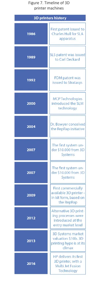
Before talking about desktop-level 3D printers is important to take a look to the history of this technology and see for example how the expiration of older patents has led to an explosion of development of an array of low-cost personal 3D printers.
This technology dates back to the 80`s with the first patent issued to Charles Hull for
stereolithography apparatus who will lately found one of the largest and most prolific organizations operating in the 3D printing sector today: 3D Systems Corporation.
Throughout the 1990’s and early 2000’s a host of new technologies continued to be
introduced, still focused wholly on industrial applications and while they were still largely processes for prototyping applications. During the mid-90`s, the sector started to show signs of distinct diversification with two specific areas of emphasis that are much more clearly defined today. First, there was the high end of 3D printing, still very expensive systems, which were geared towards part production for high value, highly engineered, complex parts. This is still ongoing, but the results are only now really starting to become visible in production applications across the aerospace, automotive, medical and fine jewellery sectors, as years of R&D and qualification are now paying off. A great deal still remains behind closed doors and/or under non-disclosure agreements (NDA). [5]
5. https://www.researchgate.net/publication/289522663_3D_Printing_Pharmaceutical_Manufacturing_Opportunities_and_Challenges
Figure 7. Timeline of 3D printer machines
At the other end of the spectrum, some of the 3D printing system manufacturers were developing and advancing ‘concept modellers’, as they were called at the time. Specifically, these were 3D printers that kept the focus on improving concept
development and functional prototyping, that were being
developed specifically as office- and user-friendly, cost-effective systems. The prelude to today’s desktop machines.
But it wasn’t until January 2009, when the patent of the FDM technology expired, that the first commercially available 3D printer was offered for sale, it was the RepRap kit. This project started in England in the University of Bath and consist on developing a low-cost 3D printer that can print most of its own components, but now is made up of hundreds of collaborators
worldwide. MakerBot company -based on New York City- builds on the early progress of the RepRap project which aimed to help the open-source 3D printer movement. [6]
The idea of sharing any technical aspect regarding how to design the machine, how to build and operate it, how to fix it or improve several
aspects, growth thanks to the creation of online communities that were rapidly feed by enthusiasts from all around the world.
6. "Reprap the replicating rapid prototyper". Jones, R.; Haufe, P.; Sells, E.; Iravani, P.; Olliver, V.; Palmer, C.; Bowyer, A. (2011)
2.3 Fused Deposition Modeling (FDM)
Objects created with an FDM printer start out as computer-aided design (CAD) files. Before an object can be printed, its CAD file must be converted to a format that a 3D printer can understand — usually .STL format. FDM printers use two kinds of materials, a modeling material, which constitutes the finished object, and a support material, which acts as a scaffolding to support the object as it's being printed.
During printing, these materials take the form of plastic threads, or filaments, which are unwound from a coil and fed through an extrusion nozzle. The nozzle melts the filaments and extrudes them onto a base, sometimes called a build platform or table. Both the nozzle and the base are controlled by a computer that translates the dimensions of an object into X, Y and Z coordinates for the nozzle and base to follow during printing.
In a typical FDM system, the extrusion nozzle moves over the build platform horizontally and vertically, "drawing" a cross section of an object onto the platform. This thin layer of plastic cools and hardens, immediately binding to the layer beneath it. Once a layer is completed, the base is lowered to make room for the next layer of plastic. [7]
Figure 9. FDM technology schematic
https://www.additively.com/en/learn-about/fused-deposition-modeling
2.3.1 Types of FDM machines
Since 2009 when there was commercially available a desktop 3D printer, designers, makers, thinkers and hobbyists have developed different variations for the molten filament
technology, resulting on an offer of some variations. The principle of this machines is the movement whether the nozzle or the printing bed on the X, Y and Z axis, in this way there can be founded cartesian, delta, polar or SCARA (Figure 10).
Figure 10. Types of FDM machines
2.3.2 Software tools
There can be said that there are four steps on the path from concept to printed object: the idea, the digital model, the tool path, and the final print and three layers of software – CAD, CAM, and “client” – bridge the gaps.
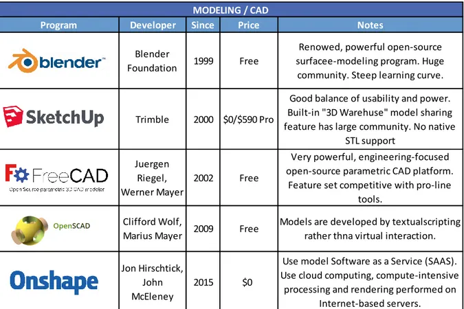
• Computer Aided Design (CAD) Software: Even if the model is scanned from a real object, the user might want to adjust in a CAD program. There are many file formats for 3D models, but almost all 3D printing CAM software expects STL. Unfortunately, not all STL files are printable.
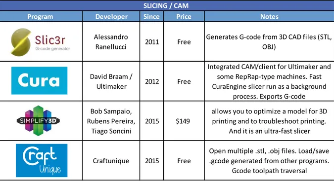
• Slicer software: “Slicing” programs translate 3D models into physical instructions for the printing robot, which can be visualized as a tangle of “tool paths” the print head will follow to fill in the model`s shape, using the most common output industry-standard G-code files.
• Printer Control / Client: Is the printer`s control panel. It sends CAM instructions and
provides an interface to control printer functions. As CAM and client programs advance,
they are increasingly being combined into single-interface printing environments. [8]
Table 1. CAD Software examples
Make magazine, special issue: 3D printer buyer´s guide 2014
Program Developer Since Price Notes
Blender
Foundation 1999 Free
Renowed, powerful open-source surfacee-modeling program. Huge
community. Steep learning curve.
Trimble 2000 $0/$590 Pro
Good balance of usability and power. Built-in "3D Warehuse" model sharing feature has large community. No native
STL support Juergen
Riegel, Werner Mayer
2002 Free
Very powerful, engineering-focused open-source parametric CAD platform.
Feature set competitive with pro-line tools.
Clifford Wolf,
Marius Mayer 2009 Free
Models are developed by textualscripting rather thna virtual interaction. Jon Hirschtick,
John McEleney
2015 $0
Use model Software as a Service (SAAS). Use cloud computing, compute-intensive
processing and rendering performed on Internet-based servers.
Table 2. Slicing Software examples
Make magazine, special issue: 3D printer buyer´s guide 2014
Table 3.Printer control or “client” software examples
Make magazine, special issue: 3D printer buyer´s guide 2014
8. Make magazine, special issue: 3D printer buyer´s guide 2014
Program Developer Since Price Notes
Alessandro
Ranellucci 2011 Free
Generates G-code from 3D CAD files (STL, OBJ)
David Braam /
Ultimaker 2012 Free
Integrated CAM/client for Ultimaker and some RepRap-type machines. Fast CuraEngine slicer run as a background
process. Exports G-code Bob Sampaio,
Rubens Pereira, Tiago Soncini
2015 $149
allows you to optimize a model for 3D printing and to troubleshoot printing.
And it is an ultra-fast slicer
Craftunique 2015 Free
Open multiple .stl, .obj files. Load/save .gcode generated from other programs.
Gcode toolpath traversal
SLICING / CAM
Program Developer Since Price Notes
ReplicatorG MakerBot 2008 Free Original MakerBot printer client.Largely
superseded by MakerWare
Repetier-Host Kliment Yanev 2011 Free
Best know of three utilities in popular "Printum" suite. Requires Phyton. Fiddly
installation
Octoprint Gina Hausse 2011 Free
Web-based printer interface offering "anywhere" control, monitoring, and
G-code visualization.
Afinia 3D Afinia 2012 $0 Integrated CAM/client for Afinia/Up
printers. No export
2.3.3 Printing Parameters
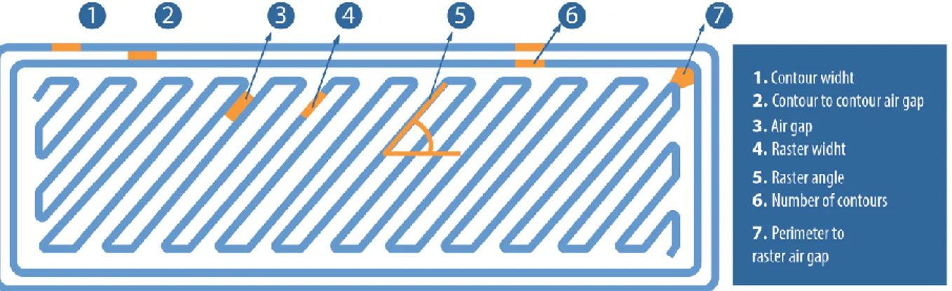
The majority of FDM 3D printed parts are not printed solid. Printing solid parts requires high amounts of material and long print time resulting in high costs. To optimise the printing process most parts are printed with solid shells and filled with infill. Shells and infill play an important role on the quality, appearance and function of FDM printed parts. [9] Other parameters can be edited depending on the “slicer” software capabilities, Figure 11 depicts seven of the most common parameters available for editing.
1. Contour width: refers to the width of the molten filament depositing
2. Contour to contour air gap: after the molten filament run is finish and the next run is about to start there can se set an air gap which can be adjusted smaller or larger 3. Air gap: the space between two deposited filaments
4. Raster width: can be adjusted smaller or larger is the result of a combination of nozzle and filament diameter, printing speed and molten material extrusion speed
5. Raster angle: is the angle in which the selected pattern will be deposited 6. Number of contours: defined also as the shell or wall thickness
7. Perimeter to raster air gap: is the gap between the deposited filament from the raster that is forming a pattern as an infill process and the perimeter of the object
Figure 11. FDM main printing parameters
2.3.4 Poly-Lactic Acid (PLA) filament
Figure 12. Stack of FDM filament
http://3dinsider.com/abs-vs-pla-shootout/
Another vital element of the FDM technique is the use of a spool of polymeric filament that will be heated by a resistor on the nozzle and pulled down via a stepper motor. Plenty of materials are currently used with different temperature ranges, degree of recyclability, mechanical and chemical properties, colors, prices.
Acrylonitrile Butadiene Styrene (ABS) and Poly(lactic acid) (PLA) are the go-to plastics for most consumer-grade 3D printers. New types of plastic, blends of plastics with various additives, and grades of plastic formulated specifically for 3D printing are appearing all the time. With simple tools it´s even possible to turn pellets or other plastic scrap into usable filament right in the users office. [10]
PLA (Polylactic Acid) is one of the two most commonly used desktop 3D printing filaments. It is the "default" recommended material for many desktop 3D printers. PLA is useful in a broad range of printing applications, has the virtue of being both odorless and low-warp, and does not require a heated bed. PLA filament is made from annually renewable resources (corn-starch) and requires less energy to process compared to traditional (petroleum-based) plastics. Outside of 3D printing, PLA plastic is often used in food containers, such as candy wrappers, and biodegradable medical implants, such as sutures. [11]
Since there are different types of PLA, in Table 4 and Table are briefly described both for regular PLA and High Temperature, some specifications for the commercial filaments and their capabilities.
10. Make magazine, special issue: 3D printer buyer´s guide 2014 guide 2014 11.https://www.matterhackers.com/3d-printer-filament-compare
Table 4. Regular PLA commercial variations
https://filaments.ca/pages/temperature-guide#cfpla
Name Print temp. - speed Comments
PLA (Original &
Creative Series) 215°C - 235°C
Can be printed both with and without a heated print bed. Heated print: recommended to set temperature to: 60°C - 80°C
First layer usually 5°C - 10°C higher than subsequent layers. Glow in the dark use 5°C - 10°C higher.
Sticks well to Blue painter's tape. Sticks well to extra strong hair spray.
Soft PLA 210°C - 220°C
Print slow. Reccomended print speed:10 - 20mm/s.
Reduce retraction. Build plate, recommended: blue masking tape with a thin layer of glue stick on top.
Print bed temperature to approximately 60°C - 100°C. Direct feed printer recommended.
Use a bit of lubricant (like WD40) for bowden tube, although bowden extruders are not ideal for printing flexible filaments.
Make sure filament is clean (free from hand grease). Performs best in printers with direct-drive extruders.
Thermochrome
PLA Aprox. 210°C
Follow same recommendations as regular PLA.
If printed part is < 29°C it will have an opaque anthracite Grey color. If printed part is > 29°C it will have a translucent / White color.
EasyFil 2.85mm
PLA 210°C - 220°C
Can be printed both with and without a heated print bed. Heated print: recommended to set temperature to: 35°C - 60°C.
Sticks well to blue masking tape and extra strong hairspray Print speed: 40 - 80 mm/s
Carbon Fiber
Reinforced PLA 190°C - 230°C
Processing is comparable to standard PLA. No heated bed required.
Due to increased brittleness, process may be less consistent on smaller nozzles and/or bowden type machines.
Nozzle size: 0.35mm - 0.5mm
High Temperature
PLA 190°C - 230°C
Processing is comparable to standard PLA.
No heated bed required, though a heated bed may help crystallize the material after printing and make oven soaking unnecessary for some parts.
Nozzle size: 0.25mm - 0.5mm
Good results achieved when printing using a .5mm nozzle and direct-drive spring loaded pinch-roll style extrusion head. Layer adhesion was excellent and warpage was low.
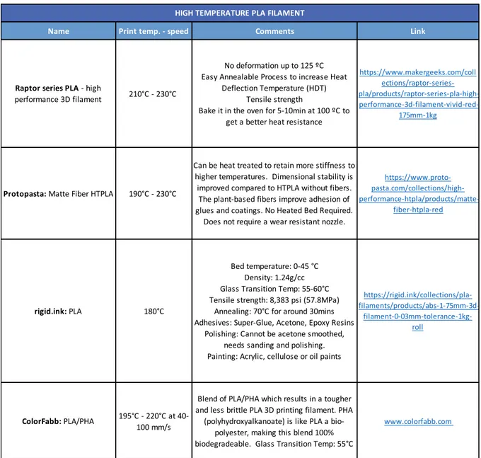
Table 5. High Temperature PLA commercial offer
Name Print temp. - speed Comments Link
Raptor series PLA - high
performance 3D filament 210°C - 230°C
No deformation up to 125 ºC Easy Annealable Process to increase Heat
Deflection Temperature (HDT) Tensile strength
Bake it in the oven for 5-10min at 100 ºC to get a better heat resistance
https://www.makergeeks.com/coll ections/raptor-series- pla/products/raptor-series-pla-high-
performance-3d-filament-vivid-red-175mm-1kg
Protopasta: Matte Fiber HTPLA 190°C - 230°C
Can be heat treated to retain more stiffness to higher temperatures. Dimensional stability is improved compared to HTPLA without fibers. The plant-based fibers improve adhesion of glues and coatings. No Heated Bed Required.
Does not require a wear resistant nozzle.
https://www.proto- pasta.com/collections/high- performance-htpla/products/matte-fiber-htpla-red rigid.ink: PLA 180°C Bed temperature: 0-45 °C Density: 1.24g/cc Glass Transition Temp: 55-60°C Tensile strength: 8,383 psi (57.8MPa)
Annealing: 70°C for around 30mins Adhesives: Super-Glue, Acetone, Epoxy Resins
Polishing: Cannot be acetone smoothed, needs sanding and polishing. Painting: Acrylic, cellulose or oil paints
https://rigid.ink/collections/pla- filaments/products/abs-1-75mm-3d- filament-0-03mm-tolerance-1kg-roll ColorFabb: PLA/PHA 195°C - 220°C at 40-100 mm/s
Blend of PLA/PHA which results in a tougher and less brittle PLA 3D printing filament. PHA
(polyhydroxyalkanoate) is like PLA a bio-polyester, making this blend 100% biodegradeable. Glass Transition Temp: 55°C
www.colorfabb.com
2.4 Open design movement
There are several terms related with a global
knowledge sharing that have being gather throughout the years: open design, open-source software and hardware, open collaboration, free software, etc; all of them aiming for a common goal which is to develop physical products, machines, software and/or systems through use of publicly shared design information. [12] The open-design movement currently unites two trends. On one hand, people apply their skills and time on projects for the common good, perhaps where funding or commercial interest is lacking, for
developing countries or to help spread ecological or cheaper technologies. On the other hand, open design may provide a framework for developing advanced projects and technologies that might be beyond the resource of any single company or country and involve people who, without the copyleft mechanism, might not collaborate otherwise.
Nowadays there are different open source projects regarding 3D printed prosthesis.
• e-Nable: A global network of volunteers using 3d printing to give the world a "helping hand." Website: http://enablingthefuture.org
• Open Biomedical initiative: A global non-profit initiative created to support the traditional biomedical field and focused to collaboratively design, develop and distribute open source 3D printable health and accessibility supports Website: http://www.openbiomedical.org/ • Open Bionics: Create affordable bionic hands for
amputees, researchers or hobbysts. Website: https://www.openbionics.com
12. https://en.wikipedia.org/wiki/Open_design
Figure 13. Open Bionics robotic prosthesis
2.4.1 e-Nable community
Is a network of passionate volunteers using 3D printing to give the World a "Helping Hand.” They support the Maker Movement in mechanical hands by bringing together designers, engineers, physicians, 3D print enthusiasts, families and amputees, to create, innovate, re-design and share 3D-printable prosthetics.
This project started between a professor from Rochester Institute of Technology and a South African carpenter who lost some of his fingers on a shop accident. After professor Schull saw the story of a carpenter who accidentally cut off his fingers on a workshop and then was told that partial hand prosthetics are really
expensive and hard to come by, he decided to find a solution by himself. He went to google and found his way to Ivan Owen a puppet and prophet maker based in Washington state who had made a big mechanical hand controlled by fingers as a prophet for a movie. Together they worked for over a year designing the hand and eventually come upon a way of 3D printing this device, they recognized that this device will be helpful not just to people who chopped of their fingers but also for people with congenital syndromes, so they make the design available online.
At this point professor Schull found this initiative and decided to give it a push and ask from makers all over the world -via youtube comments- to develop these devices and share them to those in need. Little by little hundreds of volunteers with 3D pritners started to appear on a network managed by Prof. Schull, in this way if a kid needs to access a hand prosthesis his family should simply check Prof. Schull map and find someone near them who can make it. [13]
Statistics state that 1 in 1500 children are born missing fingers or hands and there are many around the world who lose them due to war, disaster or disease. Because children grow so quickly, there are few prosthetic devices available to them and those that are available – can cost thousands of dollars and many families in the world cannot afford them.
Now thanks to 3D printing and e-NABLE, children as young as 3 years old who are missing fingers or hands, are able to obtain devices that will allow them to do things many people take for granted. This community has another goal that consists in teaching families how to create these devices on their own, in this way the more this knowledge is spread, the more hands can be created. To date, e-Nable community have created nearly 2000 free “body
powered” 3D printed devices in over 40 countries and the numbers grow daily. Those prosthesis are not only growing on numbers but also on diversity, as more designers and engineers join the community the types of devices are getting substantial variations in order to cover more medical pathologies.
13. https://www.youtube.com/watch?v=XQ8tPOqN7WE
2.4.1.1 Weak points of 3D printable prosthesis
One of the main features of the wrist power (Figure 16) prosthesis from e-Nable is the attachment to the kid arm, the gauntlet count with a couple of slots on which a Velcro strap is adjusted. Unfortunately this slot (a very common solution for attaching the prosthesis to the missing limb as seen on Figure 17) represents a weak point because is a feature the user is constantly adjusting. As a result, the maker community has given solutions such as: printing the gauntlet completely flat and later on thermoforming it by submerging the desirable area to fold (Figure 18).
Figure 16. e-Nable wrist power devices
http://enablingthefuture.org/wrist-powered/
Figure 18. Gauntlet produced flat-shape wise
https://www.youtube.com/watch?v=BihhKHjguZY
2.5 Post-processing for objects produced with FDM
Since 2009 when there was commercially available a desktop 3D printer, designers, makers, thinkers and hobbyists have explored not different configurations for the FDM machines and also the filaments which has an application spectrum ranging from aesthetic to functional. There has been produced filaments infused with carbon nanotubes or glass fibers with the aim of strengthening the manufactured component, there are also transparent filaments, elastic, biodegradable or designed to withstand high temperatures.
With the evolution of filament and the development of post-processing techniques for the objects obtained with FDM technology has come hand-in-hand with same parity of purposes: aesthetic or functional. Depending on the type of filament there can be done basic post-processing like: sanding, polishing, coating, painting or some more complex ones like, metal plating, vapor smoothing, dipping or annealing.
2.5.1 Aesthetic purposes
FDM parts often depend on aesthetics or appearance making post processing an important stage in the production of FDM parts.
Figure 20. Post-processing for 3D printed objects (aesthetic purposes)
2.5.2 Functional purposes
A persistent issue with 3D printed parts is strength and durability, they are not as strong as injection molded parts, nevertheless giving the evolution of this technology towards domestic use and a sort of democratization many people are now using 3D printed parts in production scenarios, mainly due to various techniques for strengthening parts.
Figure 21. Post-processing for functional purposes
2.6 Thermal Annealing
Originally used in metallurgy to increase the strength of metal objects. Annealing is one of several “heat treatments” that are used to change the physical properties of metal without changing the metal’s existing shape. [14]
The fundamentals of the annealing process have been adapted to the plastics field. In the plastics industry, annealing is the process of heating a plastic part up to half the polymer melting temperature for a moderate period before cooling it down to room temperature. Fused Deposition Modeling (FDM) involves heating the printing material so that it can be extruded. Once extruded, the material then cools to form the printed object. Plastic is a fairly poor conductor of heat. This means that heated plastic tends to cool unevenly. This uneven cooling introduces stress into a printed object.
Typically, with any material internal defects are evident and create internal stresses which weaken its overall strength. To minimize the effect of these grains, annealing can be done to soften the material, relax the grain structures causing the internal
stresses, and allow new, strain-free grains to form as replacements.
At microscopic level, the structure of the plastic is unorganised and rather amorphous. Heating the plastic, extruding and cooling it reorganizes this structure into a more organised crystalline form. These crystals tend to be large, broadly similar to those that exist in metal after initial heating and cooling. [15]
Also, when the polymer approaches or reaches its glass transition temperature, the molecular chains have enough energy to enter into a rubber
amorphous state. In this state, they are able to rotate, move, stretch, etc. This releases some of the tensile and compression forces that resulted from uneven cooling. Both of these things, in turn, makes the plastic stronger, stiffer and more resistant to the stresses that cause failure.
2.6.1 Review of PLA annealing methods
Current methods for annealing 3D printed
components can be found mostly on makers digital platforms (patreon.com, makerweeks.com), video-sharing websites (youtube.com), development digital platforms (GitHub), and other platforms with
contents of interest for the desktop 3D print community (rigid.ink, all3dp.com).
15. https://rigid.ink/blogs/news/how-to-anneal-your-3d-prints-for-strength
2.6.1.1 Oven bake method 1
Youtuber Tomas Sanladerer designed a series of experiments to evaluate the effect of annealing on different FDM 3D printed components made of PLA and other polymers. [16]
Heat treatment (oven settings): 110 ºC for 60 minutes. PLA Glass transition temperature (Tg): 60 - 65 ºC; PLA melting temperature (Tm): 173 - 178 ºC. Printing two test pieces (unheated and heated) and load them until they break and to have a glimpse of the plastic yield strength.
Temperature stability: Giving the few technological resources this variable was evaluated from a non-scientific approach and therefore the results were qualitative values. He poured boiled water over the printed components and saw if they kept their shape.
Stiffness: During the load test for the mechanical strength he visually evaluated how much the part deformed under the load before breaking.
Results for the High Temperature PLA (HTPLA) (Protopasta): Annealed specimen scored the same load strength of the unannealed one and but a 20% increase in stiffness was observed. The temperature stability of the annealed part was significantly higher than the untreated one. Results for the PLA: Both strength and stiffness increased after the thermal annealing respectively of about 40% and 25%. Temperature stability was as good as for the HTPLA part. So as long as one can compensate for the shrinkage and some warping, a heat treatment significantly seems to improve the stiffness, tensile strength and gives excellent heat resistance.
16. Tomas Sanladerer channel - https://www.youtube.com/watch?v=YcQHbaVeD7I
Figure 23. Oven bake method 1 (overview)
2.6.1.2 Oven bake method 2
Youtuber Stefan from “CNC Kitchen” channel designed a series of experiments to find out the temperature resistance of annealed PLA, PETG and ABS. [17]
The oven method was chosen over boiling water bath because the parts don`t get in touch with water that can potentially degenerate the material (consider also PLA absorbs water). If the parts are small (100x10x3 mm) 30 minutes should be enough. Temperature was 110 ºC (above Tg, below Tm for PLA), and the temperature in the oven was increased in 10ºC steps and held it for 5 minutes.
Results: The HTPLA started softening at 55ºC, at 60ºC standard PLA fall out, the annealed specimens on the other hand were fine; at 80ºC both PETG specimens started to soften significantly, as well as the unannealed HTPLA (from 3dk Berlin); at 110ºC both ABS specimens failed as expected; at 160ºC the standard annealed PLA started to soften; the annealed HTPLA, performed well at 180ºC (Figure 24).
A second experiment with other commercial PLA specimens was carried out with similar results as the previous experiment. In summary unannealed PLA was not suitable for high temperatures and failed around 60ºC, the use of special high temperature filaments (3dk Berlin and Multec PLA-HT) also didn`t work hen unannealed, but after the thermal treatment (shrinkage happened) they perform better. All of the specimens shrank in length from a negligible 0.2% for HTPLA to almost 8% for black PLA, they also shrank in width and grew a little on their thickness.
Figure 24. Oven bake method 2 findings
https://www.youtube.com/watch?v=vLrISrkg46g
2.6.1.3 Boiling water method
Youtuber Joe Mike Terranella applied a thermal treatment to a spool holder (assembly of 3 components: 1 arm and 2 threaded shafts) by submerging the parts on boiling water at 200ºC for 10 minutes. After letting the parts cool down for 20 minutes. [18]
The results were qualitative: he quickly tried to bend the parts and manually screw back the threated ones. In summary, the parts seemed to improve their stiffness and the threads worked well together. The filament used was the high-performance raptor PLA. This filament was designed to be annealed, manufacturer recommends baking it in the oven for 5-10 minutes at 100 ºC.
Figure 25. Boiling water method
https://www.youtube.com/watch?v=WmTGU3r53VU&t=4s
2.6.1.4 Sous vide method
Is a method of cooking in which food is vacuum-sealed in a plastic pouch and then placed in a water bath or steam environment for longer than normal cooking times (usually 1 to 7 hours, up to 48) at an accurately regulated temperature much lower than normally used for
cooking, around 55 to 60 °C for meat.
The intent is to cook the item evenly, ensuring that the inside is properly cooked without overcooking the outside, and to retain moisture. Justin Lam performed a heat treatment with this kitchen technique and gadget designed by himself. [19]
He assessed the effect of annealing on the maximum load reached. The experiment consisted on using a camera to capture the scale measurement at peak force of a sample being pressed by a column drill manually moved.
Figure 26. Sous vide method
2.6.2 Review of annealed PLA research
Several papers can be founded in literature regarding: • Annealing effect on mechanical properties • Material crystallinity degree
• Material microstructure
Whether the test sample was obtained by injection moulded or extrusion. Other papers studied the annealing effect depending on the material, such as:
• Plain PLA
• PLA fibers or composites
Other publications regarding mechanical behaviour of objects obtained by 3D printing technologies were consulted, where among other topics it was studied the mechanical behaviour influenced by process parameters.
The most relevant papers are briefed in the following chapters.
2.6.2.1 Annealing conditions for injection-molded poly(lactic acid)
On this paper it was studied the effect of annealing time and temperature on the material crystallinity degree and mechanical performance of injection-molded PLA parts. For this experiment a series of injection-molded PLA samples underwent a heat treatment and then were placed in an oven to test their heat resistance. Annealed specimens showed very little or no deformation at all, suggesting annealing results in higher heat resistance and
potentially mechanical performance.
The PLA samples had a maximum crystallinity of about 49%. Maintaining the oven/annealing temperature at 80°C (for 30 minutes) led to the fastest rate of crystallization, whereas 65°C (for 31 hours) had the slowest rate. The log-log plot of the degree of crystallinity versus the annealing time at various temperatures shows the same slope.
This shows that maximum crystallinity can be achieved even at lower temperatures, as long as the material is given enough time to sufficiently undergo recrystallization. Increasing the overall crystallinity improved the mechanical performance and heat resistance of PLA. [20]
Figure 27. Injection moulding annealing findings
2.6.2.2 Effect of thermal annealing on the mechanical and thermal properties of polylactic acid-cellulosic fiber biocomposites.
In this work PLA biocomposites were produced with different fiber types via extrusion and injection molding. Annealing at 105 ºC for 60 minutes was applied to determine the effect of a thermal treatment on the mechanical behaviour of these biocomposites. [21]
The tensile and flexural strengths decreased when fiber content was increased. The Dynamic Mechanical Thermal Analysis (DMTA) results showed that the addition of agave, coir or pine fibers improved the dynamic modulus of neat PLA, and annealing can substantially increase the maximum use temperature of these materials.
Figure 28. PLA fiber composites findings
21. Effect of thermal annealing on the mechanical and thermal properties of polylactic acid-cellulosic fiber composites. A. A.Pérez-Fonseca, J. R. Robledo-Ortíz, R. González-Núñez, D. Rodriguez
EXPERIMENT
PLANNING
Tensile Test
Differential Scanning Calorimetry Experiment Resources Experiment Work-flow
3. Experiment planning
The final goal of this project is to support the “e-Nable” community showing results of an experiment focused on the
performance improvement of Poly-Lactic Acid (PLA) used in prosthesis by submitting this printed object to a thermal treatment. Nevertheless, this is just the first step of this project and a simplification on the gauntlet component was done, thus a simple specimen was used in place of the prosthesis part.
A general description of the techniques used in the work is briefly reported in the following paragraph:
The experiment work consisted first in the delimitation of the shape and the structure of the 3D printed object and later a
preliminary mechanical test was carry out. Uniaxial tensile tests were then performed, to evaluate the mechanical performance of a 3D printed object before and after the thermal annealing.
Differential scanning calorimetry was adopted to evaluate the annealing induced PLA structure modification in the 3D printed product.
3.1 Uniaxial Tensile Test
Generally speaking, uniaxial tensile test consists on a sample loaded in tension by experiencing opposing forces acting upon opposite faces located on the same axis that attempt to pull the specimen apart. Values that may be measured from this type of test: tensile strength, ultimate strength, elongation, modulus of elasticity, yield strength, Poisson’s ratio, and strain hardening.
The test sample often take the shapes of bars, strings, strands, coupons, dog bones, and dumbbells depending upon the material, the tensile grip, and test performed on the sample.
3.2 Differential Scanning Calorimetry - DSC
Is a thermoanalytical technique in which measures the heat flow into or from a sample as it is either heated, cooled or under isothermal conditions.
One of the most important features of semi-crystalline plastics is the polymer’s crystallinity degree. This refers to the overall level of crystalline component in relation to its amorphous component. The percent of crystallinity are related to many of the properties of semi-crystalline polymer like: brittleness, toughness, modulus, optical clarity or creep. [22]
Figure 30. Example of thermogram output from DSC
3.3 Experiment resources
3.4 Workflow of experiment
EXPERIMENT
EXECUTION
First Run Second Run
Annealing Effect on Crystallization Annealing Effect on Tensile Properties
4. Experiment execution
4.1 First run
4.1.2 Producing the samples
Considering the ASTM D638-14 and the grip of the universal testing machine [23] a preliminary experiment was determined. Type IV and V (table 6) specimens are commonly used for thickness lower than 4 mm which fits the capability of the testing machine pressured air clamps. Although the standard suggests using dog bone shape, specimens with a constant width were used: thus, the slope is suitable to the measure of the apparent tensile modulus and for a better visual observe of any possible specimen warping a frequent problem after a thermal treatment on PLA.
Two different infill percentages were used, the lowest value 20% is the suggested infill for a gauntlet component from the “e-Nable” prosthesis database forums [24]. The highest value 35% was used to have a significant reference. The infill pattern was also suggested by the e-Nable community. (Figure 34)
Figure 34. 20% and 35% infill (triangular infill pattern)
Eight samples were produced (table 7) with the Atlas 4030 printer (provided from CR Design Studio), the G-code was generated with Simplify3D slicer software with the following printer settings:
• Filament diameter: 1.75 mm • Default printing speed: 60 mm/s • Nozzle diameter: 0.4 mm • Primary layer height: 0.2 mm • Top solid layers: 4
• Bottom solid layers: 4 • Outline/Perimeter shells: 2 • Print bed temperature: 50 ºC • Nozzle fusion temperature: 218 ºC • Infill angle: 60, -60
During all the test it was used the same type of filament. It was chosen a regular PLA spool from the company KeyTech, the datasheet can be seen on Table 6. [25]
Table 6. PLA-Layer filament datasheet
23.A study of the effects of process parameters on the performance of a 3d printed product in polylactic acid. G. Savarese, C. Marano, R. Gatti. Politecnico di Milano 2016 24.https://www.thingiverse.com/thing:1453190 25. https://help3d.it/prodotto/pla-layer/
Property test condition Standard Unit Values 50% RH
Tensile Strength ISO 527 MPa 52
Elongation Strength ISO 527 % > 20
Flexural Stress ISO 178 MPa 85
IZOD Impact, notched ISO 180/1A kJ/m2 22
H.D.T. Method A (1,80 Mpa) ISO 75 ºC 65
Density ISO 1183 g/cc 1,25
Fire Resistance (3,2 mm) UL94 HB
Melt Temperature Range ºC 200 - 230
Mechanical Properties Thermal Properties Other Properties Processing Description Applications
PLA-Layer KT001 NAT. Filaments
PLA-Layer KT001 is a 3D Printing filament in Polylactic Acid with good printable quality
4.1.3 Collecting the data
The samples were kept for 30 and 60 minutes at 100ºC in a convection oven (Mazzali thermair from CMIC Department “Giulio Natta” of Politecnico di Milano) and then quickly cooled down to room temperature. Sample dimensions (length, thickness and width) were measure before and after 24 hours after the thermal treatment.
Dimension measurement was performed in to ways (Figure 35): • Using a dial caliper (0.02 mm)
• By the analysis of digital image obtained with a scanner (Epson V33)
The caliper measurement has an accuracy of 0.02 mm while the digital image analysis could be thought to have a higher measure accuracy.
The dimension measurement obtained from the caliper is an analogic measurement directly read on it, while the ones obtained from the image analysis must undergo a calibration for the image pixel to mm conversion.
The dimensions were measured on 3 points along each axis; a mean value and the standard deviation were then evaluated. Table 8 and Table 9 are an example of how the data was collected.
Table 7. First run samples
Temp. ºC Time (min)
20-IV-30
Lenght (X) 115 20-V-30
Height (Y) 19 35-IV-30
Widht (Z) 3 35-V-30
20-IV-60
Lenght (X) 63.5 20-V-60
Height (Y) 19 35-IV-60
Widht (Z) 3 35-V-60
20
35
Type Code Infill %
20 35 IV Sample V Annealing 30 100 60
Figure 35. Measuring with digital image analysis and caliper
Table 8. Measurement output with caliper (first run)
Table 9. Measurement output with digital image analysis (first run)
Difference Relative Difference Difference Relative Difference Difference Relative Difference X1 63.25 X1 62.92 -0.33 -0.005 Y1 19.08 Y1 18.94 -0.14 -0.007 Z1 3.08 Z1 3.20 0.12 0.039 Y2 19.10 Y2 18.98 -0.12 -0.006 Z2 3.07 Z2 3.16 0.09 0.029 Y3 19.05 Y3 18.94 -0.11 -0.006 Z3 3.08 Z3 3.16 0.08 0.026
MEAN DIFF MEAN DIFF -0.123 MEAN DIFF 0.097
MEAN REL DIFF MEAN REL DIFF -0.006 MEAN REL DIFF 0.031
STANDV STANDV 0.001 STANDV 0.007
SEMIDISP SEMIDISP -0.001 SEMIDISP 0.006
annealed
20-V-30
Dimensions CALIPER (mm)
X
as-printed annealed as-printed annealed as-printed
Z Y Difference Relative Difference Difference Relative Difference Difference Relative Difference X1 64.23 X1 62.98 -1.25 -0.0195 Y1 19.4 Y1 19.07 -0.33 -0.017 Z1 3.26 Z1 3.37 0.11 0.034 Y2 19.40 Y2 19.05 -0.35 -0.018 Z2 3.24 Z2 3.34 0.1 0.031 Y3 19.42 Y3 18.94 -0.48 -0.025 Z3 3.22 Z3 3.22 0 0.000
MEAN DIFF MEAN DIFF -0.387 MEAN DIFF 0.070
MEAN REL DIFF MEAN REL DIFF -0.020 MEAN REL DIFF 0.022
STANDV STANDV 0.004 STANDV 0.019
SEMIDISP SEMIDISP -0.016 SEMIDISP 0.017
annealed
20-V-30
Dimensions Digital Image Analysis (mm)
X Y Z
4.1.4 First run findings: dimension variation
The data are reported in a bar graph (Graph 1): in this way is possible to compare the level of accuracy from the two used methods. The results showed there is no dependence of
dimension variation of the specimen with respect of infill percentage. Some specimens shrank in the X and Y axis and expanded on the Z axis V-30), others shrank on all axis (20-IV-30), other shrank on X and Y axis and stayed the same on Z axis (35-IV-30).
The least consistent data comes from the specimens that were annealed for 30 minutes and the ones with shortest length, the sample 20-IV-30 when measured with caliper showed a shrinkage on the Z axis and when measure with ImageJ showed an expansion (Table 10). This could be due to:
• An error while setting the scale on the software for digital image analysis (ImageJ) or when doing the measure with the computer mouse
• The difficult task of measuring a wall thickness variation for a width of 3 mm (axis X and Y measured with caliper and digital image analysis showed the same trend) • An error while placing the specimen on the scanner surface due to a warpage of the
specimens along its shortest dimension
There was no significant warping irrespective of the specimen shape used. For the further tensile tests the length pays an important role because it`s related with the gauge length.
Table 10. Comparison of specimen dimension using caliper and digital image analysis (first run)
Caliper Digital image
analysis Diff. (img analysis/cal)
X-30 -0.5% -1.9% 3.8 Y-30 -0.6% -2.0% 3.3 Z-30 3.1% 2.2% 1.4 X-60 -0.4% -1.6% 4.0 Y-60 -0.6% -1.9% 3.2 Z-60 -0.2% 2.7% * X-30 -0.3% -1.9% 6.3 Y-30 -0.5% -2.4% 4.8 Z-30 2.3% 2.2% 1.0 X-60 -0.4% -1.6% 4.0 Y-60 -2.1% -2.0% 1.1 Z-60 3.3% 0.2% 16.5 ** X-30 -0.4% -0.6% 1.5 Y-30 -3.9% -0.7% 5.6 Z-30 -0.4% 4.2% 10.5 ** X-60 -0.4% -1.7% 4.3 Y-60 -0.8% -2.7% 3.4 Z-60 -0.2% 0.2% * X-30 -0.3% -1.8% 6 Y-30 -0.5% -2.2% 4.4 Z-30 0.0% 0.4% 0.4 X-60 -0.4% -1.7% 4.3 Y-60 -0.8% -2.7% 3.4 Z-60 -0.2% 0.2% * Repetition
*contradictory data **large difference Repetition
4.2 Second run
Eight samples were produced (specimen shape IV) with same printing settings as said in chapter 4.1.2 (infill percentage: 20% and 35%). Six samples heated for 60 minutes at 100ºC. Samples 35-60-As and 20-60-As (As = without thermal treatment) didn`t undergo to the thermal treatment in this way they were the reference for the tensile test.
Table 11. Second run samples (scheme)
Figure 36. Second run samples
Temp. ºC Time (min)
35-60-As * No No 35-60-1 Lenght (X) 115 35-60-2 Height (Y) 19 35-60-3 Widht (Z) 3 20-60-As * 20-60-1 20-60-2 20-60-3
* As-printed: this samples will be the reference for the thermal treatment
Type Sample Code Infill % Annealing
60 IV
35
20