UNIVERSITÀ DEGLI STUDI DI MESSINA DEPARTMENT OF ENGINEERING
DOCTORAL PROGRAMME IN “CYBERPHYSICAL SYSTEMS”
S
TUDY AND EVALUATION OF
SERVICE
-
ORIENTED APPROACHES AND
TECHNIQUES TO MANAGE AND FEDERATE
C
YBER
-P
HYSICAL
S
YSTEMS
Doctoral Dissertation by: Eng. Giuseppe Tricomi
Advisor: Prof. Antonio Puliafito
Co-Advisor: Dr. Giovanni Merlino
Chair of the Doctoral Programme: Prof. Antonio Puliafito
XXXIII Cycle
Abstract
I
Nrecent years, the world in which we live has been deeply modified by the advent of the Internet of Things, filling the environment with devices able to interact through TCP/IP. These devices are commonly connected to sensors and actuators, enabling the remote management and monitoring of physical environments. This way, it is possible to manage the physical processes via software; the environments enhanced by IoTs are called Cyber-Physical Systems.Cyber-Physical Systems are able to produce huge volumes of data, used by applications running on a CPS as input for any applications’ duties. CPSs features can be shared with other CPSs through cooperation, enabling complex workflows to manage the environments better than it would be possible without any such cooperation. Typical examples of
cooperating CPSs are Smart Buildings and Smart Cities. The former are environments hosting one or more CPSs, supporting their residents, and the latter are aggregations of environments that host IoT devices to create an especially pervasive instance of a CPS (in some cases, multiple CPSs) that support citizens across their daily routines.
At the same time, the devices composing a CPS are capable to pro-vide some computational power, that is typically not used to the fullest, and that can be exploited to “disseminate” the computation across the environment, possibly placing most computation near where the request originates. This way, a double face benefit is achieved: on the one hand, service times get smaller, because this approach avoids, or minimizes, network latencies and, on the other hand, it optimizes both power con-sumption and network bandwidth overall.
This dissertation aims to provides clues about the recent and ongoing investigations about cooperation among CPSs, with the overarching goal to exploit a number of established and emerging computing paradigms to enhance the services provided to citizens living in the environments under the coverage of such cooperating systems.
Contents
1 Introduction 1
2 State of the Art 15
2.1 Computing Technologies and Paradigms . . . 15
2.1.1 Cloud Computing . . . 16
2.1.1.1 Key Features . . . 19
2.1.1.2 Categories of Cloud Services. . . 20
2.1.2 Cloud and Fog computing in IoT . . . 24
2.1.3 Fog Computing . . . 25
2.1.4 Edge Computing . . . 26
2.1.5 Computing Continuum . . . 29
2.1.6 Serverless Techniques . . . 30
2.1.6.2 Fog/Edge computing and Serverless/FaaS 32
2.2 Computing Cooperation: Definition & Patterns . . . 35
2.2.1 Peer cooperation . . . 36
2.2.2 Hybrid cooperation . . . 37
2.2.3 Brokered cooperation . . . 38
2.2.4 Federation . . . 39
2.2.5 Federation Versus Multi-Cloud . . . 42
2.3 Cyber Physical Systems . . . 44
2.3.1 Smart Building . . . 47
2.3.1.1 Software-Defined Buildings . . . 48
3 Management of federated computing environments 51 3.1 EU Projects Overview . . . 52
3.2 Algorithm for the best Selection . . . 59
3.2.1 Frameworks and Architectures . . . 61
3.2.2 Algorithms . . . 65
3.2.2.1 Multi-Criteria Evaluation . . . 65
3.2.2.2 Selection . . . 68
3.2.2.3 MatchMaking . . . 70
3.2.3 Optimization . . . 73
4 Enabling technologies and solutions 75 4.1 OpenStack Cloud Management Framework . . . 76
4.3 Arancino board . . . 85
5 CPS Application: Smart Room 91
6 CPS Application: Smart Vehicle 101
6.1 SCICC Algorithm . . . 105
6.2 SCINaS Algorithm . . . 110
7 CPS as set of computational units 119
8 Cooperating CPS Application: Dynamic Intrusion Surveillance
System 127
8.1 Software-Defined I/O . . . 133
8.2 Use Case and Evaluation . . . 135
9 Cooperating CPS Application: Federated Fire Protection System 141
10 Cooperating Cyber-Physical Systems: A template for Smart Cities 151
11 Conclusions 159
List of Figures
1.1 An example of coexisting CPSs in a classical Smart Building. 6
1.2 An example of coexisting CPSs in a Software-Defined
Building. . . 7
1.3 An example of a Smart Area. . . 13
2.1 Cloud Computing Overview: Visual Model of NIST
Work-ing Definition of Cloud ComputWork-ing. . . 21
2.2 Cloud Computing service Model Overview: a) Service
Model and user control in relation [1]. b) Services
man-aged by the customer and by the provider in the service
model [2] . . . 22
2.3 Peer Cooperation Schema . . . 37
2.5 Brokered Cooperation Schema . . . 40
2.6 Kurze’s Federation reference architecture [3] . . . 41
2.7 Cyber Physical System taxonomy [4] . . . 45
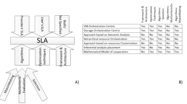
3.1 Taxonomy Tree related to SLA-based Approaches. . . . 61
3.2 a) Taxonomy, b) Approaches used in the analyzed works. 62 4.1 OpenStack Logical Architecture [5]. . . 76
4.2 An example of a basic OpenStack Architecture exploiting self service networking features [5]. . . 79
4.3 Stack4Things core subsystems. . . 82
4.4 Stack4Things FaaS Cloud-side subsystem design. . . 83
4.5 Stack4Things FaaS Edge/Fog-side subsystem design. . . 85
4.6 Architecture of an Arancino.cc system. . . 87
5.1 SHIRS Architecture [6] . . . 96
5.2 Data acquisition and transmission schema [6]. . . 98
5.3 Dashboard for data presentation [6]. . . 100
6.1 Architectural overview of vehicular node and Smart City presented for SCINaS [7]. . . 105
6.2 SCICC experiments results: a) NEDC and SC-NEDC speed comparison; b) Fuel Consumption; c) CO2 emissions. 109 6.3 SCINaS Traffic Light cycles and definition [7]. . . 112
6.4 SCINaS Algorithm’s Flow chart minimizing the city
traver-sal time [7]. . . 113
6.5 SCINaS Algorithm’s fragment minimizing the city
traver-sal time [7]. . . 113
6.6 SCiNaS experiments results: traffic light states. a) NEDC’s
traversal time; b) SCiNaS’s traversal time. . . 115
6.7 SCiNaS experiments results: a) NEDC’s emission of CO2;
b) SCiNaS’s emission of CO2; c) NEDC’s Fuel
Consump-tion; d) SCiNaS’s Fuel Consumption. . . 116
6.8 Average execution times of SCiNaS’s algorithm for each
segments and for each combination of RAM and CPU. . 117
6.9 Execution time Standard Deviation of SCiNaS’s algorithm for each segments and for each combination of RAM and
CPU. . . 117
7.1 The edge-based FaaS system architecture [8]. . . 122
7.2 Stack4Things FaaS Cloud-side subsystem design [8]. . . 123
7.3 Stack4Things FaaS Edge/Fog-side subsystem design [8]. 123
7.4 Overview of a use case when the edge-based FaaS system
can be deployed for enhanced tasks management [8]. . . 125
8.1 Approaches for Cyber-Physical System Functions
Virtual-ization (CPSFV) [9] . . . 129
8.3 Intrusion Surveillance System use case scenario [9]. . . . 136
8.4 Command propagation time with respect to the number of
federated smart environments and IoT nodes involved. . 138
9.1 High Level architecture of the factory FFPS [10]. . . 144
9.2 SB schematics [10]. a) Floor view. b) Whole SB view. . 147
10.1 High Level architecture of the TOO(L)SMART template. 155
10.2 Examples of the map developed through tools available in
List of Tables
2.1 Difference among Fog and Edge Computing Model . . . 28
5.1 Performance metrics comparison [6]. . . 99
6.1 Segment’s parameter passed to SCiNaS in order to
CHAPTER
1
Introduction
C
YBER PHYSICAL SYSTEMS (CPS) are complex, het-erogeneous distributed systems where the cooperation among cyber components (e.g., sensors, actuators, and con-trol centers) and physical processes (e.g., temperature, fire) is deeply intertwined. A CPS is defined as a system where computation, network-ing, and physical processes are integrated to monitor and control physical environments [4]. The adoption of CPSs is due to the advent of theInter-net of Things (IoT). IoT devices are systems with limited computational capabilities that are able to expose their services to the Internet, as long as a TCP/IP stack [11] is available. Sundmaeker et al. [12] state that IoT devices were born in the 1999 in the MIT Auto-ID Lab as technologies including bar codes, smart cards, sensors, voice recognition, and biomet-rics. In 2005 Srivastava [13] identifies the trend pushing technologies in general towards a pervasive dimension, and in particular moving “things” in that direction as well. Sundmaeker again, in [12], deeply analyzes the IoT concepts and perspectives from several points of views, providing an interesting categorization. IoT devices may be equipped with MCU and/or MPU (see4.3) exploiting their facilities to manage the physical devices (sensors: smoke, gas, fire, presence, camera, and so on; actuators: light, valve, traffic lights, motors, and so on) during their life-cycle; at the same time, they may run programs that pre-process the physical signal to produce data useful for several purposes. For example, a single smoke sensor is not enough to identify fire (a cigarette could deceive it). A traditional fire system delivers the signal perceived to a central process-ing system that correlates the signals and decides if it has to activate the alarms, also informing firefighters or surveillance. In this scenario, the need for a unified scheme enabling CPS interactions with IoT devices without resorting to ad-hoc infrastructure, is obvious. Nevertheless, CPSs
are not isles surrounded by “plain” 1 environments, but they are placed side by side with a multitude of other CPS (e.g., Vehicles, Factories, Buildings, Hospital, Street, and more). The pursue to provide a unified solution to manage any kind of CPS is not actually achievable, for several reasons, as detailed in the following.
∙ Administrative constraints: environments belong to several owners, Private or Public, that are free to make choices, in relation to exclu-sive usage and/or sharing of resources, according to various factors: financial, legal, etc.
∙ Technology advancements: CPSs realized in different moments may adopt significantly diverse technologies.
∙ Incompatibility with previously deployed (e.g., possibly legacy) technologies.
As a consequence, research activities were focused on identifying a methodology able to manage such environments (see section2.3), and ac-cording to the literature, the most common solution used is represented by systems able to manage, coordinate, and organize sensors and actuators, host resources and provide support to the development and maintenance of high-level services [14], in a nutshell, a Cloud-like experience. Ear-liest examples of CPS are Smart Buildings (SB), historically defined in
1In this context, when referring to “plain” environments, we are talking about systems that do not leverage IoT device capabilities beyond mere sensing data collection, in summary, that cannot be categorized as Smart environments.
1981 with the term Intelligent Building, coined by the United Technology Building Systems Corporation, then implemented into the City Place Building in Hartford, Connecticut [15]. These “Smart” buildings are mostly customized controlling systems able to provide basic automatic management facilities of the installed devices (e.g., smoke and fire sen-sors, ventilation peripherals, heating systems, etc.). The advent of IoT pushes towards Smart Environments and specifically Smart Buildings. As highlighted in [16], it is hard to construct a unique view of a Smart Building with a commonly accepted definition. In 2009 the European Commission’s Information Society provides a long and complex defini-tion of Smart Building [17] (see section 2.3.1); in summary it may be explained as in the following: a Smart Building is an integrated system based on IoT and Ubiquitous Computing facilities able to take advantage of a range of computational and communications infrastructure and tech-niques. The Smart Building concept is easily adaptable in accordance with several scenarios, modifying system behaviour to achieve a range of results. For example, an SB specialization is related to the industrial context, where the physical processes commonly monitored by an SB (e.g., HVAC, fire, and intrusion control systems) are added to the controls related to the production processes. This way, the system will be able to monitor and quickly react to emergencies coming from the safety systems, but at the same time, it can face production chain issues that are continuously analyzed by the Factory. This is usually indicated as a
Smart Factory [18–20].
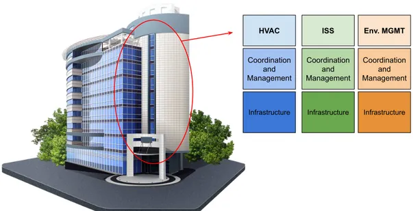
Until now, we have discussed of CPSs involving private environments, but another category of CPSs very relevant and interesting is that of public environments. Streets, public buildings, subways, and so on are commonly considered part of the Smart City [14]. Several entities spent energies in this direction, both at the institutional level (as the EU community) and at the academic and industrial levels as well, with models useful to provide new services, such as: optimizing vehicular traffic flows, enhancing the safety of citizens outdoors, monitoring air pollution levels, enrich public transportation systems, make rescue operations faster and safer, and so on. The CPSs discussed until now are self-consistent; they are able to complete their duties, simply by interacting with IoT devices available within their infrastructure. Furthermore, it is common to find SB composed of several IoT-based systems that are not integrated with others available in the same environment, as shown in figure1.1. These systems can be identified in a wider environment where other CPSs (buildings or in general Smart environments) are available; if they are not physically isolated, it will be possible to interconnect them realizing a new CPS. This way, we obtain a kind of puzzle game composed of several tiles where each one is represented by a Smart Building. As the tiles of a puzzle game, each element has to be interconnected with the other exchanging data, raw or pre-processed, enabling workflows involving the city to support everyday citizens’ lives. With regards to the
HVAC ISS Env. MGMT Coordination and Management Coordination and Management Coordination and Management
Infrastructure Infrastructure Infrastructure
Figure 1.1: An example of coexisting CPSs in a classical Smart Building.
realization of such interconnections, the following question rises: Are the CPSs belonging to the same administrative domain? The answer guides us towards one of the following two solutions:
∙ If the answer is affirmative, we can model our interconnection in a tightly coupled way; adopting the Software-Defined Building approach (see section 2.3.1.1, and chapters 5,8, and 9even if SDB approach is not the main focus).
∙ If negative we are bound to consider a loosely coupled interaction, where not all the capabilities of the systems are shareable, adopting a federated cooperative approach (see section2.2.4)
In the following, we briefly introduce these two approaches.
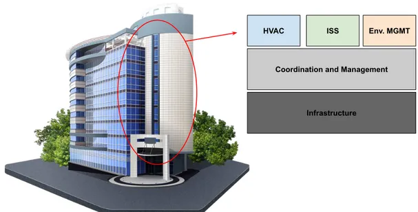
A Software-Defined Building (see figure1.2) can be defined as a build-ing where, in line with the Software-Defined principles, the infrastructure
HVAC ISS Env. MGMT
Coordination and Management
Infrastructure
Figure 1.2: An example of coexisting CPSs in a Software-Defined Building.
and its composing devices are managed in a common way, offering to the upper layer the functionalities to be managed. The upper layer is the management layer, where several facilities are available:
∙ Control and Manage devices of the lower layer,
∙ Orchestrate, aggregate, filter, and preprocess data coming from the infrastructure layer,
∙ Provide facilities, exploitable by applications, where the former expose abstractions of the IoT devices available in the infrastructure layer.
With regards to the federated cooperative approach, we are referring to a complex CPS composed of several smaller CPSs belonging to different administrative domains (such as different private owners, or a mix of
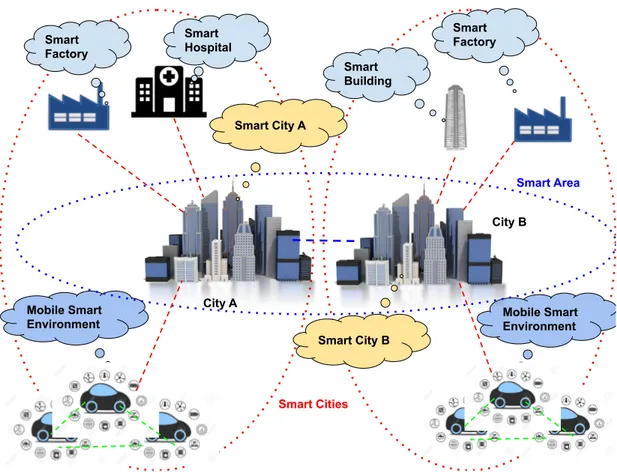
private and public owners). In this scenario, a crucial topic is how the shared CPSs facilities are exploited [9,21]. During the federating process, the domains involved have to sign a sort of agreement that defines the facilities being shared and a typical Service Level Agreement (SLA) used for the cooperation [22–25]. The cooperation system has to avoid SLA’s overwhelming limitations defined and agreed by the involved entities. For this reason, coordination and cooperation patterns for service selection are also evaluated, having a look at the approaches adopted in literature, both in the cases of brokered and decentralized ones (see chapter3). In particular, a complex CPS representing a further step lies in the Smart City research domain. This aggregation of CPSs, as shown in Figure1.3, represents a new dimension for Smart Cities, that is anyway applicable to an even wider range of environments. As an example, it can represent a Smart Metro Area (composed by an aggregation of Smart Cities), or Smart Country, and so on. A federated cooperation among CPSs enables several advantages:
∙ increase the amount and diversity of data available for applications running on CPSs,
∙ enables the sharing of computation resources among CPSs,
∙ creates an infrastructure enabling the exploitation of Cloud, Fog, Edge, Cloud Continuum approaches (see sections2.1.1, 2.1.3,2.1.4,
All the advantages discussed till now about the cooperation among CPSs make the realization of platforms and applications possible, en-abling simplified cross-pollination between service providers, simplifying new developments and reducing the time-to-market for services overall, that translate into advantages for the end user as well. The applications exploitable in a similar scenario are countless. They range from ad-vanced traffic monitoring, management, and driving utilities (see chapter
6, to the realization of enhanced Intrusion Surveillance System based on neighborhood surveillance systems (see chapter8), cooperative emer-gency management that supports rescue activities (such as the firefighters’ activities as described in chapter9).
Another interesting aspect related to CPSs and, in particular, to co-operating ones, is the distribution of computation among the available computing elements. Let us make an analogy among a human and a CPS: we can assume that the eyes and the hands of a CPS are represented by the IoTs, while the body and the brain are equivalent to the Cloud. In this way, the CPS becomes a perfect infrastructure where it is possible to apply the Cloud Continuum2 principles [26]; in particular, we must refer to Fog/Edge and Cloud computing technologies to complete the analogy mentioned above.
Fog and Edge computing [27,28] are paradigms of computing that
2Cloud Continuum represents the paradigms in which the computation is distributed on the whole CPS exploiting Cloud, Fog, and Edge computing facilities (see section2.1.5).
operate near the peripheral of a system. Indeed, they differ for where (on earth) and in which (part of the) system the computation occurs. The latter makes its elaboration into or near the Edge devices (commonly IoTs, but it is exploited also on gateways, or similar). Instead, the former moves the computation to processors connected in the same area network or into the networking gear itself (router, access point, repeater, and so on).
These techniques, supported by new emergent computing paradigms [29] such as Serverless computing (see section2.1.6), enable the CPS to be easily exploited by the applications previously under discussion. In this sense, I have made some preliminary investigations [8] with some prototypes to evaluate some assumptions of how the application of the serverless technique simplifies the setup and the re-configuration of IoT devices through simple function invocations. During my Ph.D. activities, I have organized my main research line to create “a new dimension” for an environment made of cooperating CPSs. This ambitious endeavour took the best part of the time I devoted to research activities during the PhD programme, thus, to better organize my studies, I have structured my research activity as follows:
∙ Literature review.
∙ Hands-on experience about CPSs.
∙ Models and applications for cooperation among CPSs.
∙ Definition of a Template framework to quickly transfer the “smarts” to new environments.
To better describe my research path, in the following each step will be discussed.
In this research trajectory, cooperation schemes and techniques for the selection of resource providers are important issues to be addressed. A literature review to understand the differences among brokered and decentralized Federated Cloud Service Providers is available in [30].
Thanks to the European project BEACON3 [31], experience was matured with typical Cyber-Physical Systems, such as Smart Buildings and Smart Cities.
Another step of my research path has been devoted to face real prob-lems generated in the interaction with a real CPS (small, bigger, or even born by aggregation of other CPSs), taking care of the comput-ing facilities hosted by the CPS itself and other externally available facilities. In chapters 5 and 6, several use cases have been thoroughly analyzed [6], [32], and [7]. The former presents a system to check the level of people occupancy in a room or, more generally, in a closed envi-ronment, exploiting IoT devices for air quality monitoring. The other two works are related to Smart vehicles enhancements, through a constant
3In BEACON the federation techniques for networking resources were implemented to distribute resource computation among Cloud Service providers.
interaction with other CPSs available across the Smart City.
Another relevant aspect studied during my research activities is related to the management of Fog/Edge computing systems that absolve complex tasks by creating pipelines. To explore this specific scenario, I first realized a system able to support the computation distribution upon a cloud-based environment [33]. Then, I used the previous studied “pipeline-based compute distribution techniques” to create workflows running on top of the IoT infrastructure [8]. So, Serverless techniques are applied on a Fog/Edge computing scenario to distribute the application’s workload on the whole CPS and not only on the Cloud.
Finally, I focused my research activities on complex CPSs, by explor-ing applications and systems operatexplor-ing upon multiple CPSs [9] and [10]. This part of the research is related to the use of the Software-Defined Building approach, respectively, in a neighborhood for security purposes and in an industrial district to enhance fire-fighting systems and to sup-port the firemen. I also focused my attention working on projects where the aggregation of multiple CPSs was extremely important [34,35], i.e. the #SmartMe and the TOO(L)SMART projects (see chapter10).
To cover in detail my Ph.D. research activities, the remainder of the thesis is structured as follows. Chapter 2 presents the state of the Art, introducing the technologies, the definitions, and the paradigms useful for my research about cooperative CPSs. Chapter3briefly presents a view of the literature review made on cooperation among Cloud Environment.
Mobile Smart Environment Mobile Smart Environment Smart Factory Smart City A Smart Factory Smart City B City A City B Smart Area Smart Cities Smart Hospital Smart Building
Figure 1.3: An example of a Smart Area.
Chapter 4, introduces the tools and the devices most used during my research. Chapters 5 and 6 describe the applications implemented in the context of a single CPS; then Chapter 7 follows, that presents the investigation on serverless paradigms applied on CPS environments. Chapters 8 and 9 present applications on cooperative CPSs. Finally, Chapter 10describes the template defined for the Smart Cities useful to enable cooperation among CPSs. The last Chapter recaps the work made and outlines some future directions for my research plan going forward.
CHAPTER
2
State of the Art
2.1
Computing Technologies and ParadigmsO
VER the last thirty years the IT world has been sig-nificantly reshaped by the advent of the Internet. The opportunities to easily interconnect systems have pushed forward both the technologies and the techniques available to the system designers and software designers, but at the same time even the problems to be faced have grown with them. This way, new business opportunitiesand new computing paradigms has emerged and has changed the face of telecommunications and business infrastructures and at the same time, it has modified deeply the culture of those peoples who have got in touch with it. In this chapter the most relevant paradigms and techniques are presented.
2.1.1 Cloud Computing
I
N recent years, IT researchers and developers focused their at-tention on developing a new computing paradigm, the so-called Cloud Computing. The technological progress and the IT services evolu-tion allows to offer to the end-user more and more efficient large scale services leading inevitably to an increase in management costs for the providers of such services. For this reason, IT managers has adopted more effective strategies to meet different needs. Indeed, there is a con-tinuously increasing request of QoS (Quality of Service), and the need of lower costs to manage a growing user basin. This is the context where the Cloud Computing is placed.With Cloud Computing, users and companies accede to computing resources, storage and software applications without the need to manage and to maintain the physical resources where them are hosted. These resources, in fact, do not reside locally into a user PC or office cluster anymore, but they are allocated within the cloud, dynamically virtualized
and mapped to physical hosts distributed throughout the network in a totally transparent manner to the end-user. This technology takes the name Cloud to highlight the absence of information about where the services are instantiated.
So, when someone refers to the expression "cloud computing", he is talking about technologies that allows storing and / or processing data, using virtualization technologies to offer hardware or software resources through the network following the user’s demand. The resource are offered in form of services that are modelled typically with a client-server model. These services are accessible to requesting users through interface (e.g., REST API, GUI, and so on) that serves both to provide Access Control facilities to offered services, and also to hide the underlying hardware and software architecture or features used in the execution. In a nutshell, the Cloud Computing paradigm:
1. it provides an abstraction of the hardware and software technologies that the user has requested, guaranteeing a certain level of reliability and system availability, enabling enterprises to concentrate on busi-ness without having the need to assign capital, and human resources, in the purchase and maintenance of hardware and software resources representing the cornerstone of their applications;
2. it provides a reduction of costs to the provider (and thus to the users), because the resource management is carried out in a
dis-tributed manner by algorithms allowing to optimally manage the computational capabilities of the machines, and then to minimize the costs of energy consumption, maintenance and so on;
3. the large companies exploit it in order to create their own private cloud computing system to be used inside company administrative domain. So, it can benefit for all the reasons of reliability, avail-ability, energy saving and maintenance of the above mentioned machines, without facing the risk to fall into the data security and privacy issues.
The virtualization is the key concept on which the cloud computing is based. Virtualization consists in a technology that enables running a virtual instance of a resource (e.g., computer hardware, storage devices, computer networks, etc.) in a layer abstracted from the actual hardware, thus enabling features like compatibility, portability and migration of applications for administrators, and security, reliability and performance to the end user.
Commonly, the resources virtualized are entire systems (called Virtual Machine, VM) that runs on a software “layer”, called Virtual Machine Monitor, VMM (also known as Hypervisor) that separates physical re-sources from the virtual environments that require them. The Hypervisor can be executed on the physical systems exploiting the resources of the hostto produce virtual entities offered to the end-user. Thus, a virtual
machine (VM) can be understood as a logical representation of a physical machine (PM) consisting of hardware and firmware. VMMs assign phys-ical resources dynamphys-ically so that the virtualized environments can use them, and at the same time, they provide other advantages of virtualiza-tion, those are the ability to make backups and status updates, migrations of virtual machines from a host or server to another that, by saving the VM state, will be able to continue its running as if nothing happened.
2.1.1.1 Key Features
I
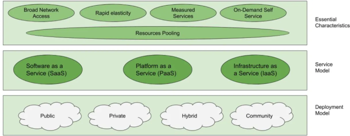
N the 2011th the NIST has released a definition for the cloud computing in the article [36] listing its five essential characteristics that are resumed in the list below:∙ On-demand self-service. The user can request and use autonomously the services offered by the cloud, this means that any human inter-action between the user and service provider is required.
∙ Broad network access. Services have to be available through the Net-work and they have to be accessible through a standard mechanism, thus they can be used on different platforms.
∙ Resource pooling. The provider’s computing resources are pooled to serve multiple consumers using a multi-tenant model. Moreover, the users have no vision of how them resources are allocated, they have
only to concentrate on a logical abstraction of the services without having care of how physical and virtual resources are dynamically allocated by the provider.
∙ Rapid elasticity. In order to allow easy system scalability, the virtual and physical resources MUST be provided as fast and dynamically as possible; this could appear to the users’ eyes as the providers have unlimited resources.
∙ Measured service. The resource usage is measured to apply the fees for the services used. The resources provided by the Cloud have to be adapted to the typology of services acquired.
2.1.1.2 Categories of Cloud Services
C
LOUDcomputing is still one of the major research topics in the IT world and, even if the research has bring it towards several evolution it is still one of the most used and useful computation paradigms. Therefore a standard that represents its architecture doesn’t exist it is possible to classify the main offered services as IaaS, SaaS and PaaS. The Figure2.1shows the general vision of the cloud computing with respect the NIST definitions.
Instead, in Figure 2.2.a are shown how the three service-model are connected as function of the control on the system owned by the
end-Figure 2.1: Cloud Computing Overview: Visual Model of NIST Working Definition of Cloud Computing.
user, in Figure 2.2.b are compared the functionalities are managed by customers or to the providers. At the base of the pyramid there is the IaaS (Infrastructure as a Service). The IaaS is the lowest level of abstraction and it provides to the users a virtual computing infrastructure for the execution of users’ system (e.g., entire platforms or specific application). According to Cloud Computing Rapid Elasticity feature the virtual in-frastructure could dynamically grow or decrease as a function of the actual load and of the requests to be served. Moreover the pay-per-use infrastructure includes all of the hardware needed on the network, for example servers, firewalls, switches with certain characteristics.
On the virtual infrastructure provided, the users will install, configure, manage, and use remotely their frameworks or applications, while the Cloud Provider must ensure the service provided by means the infrastruc-ture configuration, in order to allow its use to the customer. The Cloud
(a)
(b)
Figure 2.2: Cloud Computing service Model Overview: a) Service Model and user control in relation [1]. b) Services managed by the customer and by the provider in the service model [2]
Provider, moreover, had to guarantee the system maintenance and its replacement in case of damage to the machines; the latter is the repre-sentation of the characteristic of the IaaS layer called scalability. This way, computing power and storage resources could be added without
the users’ need to reconfigure everything; so the user could manage its business without the need of estimate the infrastructure costs and jump in the market without the risk of the loss of big capital for the infrastructure that may be unused and thus unnecessary and avoids the user to replace the machines in the future. The second layer of the service model is the PaaS (Platform as a Service), according to this service model the companies offer to the customers hardware and software infrastructures for running their applications without the need to configure them, it is a kind of intermediate service between IaaS and SaaS. A PaaS provider offers to its customers an useful environment for develops, tests and maintains their applications, oblige them only to accept some restrictions on the available tools, APIs and platforms that are balanced by great scalability and lack of the infrastructure management. The higher layer of the cloud stack is the SaaS (Software as a Service). The purpose is to allow remote access, typically via Web, to the services and functions offered by software, the use of which, also in this case, is subjected to the pay-per-use paradigm. The users of this service model, don’t need to install anything or to use particular hardware resources on his local machine, to exploit the most of the SaaS potential.
2.1.2 Cloud and Fog computing in IoT
I
N recent years, big efforts have been put in promoting the Cloud paradigm as a suitable solution for managing IoT environments. Indeed, several methods and techniques have been introduced to deal with the management of a remote and resources’ constrained infrastructure. In this context, issues have been addressed in the literature, such as scalability, device accessibility, and personalization of services. To have an extensive insight into the challenges facing the integration of the Cloud and IoT, readers may refer to [37,38]. In the same perspective, several platforms were introduced to merge IoT deployments within the Cloud management scope [39].Despite the wide range of benefits the Cloud paradigm provides (e.g., in terms of storage and computing resources), novel constraints in terms of Quality of Service (QoS), dictated by current and forthcoming appli-cations, make the Cloud unfit to meet the corresponding requirements.
To work around these intrinsic limitations, the Fog/Edge computing paradigms have been introduced to push resources, such as storage and compute, to the network edge, to be as close as possible to data producers. The fact that Fog computing nodes are bound to be close to data sources is a key enabler of advanced applications [40] that were not feasible when relying only on the faraway Cloud infrastructure.
2.1.3 Fog Computing
C
ISCO made the first introduction of the term Fog Computing in 2012 [27]. The basic idea behind the Fog Computing is to place light-weight facilities (that instead have to be executed inside the Cloud) at the mobile users’ proximity. This way, a preliminary advantage is provided to the system from the characteristics of the connection implemented: with Fog, the connection towards the mobile users is shorter and with less congestion respect the case of the Cloud where the connection path is longer and potentially heavily congested [41]. Other advantages owned by Fog computing, but according to [42], some of the others are:∙ Low latency and real-time interactions,
∙ Save bandwidth,
∙ Support for mobility,
∙ Geographical distribution.
Thanks to the Fog computing model, the data elaboration could be done with a local area network breath, reducing latency into the data and the response delivery; at the same time, it reduces the consumption of bandwidth from the Fog node to Cloud. The Fog model supports, both the mobile than the static devices (even in case of geographically
spread devices), the shifting of the computation in a Fog node near the device position. Into the survey [42], the authors state that most Fog computing architectures are derived by the three-layer structure extending the Cloud computing with the introduction of a Fog layer between Cloud and IoT devices. This way, the Fog server could be a generic virtualized equipment with onboard computing, communication, and storage capabilities to provide services to its users [41].
2.1.4 Edge Computing
E
DGE computing refers to a technology that moves the compu-tation (and the storage in some cases) from a centralized element, such as a cloud computing resource, to the network edge near the data source. This way, not only reduces the latency suffered by the data transmission from the data source to the place in which the decisions are taken, but it increases the data source owner’s privacy avoiding that some data could be delivered in the Cloud maintaining them near the devices. An edge device in this model has the double-role of data pro-ducer and data consumer, so they become not only an appendix of the Cloud but even active elements that could request and offer services to the cloud [43]; this is identifiable with a fine mesh of computational resource abilities [44]. The concept of Edge device has a wide scope that can range from an IoT gateway to a campus network or to an edge compute nodeco-located with a cellular base station; this makes, as highlighted above, the Edge computing as a sort of panacea for the issue related both to network latency and management challenges posed by real-time services. Moreover, Edge computing addresses scalability challenges by exploiting the hierarchical architecture of end-device and computational resources from the Edge compute nodes to the central Cloud compute resources. This way, the system may easily avoid network bottlenecks towards the central compute location scaling with the clients’ number. Often, Edge and Fog computing are confused as it is possible to see in [45]. Still, even if they have the same primary target, the main difference stays in the main focus: the Edge focuses more on IoT peripheral side, while Fog focuses on the infrastructural side [43]. Their differences are shown in Table 2.1, [42], [46].
To complete this overview about Edge Computing a mention is in order for an emerging approach pushed by Telco scientists and by the advent of 5G, which aims to exploit a particular category of edge devices: the highly capable end-devices (e.g., mobile phones and tablets). ETSI promotes this activity,1,which has standardized the Mobile Edge Com-puting (MEC) [47]. The ETSI MEC group Industry Specification Group (ISG) objective is to create an open environment across multi-vendor cloud platforms located at the edge of the Radio Access Network. This will be accessible by application/service providers and third parties
Parameter Fog Computing Edge Computing
Resources Limited More Limited
Proximity to End-Device Near End-Device In the End-Device Focus Infrastructure Level Thing Level Multiple IoT Application Supported Unsupproted Location of data Network edge Devices Edge Devices Table 2.1: Difference among Fog and Edge Computing Model
ing to overcome the challenges related to centralized cloud computing environments, especially in terms of both latency and assurance of higher speeds [48]. The intensive data tasks are pushed towards the edge, locally processing data in proximity to the users, to reach these goals. This way, the mobile network operator can avoid or reduce the traffic bottlenecks in the core and backhaul networks while assisting in the offloading of heavy computational tasks from power-constrained User Equipment (UE) to the edge. The purpose of this initiative is to realize a decentralized cloud architecture that can constitute a technology pillar for the emerging 5G systems, transforming legacy mobile base stations by offering cloud computing abilities and an IT service environment at the edge of the network. Since September 2016, ETSI ISG has dropped the ’Mobile’ out of MEC, renaming it as Multi-access Edge Computing in order to broaden its applicability to heterogeneous networks including WiFi and fixed access technologies [49].
2.1.5 Computing Continuum
T
HE computing technology field after the advent of IoT was per-vaded by a plethora of devices and applications that has to be managed often via the same infrastructure. So Virtualization, Cloud computing and its evolution (Fog and Edge, introduced in the previous sections) are employed to orchestrate the resources involved in homoge-neous way exploiting as much as possible the hierarchical structure that characterizes this computing techniques. We refer to this as Cloud Com-puting Continuum. According to Bittencourt et al. [50], this technology is in literature is analyzed in several works that could be categorized in three main categories:∙ infrastructure,
∙ management,
∙ application.
The management, among the others is most interesting category for our study. Indeed the cooperation among CPSs, even if it is based on federation or not, involves several aspects that are hot topic in literature. Bittencourt [50] identifies a series of works related to the management that are focusing mainly on specific aspects, such as:
∙ serverless computing,
∙ data management and locality.
The first one, resource allocation and optimization, it is a challenging problem became more complex from the new architecture generated by this new computational paradigms. Scheduling problem (NP-Complete) and techniques proposed in literature are sensitive to the application and the infrastructure characteristics [51]. Advent of IoT and Fog comput-ing has introduced a new way allocate the resources, indeed the Fog computing is expecting to fulfill the requirements not managed by the Cloud platforms, but relaying on them to for the others [52,53]. About Serverless computing, we will go deeper in the section2.1.6, we could say that it has modified the traditional cloud-based approach, moving it from the batch-oriented to real-time processing of data. Management of data is an hot topic in literature, anyway only recently the locality of data management has gain relevance being adopted in geo-distributed data centers exploiting Cloud computing continuum (Cloud-Fog-Edge computing) [54–56].
2.1.6 Serverless Techniques
S
ERVERLESS techniques are meant to offer at the end user the chance to run operations without have care of the server (virtu-alized or physically instantiated) where the operation are executed, infew word the reader could consider the serverless paradigm as one of the evolution of the Cloud computing techniques that are focused on the execution of tasks.
2.1.6.1 Serverless vs. Function-as-a-Service (FaaS)
M
OSTinvestigations around this topic, for long have treated these techniques indistinctly as Serverless and Function-as-a-Service, FaaS. This technology is referring to the resources virtualization, introduced by Cloud Computing and its evolution, but according to how virtual-ization activities are managed, we can specifically refer to one or the other. Until 2017, authors confuse these two techniques, referring to them without discriminating whether a full-stack environment, or the execution of a simple function, is required, as in [29], [57], and in a few other works. An interesting definition is provided by Gilkson et al. in [58], where serverless is considered as “a software architecture where an application is decomposed into ’triggers’ (events) and ’actions’ (functions), and there is a platform that provides a seamless hostingand execution environment”, this definition is interesting but it is not useful to distinguish the differences among the two approaches. Several other publications are discussing about the differences existing among the two approaches and even the respective advantages/disadvantages, as in [59], [60], and [61]. In particular, the latter two are respectively
discussing about the serverless approach, and about the trends those are rewarding the FaaS approach. At this point, the researcher has started to identify the difference that characterize these two concepts but any well definition was released.
In the 2018 the Cloud Native Computing Foundation (CNCF) [62] resolve the doubts related to the serverless computing introducing the concept of Backend-as-a-Service (BaaS) in the loop. CNFN defines that Serverless techniques as a technology composed by BaaS and by FaaS, where these two techniques are defined as follow: i) FaaS provides small units of code, representing event-driven computing facilities, where the functions get instantiated and triggered from an external source, typically through commonplace HTTP requests; ii) BaaS, instead, is an approach to handle specific common backend-tasks without any customer’s in-volvement in their management.
2.1.6.2 Fog/Edge computing and Serverless/FaaS
W
ITH the evolution of Cloud solutions, all major Cloud service providers nowadays have a Serverless computing platform in their offer-ing. For instance, Amazon Web Services (AWS) has AWS Lambda2 that makes consumers able to run their code without provisioning the infras-tructure. IBM as well provides a Serverless platform named IBM CloudFunctions3 which is built on top of Apache OpenWhisk [63]. The same for Microsoft Azure and Google that propose Cloud Serverless plans using Azure Functions4 and Google Functions5 respectively thus, their consumers can deploy their functions on the Cloud. With the proliferation of IoT devices, the amount of data generated at the network edge has experiences an immense growth. Examples include sensor data, events generated by IoT devices and gateways, multimedia files such as cameras’ images. To make use of this data and provide new services/applications with added values, the incumbent Cloud players are showing immense interest in the Fog/Edge paradigms and promote the Serverless/FaaS approaches as suited solutions to be adopted at the network edge. In fact, Microsoft has released a Fog/Edge platform for IoT called Microsoft Azure IoT Edge [64] that extends the Cloud Serverless paradigm towards the network edge using the containerization technology. Likewise, Ama-zon and IBM extended their pre-existing proprietary Cloud solutions to the network edge using AWS Greengrass [65] and IBM Watson IoT [66] platforms respectively. AWS Greengrass, for instance, make users able to run AWS Lambda functions on edge devices hence, they can deploy customized applications on the IoT devices.Although opting for Server-less offerings from public Cloud service providers is a widely adopted strategy to deploy applications, one of the biggest issues related to public
3https://cloud.ibm.com/functions/
4https://azure.microsoft.com/en-us/services/functions/ 5https://firebase.google.com/
Cloud Serverless solutions is definitely vendor lock-in. Indeed, Cloud providers can impose their own choices for strongly (user-)restrictive configuration settings, e.g., caps for execution duration of functions, or concurrent executions. Moreover, data privacy, sovereignty and, ul-timately, control, on owned infrastructure as well, are, in this setting, relinquished and cannot be easily reclaimed back by the IoT owner and/or IoT-hosted service user. Such concerns can be addressed and solved if the Serverless paradigm is deployed using a private Cloud environment. It is within this context that our S4T middleware comes in, by providing an open source solution, based on industry-standard protocols and services, that can run on-premises and without relying on third-party datacenters. An administrator can deploy his/her own self-controlled private Cloud and thus, he/she can have total control over the deployment settings and configurations. In the literature, a number of works target the use of the Serverless/FaaS paradigms in IoT deployments, considering the consider-able level of flexibility and efficiency they provide. For instance, authors in [67] proposed a Fog-based Serverless system that supports data-centric IoT services, in particular, they focused their work on a smart parking use case. In the same context, authors in [68] introduced a platform named Kappa that can be used to deploy functions on devices at the network edge.
2.2
Computing Cooperation: Definition & PatternsR
EGARDLESS of the used computing technology involved, the computing technology may refer to one of the following definition of operating context, valid for Cloud as it is valid for its evolutions:∙ Public Cloud: This computing infrastructure is publicly accessible on the Web. Customers pay for the services used, reducing the CapEX assigned normally to the case of "on-premise" services. Examples of these services are Amazon EC2, Azure IoT Edge [64], AWS Greengrass [65], IBM Watson IoT [66], and so on.
∙ Private Cloud: This computing infrastructure, in opposition to the previous, has both suppliers and consumers belonging to the same organization. Even if this approach does not produce a CapEX reduction, the advantages, in terms of reliability availability, and the possibility to use the same infrastructure for multiple projects without having the privacy issues introduced by the Public Cloud, justify the adoption of this kind of infrastructure.
∙ Hybrid Cloud: This infrastructure is a compromise between the previous two: it is publicly accessible even if there are several limitations, and it tries to take advantage of both typologies.The resulting system is more complex of the previous both from the
realization point of view than from the management aspects. For example, a company might decide to use their private infrastructure to store and manage critical data, and instead to exploit the pub-lic cloud services for storing and managing non-critical data and information.
∙ Cloud Federation: This solution is an evolution of the Hybrid one. Here, several providers may be public, private, or hybrid systems accepting to share resources and services with each other. Cloud Federation is what the IT world is heading, but this target opposes various technical and legal nature difficulties.
The rest of this chapter will analyze the pattern available for the designer that wants to realize a system based on cooperative computation.
2.2.1 Peer cooperation
P
EER cooperation pattern is a tightly coupled architecture (see Figure 2.3) in which the Service Providers usually managed with the same technology (e.g.,OpenStack, OpenNebula, and so on), and belonging to the same (or closely coordinated) administrative domain. According to this configuration, each Cloud Manager has the full control over remote resources (e.g., placement control, full monitoring, or VM lifecycle management and migration control). This way, for each Cloud is possible to implement other advanced features as the creation andResources Manager
Resources
Resources Manager
Resources
Cloud Manager Cloud Manager
Network Manager Network Manager
Storage Manager Storage Manager
VM VM
VM VM
S1 S2
Interconnection Network
Figure 2.3: Peer Cooperation Schema
management of a cross-site networks, the cross-site/domain migration of VMs, High-Availability techniques among cloud instances, the creation of virtual storage systems across different Clouds, and so on.
The interaction between entities manager (as example: Cloud Man-ager, Network ManMan-ager, Storage Manager) is usually made through administration level API’s. On top of the CM there could be a SM to simplify service definition, deployment and management.
2.2.2 Hybrid cooperation
H
YBRID cooperation pattern is a more loosely coupled archi-tecture (see Figure2.4) than the peer one. It combines multiple independent Clouds (without have care about if they are Public or Private Clouds) [69] [70] [71].Resources Manager Resources Resources Cloud Manager Network Manager Storage Manager VM VM VM VM S1 S2 Cloud 1 Resources VM S3 Cloud 2 VM User APIs
Figure 2.4: Hybrid Cooperation Schema
This cooperation approach could also be called the cloud bursting model because it combines external resources from remote clouds to extend resources to face the growth of computational/storage needs due to a burst of requests from customers. Due to the different kind of agreement requested by this approach, the management of resources is done through the user’s API; this reduces the action available by the Cloud Manager requesting.
2.2.3 Brokered cooperation
T
HEBrokered cooperation pattern, as it is understandable from its name, is based on a coordinator element called Broker (see Figureindipendent Clouds [72], [73]. The broker can deploy virtual resources in the managed Clouds according to the criteria defined by the user that has requested the resources (e.g., location restrictions, cost restrictions, and so on), and should also provide networking capabilities to enable the interconnection of different resources deployed in geographically dispersed clouds [31]. This cooperation pattern could be realized even with decentralized brokering schemes where several brokering element interacting each other to increase the resilience of the whole system. This way, we assume that, the cloud broker is a multi-cloud Service Manager responsible for managing application and network services across clouds. Similar to the hybrid cloud federation architecture, this architecture is also loosely coupled, since the broker interacts with the different clouds using public cloud interfaces (user level API’s, such as Amazon AWS EC2 API[17] or OCCI[18]) even if these interfaces usually do not allow advanced control over the virtual resources deployed.
2.2.4 Federation
T
HE Cloud Federation represents a specific architecture in which several Clouds cooperates to constitute a single pool of resources that, according to [3], supports three basic features resource migration, redundancy, and combination of complementary resources. This could be achieved both throughout Horizontal (one level of the Cloud stack)Figure 2.5: Brokered Cooperation Schema
and/or Vertical federation (the application stack spans on multiple levels). Anyway, a federation architecture (see Figure 2.6) is another example of loosely coupled cooperation schema combining multiple independent cloud, both Public and Private clouds. This architecture could be consid-ered a hybrid cloud [69], [70], or a specific case of the federation called inter-cloud federation. This is linked to the cloud bursting model, which combines the existing local cloud infrastructure (e.g., a private cloud managed by a CM, such as OpenNebula or OpenStack) with external resources from public clouds (e.g., Amazon EC2, Digital Ocean, etc.), or partner clouds (managed by the same or a different CM). Similarly to the previous, this architecture is loosely coupled, since the local cloud
Figure 2.6: Kurze’s Federation reference architecture [3]
has no advanced control over the virtual resources deployed in external clouds, beyond the basic operations allowed by the federated providers. The interaction between the local Cloud Manager and the various remote clouds could be made via public cloud interfaces (user-level APIâs) and data models (e.g., Amazon AWS EC2 API or OCCI). As in the previous architecture, there could be a Service Manager on top of the Cloud Man-ager. This architecture is the most appropriate to deploy hybrid solutions: support location aware elasticity and build and deploy highly scalable applications distributed over multiple public cloud providers.
2.2.5 Federation Versus Multi-Cloud
N
O universally accepted terminology has been defined to iden-tify a Cloud computing scenario where each Cloud service provider collaborates “horizontally” or “vertically” with other Cloud service providers.However, in our opinion, there are two terms that primarily identify scenarios where multiple Cloud providers interact each other with the aim of improving the service levels provided to users: Cloud Federation and Multi-Cloud. These terms refer to two such scenarios differ both in terms of the interaction between existing Cloud providers and in terms of operating modes .
In a Cloud Federation context, basically a Cloud service provider shares its (currently unused) own resources with other Cloud service providers participating in the same Federation. In this way a Cloud service provider is able to transparently and dynamically enlarge and optimize its own resource capabilities by instantiation of new virtual en-vironments to keep up with incoming user requests. Thus, such a Cloud service provider does not plan to ever deny service or reject requests from their clients, thus keeping a high level of QoS. This interaction is com-pletely transparent to the end-user, comcom-pletely unaware that her Cloud provider is requesting additional resources from other Cloud providers. Moreover the user is not aware whether his service is hosted by his
reference Cloud provider or across multiple federated Cloud providers.
For this reason, we can state that it is reasonable to affirm that the concept of Cloud Federation is Cloud-oriented and not enduser-oriented. In other words, from a Federation perspective, the users of the system are the federated Clouds operating within the Federation and not the end user that asked for service (IaaS, Paas or SaaS).
Cloud Federation is meant to give additional benefits and new business opportunities to Cloud Service Providers. Conversely, the end-user is actually the consumer of any service in a Multi-Cloud scenario. More in detail, we can define a Multi-Cloud as a user-centric solution where a user is aware about the presence of different Clouds, and either the user or another third party is able to make choices about the selection of the Cloud where services or resources will be instantiated. In Petcu et al. [74] a distinction between the concept of Federation and Multi-Cloud is provided.
Generally, there is a Service Provider (a Broker) which is responsi-ble for the provisioning of services for its users. The Service Provider picks out the services from different Cloud Providers taking into con-sideration the users’ requests. In this scenario there is no collaboration or interaction among the Cloud providers engaged by the user. The Broker performs management, negotiation, deployment, monitoring and migration operations only, in order to fulfill the users’ requirements.
2.3
Cyber Physical SystemsC
interaction occurring among “engineered computing and com-Yber-physical systems (CPSs) are systems born from the municating systems” and the physical world. The Berkeley CPS research group provides a complete definition of a CPS:“Cyber-Physical Systems (CPS) are integrations of computation, net-working, and physical processes. Embedded computers and networks monitor and control the physical processes, with feedback loops where physical processes affect computations and vice versa. The economic and societal potential of such systems is vastly greater than what has been realized, and major investments are being made worldwide to develop the technology. The technology builds on the older (but still very young) discipline of embedded systems, computers and software embedded in devices whose principle mission is not computation, such as cars, toys, medical devices, and scientific instruments. CPS integrates the dynamics of the physical processes with those of the software and networking, pro-viding abstractions and modeling, design, and analysis techniques for the integrated whole.” [4].
As it is possible to see from the taxonomy shown by figure2.7, The diffusion of IoT devices has involved all the everyday life environments, making these scenarios fertile ground for the establishment of Cyber Physical Systems where application aiming to exploit CPS’ facilities can
easily run producing value for their users. The studies on CPSs began a
Figure 2.7: Cyber Physical System taxonomy [4]
long time ago, and to this day, this continuously evolving concept has not been fully explored, and it continues to be a current issue. The interest in CPS starts in 2004 when the European Union (EU) began the ARTEMIS6
project, which was interested in the structural challenges pursued by the European industries [75]. Analogously, the National Science Foundation (NSF) since 2006 has founded a research project titled “Science of Inte-gration for CPSs”. Several research entities and Universities, to mentions some “UC Berkeley,” and “General Motors Research and Development Center” have joined in this project [76,77] Researchers have focused their studies on CPS, starting from the theoretical foundations, design and implementation, real-world applications, and education. Next, the researches spread out to energy management, network security, data transmission and management, model-based design, control technique, system resource allocation, and applications.
A complete overview of CPSs is provided by Wan et al. in 2011; in their review [78], they analyze the research made in the several fields such as Energy Management, Network Security, Data Transmission and Management, Model-based Design, Control Technique, System Resource Allocation, Applications. Nowadays, several challenges are opened and under analysis, even if uncountable researches were done in this field. Among others, Smart-Cities and more in general “Smart” Environments are the most common scenarios in relation to CPSs. Anyway, we cannot forget, among open challenges, unmanned vehicles, real-time systems, and similar research topics, connected to CPSs, that are central in people’s lives.
2.3.1 Smart Building
T
HE history of Smart Buildings began in 1981, with the term In-telligent Building coined by United Technology Building Systems Corporation, then implemented into the City Place Building in Hartford, Connecticut [15]. The first examples of Smart Buildings are sort of controlling systems able to manage in an automatic way the building devices (e.g., smoke and fire sensor, ventilation peripheral, heating sys-tems, etc.). More or less around the early 1990s with the first examples of communication protocols enabling the Smart Building’s autonomous control systems: BACnet and LonWorks, that respectively through direct connection with a set of certified devices or the mediation of Neuron chip can interconnect the devices to the controller to manage the former. In particular,in [79] is presented a comparison of those two systems. The advent of the IoT devices pushes towards Smart Environments and specif-ically Smart Buildings. As highlighted in [16], it is hard to construct a unique view of Smart Building with a definition commonly accepted. Anyway, citing the European Commission’s Information Society is possi-ble to define a Smart Building as a “building empowered by ICT in the context of the merging Ubiquitous Computing and the Internet of Things: the generalisation in instrumenting buildings with sensors, actuators, micro-chips, micro- and nano-embedded systems will allow to collect, filter and produce more and more information locally, to be furthercon-solidated and managed globally according to business functions and service” [17]. Trying to simplify the previously definition is possible to say that a Smart Building is an integrated system based on IoT and Ubiquitous Computing facilities able to take advantage of a range of computational and communications infrastructure and techniques.
From the literature we have identified several approaches used to study the Smart Buildings: in [80] the authors analyze a set projects concerning Smart Home projects concerning three main topics: Comfort, Health-care, and Security; in [81] the authors examine two kinds of works from the point of view of efficient energy consumption: Intelligent Building and Small Residential Buildings.
2.3.1.1 Software-Defined Buildings
The vast majority of the papers discussed in the literature present ap-proaches that are tightly coupled to the building structure and didn’t take into account the advantages provided by a Software-Defined approach. The research group of Berkeley [82] made some steps in this direction, In particular they define their approach as follow: “develop software-defined buildings, to shatter existing stovepipe architectures, dramatically re-duce the effort to add new functions and applications without “forklift upgrades,” and expand communications and control capabilities beyond a single stand-alone building to enable groups of buildings to behave cooperatively and in cooperation with the energy grid”; one of the most
exciting works related to Berkeley’s research in Software-Defined Build-ing are related to definition of a BuildBuild-ing OperatBuild-ing System as shown in [83], [84] and [85]. As stated above, the main enabling technology behind a smart building are those related to IoT.
CHAPTER
3
Literature analysis: Study on Cloud
cooperation approaches and on
services/providers selection techniques.
T
HE best way to identify the right approach to enable CPSs to cooperate among them is understand from literature how the same issues are managed in adjacent contexts, such as Cloud Service Provider (CSP) selection. Indeed, thechallenges of building a cooperation-based computing environment are easily compared with those related to the construction of a cooperation-based cloud environment; so my first step is to analyze the literature about this topic. The IT sector’s academics are continuously looking for new solutions, technologies, and protocols to construct a valid computing cooperative system composed of computing environments, essentially Clouds, belonging to different owners.
The first part of my literature analysis concerns the publications pro-duced by the European Union (EU) projects and other published works about Federation or Multi-Cloud topics. The key concepts identified from the preliminary analysis of EU projects are used during the literature review made in the second step. This way, a classification of the papers reviewed used in the selection process is provided.
3.1
EU Projects OverviewI
N the following, a systematic overview of the most relevant EU project is provided. In the end, a summary of the lesson learned and of the concepts adaptable to CPS environments will be provided. Moreover, the knowledge acquired by this analysis is used to filter the remaining literature review, shown in section3.2.Barri-ersis funded by the European Commission in the Seventh Framework Programme (FP7/2006-2013). The project began in November 2007, and it was concluded in January 2011 [86].
The project aims to extend, integrate, and combine the following technologies: Virtualization, GRID computing, and Business Service Management. This project’s results generated much interest in high-performance scientific computing because it enhanced the job scheduling (typical in grid-computing) with the capabilities related to the virtual computing resources. In a few words, RESERVOIR made “virtualization-aware” the grid computing. The goals of the project RESERVOIR are mainly two: infrastructure and VM placement. Infrastructure was de-signed to enable the dynamic relocation of a VM in any grid node without having care of location, network configuration, and administrative do-mains. This project uses federation concepts to define where a VM has to be placed according to the best mapping criteria.
StratusLab [87] is funded by the European Commission in the Sev-enth Framework Programme (FP7/2006-2013). The project began in June 2010, and it was a 24-months project. StratusLab is meant to provide mechanisms to efficiently exploit computing resources for the system administrators and resource providers. It follows a Hybrid architecture model to leverage the external resources to the requesting entities.
BonFIRE [88] is funded by the European Commission in the Sev-enth Framework Programme (FP7/2006-2013); it ran from June 2010 to
![Figure 2.2: Cloud Computing service Model Overview: a) Service Model and user control in relation [ 1 ]](https://thumb-eu.123doks.com/thumbv2/123dokorg/4577227.38555/36.892.139.747.153.789/figure-cloud-computing-service-overview-service-control-relation.webp)
![Figure 2.6: Kurze’s Federation reference architecture [ 3 ]](https://thumb-eu.123doks.com/thumbv2/123dokorg/4577227.38555/55.892.311.613.167.548/figure-kurze-s-federation-reference-architecture.webp)
![Figure 2.7: Cyber Physical System taxonomy [ 4 ]](https://thumb-eu.123doks.com/thumbv2/123dokorg/4577227.38555/59.892.155.779.215.839/figure-cyber-physical-system-taxonomy.webp)
![Figure 4.1: OpenStack Logical Architecture [ 5 ].](https://thumb-eu.123doks.com/thumbv2/123dokorg/4577227.38555/90.892.125.753.765.1059/figure-openstack-logical-architecture.webp)
![Figure 4.2: An example of a basic OpenStack Architecture exploiting self service networking features [ 5 ].](https://thumb-eu.123doks.com/thumbv2/123dokorg/4577227.38555/93.892.158.757.209.669/figure-example-openstack-architecture-exploiting-service-networking-features.webp)
