Università Politecnica delle Marche
Scuola di Dottorato di Ricerca in Scienze dell’Ingegneria Curriculum in Ingegneria Industriale - Meccanica
---
Study and Development of a Novel
Radio Frequency Electromedical Device
for the Treatment of Peri-Implantitis:
Experimental Performance Analysis,
Modelling of the Electromagnetic
Interaction with Tissues
and In Vitro and In Vivo Evaluation
Ph.D. Dissertation of:
Gloria Cosoli
Advisor:
Prof. Enrico Primo Tomasini
Università Politecnica delle Marche
Scuola di Dottorato di Ricerca in Scienze dell’Ingegneria Curriculum in Ingegneria Industriale - Meccanica
---
Study and Development of a Novel
Radio Frequency Electromedical Device
for the Treatment of Peri-Implantitis:
Experimental Performance Analysis,
Modelling of the Electromagnetic
Interaction with Tissues
and In Vitro and In Vivo Evaluation
Ph.D. Dissertation of:
Gloria Cosoli
Advisor:
Università Politecnica delle Marche
Ringraziamenti
Alla fine di questa tesi, che posso considerare il mattoncino conclusivo del mio percorso di dottorato, posso senza dubbio affermare che nella vita nessun traguardo si raggiunge da soli, perché ci sarà sempre qualcuno che, in un modo o nell’altro, ci darà una mano, un consiglio o semplicemente ci dirà le parole giuste, quando da soli ci sentivamo persi. La prima persona che voglio ringraziare per esserci sempre è Simone, da qualche mese mio marito… fa ancora strano chiamarti così! Credo non ci sia cosa più bella nella vita che avere qualcuno al proprio fianco ogni giorno, con cui condividere tutto e con cui costruire un passo dopo l’altro la propria famiglia. A te va un grazie enorme, perché non mi hai lasciato sola neppure un giorno... spero tanto di riuscire a ricambiare quello che fai per me! Per seconda voglio ringraziare Mery, l’amica di una vita, la mia piccola grande donna! Negli ultimi mesi la nostra amicizia è diventata ancora più forte e non smetterò mai di dirti quanto sono orgogliosa di te e che per te ci sarò sempre e per qualsiasi cosa, anche quando non dovessimo essere vicine. Sei come una sorella per me e sì, per te sarei disposta a fare quello che non farei neanche per me!
Un grazie va anche ai miei altri amici... a quelli che mi conoscono da quando ero solo una bambina, a quelli conosciuti nei periodi del liceo e dell’università, alle persone incontrate per caso che hanno subito conquistato un posto nel mio cuore! Voglio ringraziare in particolare Alessia e Lucia, che negli ultimi anni sono ormai diventate una parte fondamentale della mia vita. Grazie perché ci siete sempre e siete davvero delle persone speciali, che io ho la fortuna di avere come amiche. Con le vostre parole sapete sempre come prendermi e incoraggiarmi anche nei momenti più difficili… vi voglio tanto bene! A seguire (ma non per importanza!) voglio ringraziare la mia famiglia e i miei nonni. Mi avete visto crescere e so che per voi sono sempre stata motivo di orgoglio, me l’avete sempre ripetuto (a volte facendomi anche sentire in imbarazzo!) e avete sempre creduto in me. Grazie perché mi avete supportata e mi avete fatto crescere e diventare la donna che sono oggi.
Un grazie va quindi ai miei colleghi, in particolare Sara, Luigi, Filippo e Rachele: volenti o nolenti, siete dovuti stare al mio fianco ogni giorno di questi 3 anni! Ma non siete semplici colleghi, per me siete diventati dei veri amici! E lo stesso vale per gli ex-colleghi, che vedo ormai poco ma che hanno un posticino nel mio cuore… tra di loro un grazie particolare va ad Ilaria ed Annalisa, che mi piacerebbe avere ogni giorno al mio fianco!
Grazie a Lorenzo Scalise (non ti chiamo Prof perché sennò ti arrabbi!), perché è riuscito ad ascoltare ogni giorno le mie preoccupazioni e mi ha aiutato a chiarire i miei dubbi. Grazie perché hai creduto in me e hai dimostrato di fidarti delle mie capacità (più di quanto io stessa mi fidi!).
Grazie anche a Gerardo Tricarico, che ha avuto l’idea iniziale ed ha contribuito alla realizzazione di questo progetto di ricerca.
Per ultimo, non per importanza, un sentito ed enorme grazie va al Professor Enrico Primo Tomasini, mio tutor in questo Dottorato, che mi ha accolta nel suo gruppo di ricerca come quasi fossi una figlia. Grazie Prof perché crede in me e si fida delle cose che faccio. Sono felice che continueremo a lavorare insieme nei prossimi mesi e spero che sarò ancora motivo di orgoglio per lei.
Gloria
Acknowledgements
At the end of this PhD thesis, which I can consider as the last brick of my doctoral project, I can state without any doubt that in life you never reach a goal on your own. In fact, there will be always someone who gives some help, some advice or simply finds the right words, when we all alone get lost.
The first I wish to thank for being always present is Simone, who is my husband since some months… still feels weird to call you that! I think there is nothing more beautiful in life than having someone beside you, with whom sharing everything and building together your family, step by step. I would like to thank you immensely because you’ve never let me alone, not even a single day… I really hope that somehow I am able to pay back everything you do for me!
Then, I would like to thank Mery, my lifelong friend, my little big woman! In latest months our friendship has become stronger and stronger. I will never stop to tell you how much I’m proud of you! I’ll always be there for you, for anything, also when we are not close to each other. You are like a sister to me and yes, for you I would be willing to do what I wouldn’t do even for me!
I would like to thank also all my other friends… those who know me since I was only a child, those met during high school and university, those met by chance who have immediately conquered a room in my heart! I wish to thank particularly Alessia and Lucia, who in recent years have become fundamental in my life. Thank you because you are always present. You are very special people and I am so lucky to have you in my life. You always know how to handle me and to support me even in the most difficult situations… I love you so much!
To follow, I would like to thank my family and my grandparents. You have seen me grow up and I know you have always been proud of me. You have always told it to me (sometimes making me feel embarassed!) and you have always believed in me. Thank you because you have supported me and made me grow and become who I am today.
Thank you to my colleagues, in particular to Sara, Luigi, Filippo and Rachele: willing or not, you had to be at my side everyday in last 3 years! But you are not simple colleagues, you have become real friends for me! And this is true also for my ex-colleagues, who I rarely meet but I have a room in my heart for you. I would like to especially thank Ilaria and Annalisa, whom I wish to have by my side everyday!
I would like to thank Lorenzo Scalise (I don’t call you Prof or you get angry!), because he has been able to listen to my worries everyday and has satisfied my doubts. Thanks because you have believed in me and you have proved to be confident in my capabilities (more than I myself am confident in them!).
I would like to thank also Gerardo Tricarico, who has got the original idea and contributed to the realization of this research project.
Last but not least, I wish to immensely thank Professor Enrico Primo Tomasini, who is my tutor in this research project. You have greeted me in your research group almost as a daughter. Thank you Prof because you are confident in what I do. I am happy I will continue working with you over the next months and I hope you will be proud of me again.
Gloria
Motivations and aims of the work
Peri-implantitis is a serious disease and, to this day, it represents the main cause of implant failure. It affects soft and hard tissues surrounding a dental implant; more precisely, it is characterized by inflammation, bacterial growth and bone level reduction. It can be caused by different factors, like poor oral hygiene and periodontitis. The prevalence is estimated at 9.6% of annually placed dental implants (over a million only in Italy).
Huge amounts of money (some billion dollars) are at stake, so there is a great interest in finding new therapies for such pathology. In fact, different therapies exist (e.g. non-surgical treatments, antibiotics, antiseptics and laser therapy), but none has proved to be satisfactorily effective (the state of the art is reported in Chapter 1). So, at present, prevention is the only way to contrast peri-implantitis.
But in recent years an electric therapy based on the application of a radio frequency alternating electric current was administered by Dr. Tricarico in his dental laboratory (the detailed description of this therapy is in Chapter 2). Such a treatment was first employed in 2002, when the positive effects on peri-implantitis characteristics were observed by chance during endodontic root canal treatment. However, the underlying mechanisms were not known, even if the outcomes were very interesting. Follow-up data concerning the treated patients are available up to 2015; they represent the clinical evidence of the effectiveness of such an innovative electric therapy.
This PhD study aims to investigate the working principle of the aforementioned treatment, in order to better understand the underlying mechanisms and to connect them with the therapeutic benefits (e.g. Which physical factor causes inflammation reduction? Which one promotes the bone healing?).
So, starting from the clinical evidence provided by the above cited clinical trial (Paragraph 2.1), the author wants to characterize the therapeutic device in terms of equivalent model and electrical parameters (e.g. power delivered during a therapeutic session) (Paragraph 2.2). Then, the model will be used in numerical simulations made on a 3D geometry (Paragraph 2.3), in order to observe what happens during the therapy delivering. In this way, it will be possible to try to understand the causes of the observed positive effects on the pathology symptoms.
Moreover, it is desirable to improve the therapy, for example by localizing the inflamed portion of the tissue, so limiting the involvement of the surrounding healthy area. The therapy could also be personalized according to the severity of the pathology. This information could be gathered by means of bioimpedance measurements, since the physio-pathological condition of a biological tissue determines its electrical properties (in particular, electrical conductivity and relative permittivity). Also in this part of the study, numerical simulations were run in order to investigate the feasibility of such an approach (Paragraph 3.1). Then, experimental measurements were made on three patients with dental implants (healthy, inflamed and peri-implantitis cases); in addition, bioimpedance measurements were performed on natural tooth roots of healthy subjects, in order to evaluate the repeatability of such measures (Paragraph 3.2).
As the concluding part of the project, a prototype of a specific device dedicated to peri-implantitis therapy is being developed (Appendix). The certification process is still underway and the relative documentation is being drawn up.
Abstract
Peri-implantitis is a severe disease affecting both the hard and the soft tissues around a dental implant. This pathology presents three main characteristics: soft tissues inflammation, bacterial growth at the implant-tissue interface and bone loss around the implant itself. There is a great interest on peri-implant disease, since its prevalence is estimated at 9.6% of the annually placed dental implants (i.e. millions of implants), for a global market of some billion dollars.
Nowadays, there are different therapies, such as mechanical treatment, antibiotics, antiseptics and also laser therapy. However, none of these are satisfactorily efficient, so that at present prevention is the only means to contrast peri-implantitis.
In recent years, an innovative therapy based on the administration of radio frequency electric current has been experimented in a clinical trial, reporting a success rate equal to 81% of the treated implants. These outcomes were significant, so that the used device (originally designed for endodontic treatment) has been electrically characterized, also providing an equivalent circuit.
In order to better understand the underlying mechanisms of the therapy, the treatment has been numerically simulated in COMSOL Multiphysics® environment. In particular, the therapeutic device has been modelled by means of its equivalent circuit and a simplified geometry of the implant screwed in the jawbone and the surrounding tissues has been realized. In this way, it has been possible to analyse the electric current and field distributions in peri-implant tissues when the therapeutic signal is applied. From the results, it is possible to infer that the anti-inflammatory effect is probably associated to the electric current, which is focused on soft tissues and particularly on their inflamed portion (because of the higher electrical conductivity with respect to the surrounding tissues), while perhaps the bone regeneration effect is linked to the electric field, whose lines cross both hard and soft tissues surrounding the implant.
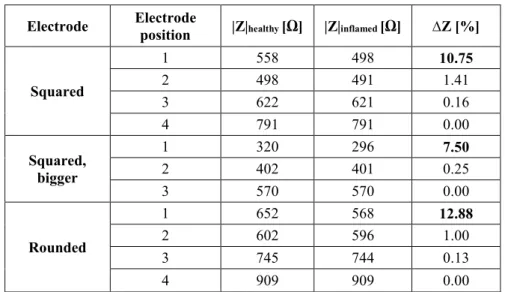
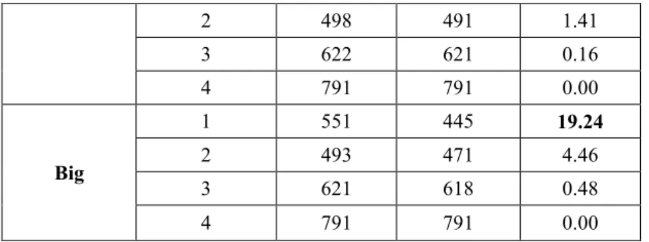
Since healthy and inflamed tissues have different electrical properties, the authors have investigated the use of bioimpedance measurements to localize and quantify inflammations. The feasibility of this approach has been studied by means of numerical simulations of the measure. From the numerical results, it is possible to observe changes in the measured impedance modulus equal to 4-20%, depending on different parameters (e.g. electrodes size and shape or inflammation severity and dimension). In experimental measurements, the observed variations are also more evident: 35% in case of mere inflammation and 56% in case of peri-implantitis (which includes also bone loss, causing a further impedance decrease). This is partly due to the fact that in reality the inflamed tissue is swollen and so the impedance is lower, but, for the sake of simplicity, in the realized model geometry this has not been represented. Anyway, bioimpedance measurements seem to be suitable to discriminate between healthy and inflamed tissues, even if it is necessary to carry out a measurement campaign including a wider population, in order to build a database allowing the classification of individual measurements (in fact, at present only comparison between healthy and impaired tissues is possible). The inclusion of bioimpedance measurement in the proposed treatment would make possible to personalize the therapy according to the severity of the disease and to focus the therapeutic current on the impaired area.
In order to study the repeatability of bioimpedance method in oral environment, experimental measures have been made on natural tooth roots; the results have been compared to the numerical ones obtained from the simulation of bioimpedance measurements on different teeth (i.e. incisor, canine and premolar). The order of magnitude is the same (i.e. some kΩ), even if there are differences probably attributable to a different electrodes positioning and to the actual contact surface between electrodes and gingiva. With regard to the repeatability, an intra-subject variability equal to 10% has been reported in the same day, but the value goes up to 26% in different days. Inter-subject variability has been assessed at higher values (e.g. ≈ 20% for the premolar tooth root).
Furthermore, the electrical safety of the device has been accurately taken into account, also towards the certification process. First of all, the applicable directives have been individuated: IEC 60601-1 (dealing with the safety of medical electrical systems and the necessary requirements to protect the patient, the operator and the surroundings), the collateral standard IEC 60601-1-2 (defining the tests to assess the performance of a medical electrical device in presence of electromagnetic disturbances/emissions) and the particular standard IEC 60601-2-2 (providing requirements for basic safety and essential performance of high frequency surgical equipment, such as surgical knife, which is similar to the considered therapeutic device in terms of working frequency and signal amplitude). Preliminar in vitro tests have been carried out in order to evaluate the effect of the therapy on cell vitality. The setup configuration has been chosen according to the results of numerical simulations, to avoid interferences between different cell cultures and to define the optimal test arrangement. The results show the electric current and field distributions and also confirm that the chosen plastic container for the cell cultures (i.e. Petri dishes) are suitable, since no interferences between adjacent dishes have been observed. The experimental results have shown that the therapy does not cause a significant increase in necrosis (the assessed vitality was of ≈ 85% for the tests versus 94% of the controls); the main negative effect is apoptosis, which is a kind of programmed cell death, granting advantages during the life cycle of an organism.
One last point concerning the safety of the device has been the numerical simulation of possible thermal effects produced by the therapy, potentially caused by the Joule effect. The results have shown that the temperature distribution is not significantly influenced by the treatment (the global temperature increase in the implant surroundings is < 1°C, except for those elements close to sharp edges, which cannot be considered reliable because of numerical errors due to field singularities). This let us state that the proposed therapy for peri-implantitis does not produce dangerous heating effects on the surrounding tissues. Finally, a new device, named PeriCare®, has been designed specifically for the treatment of peri-implantitis disease. It includes both a diagnostic part and a therapeutic one, aimed at bioimpedance measurement and therapeutic signal administration, respectively. Proper electrodes are being designed for such purposes and the prototype is being realized. A sort of block diagram has been drawn and the device instruction manual is available. The technical file is being compiled and the conformity verification tests are being planned in order to start the certification process to obtain the CE marking. Hopefully, the medical device will be placed into the market during this year.
Contents
Introduction ... 1
1.1. Dentistry and oral pathologies: dental implants and peri-implant diseases ... 1
1.2. Current peri-implantitis treatments ... 5
1.3. New perspectives in electrotherapy and electromagnetic stimulation ... 6
Radio Frequency Alternating Current (RFAC) therapy ... 9
2.1. Clinical trial ... 10
2.1.1. Materials and methods ... 10
2.1.2. Results ... 12
2.1.3. Discussion and conclusions ... 13
2.2. Electrical characterization of the therapeutic device ... 15
2.2.1. Materials and methods ... 16
2.2.2. Results ... 18
2.2.3. Discussion and conclusions ... 23
2.3. Numerical simulation of the therapy ... 25
2.3.1 Materials and methods ... 26
2.3.1.1. COMSOL Multiphysics® ... 26
2.3.1.2. Tooth geometry ... 27
2.3.1.3. Tissues electrical properties ... 29
2.3.1.4. Therapeutic device model... 30
2.3.1.5. Simulation parameters ... 31
2.3.2. Results ... 32
2.3.2.1. Results – dental implant (peri-implantitis) ... 32
2.3.2.2. Results – natural tooth root (periodontitis) ... 34
2.3.3. Discussion and conclusions ... 35
Bioimpedance measurements: inflammation detection ... 38
3.1. Numerical simulation of bioimpedance measurements ... 41
3.1.1. Dental implant model: bioimpedance measurements simulation ... 41
3.1.1.2. Results ... 44
3.1.1.3. Discussion and conclusions ... 46
3.1.2. Natural tooth root model: bioimpedance measurements simulation ... 47
3.1.2.1 Materials and methods ... 47
3.1.2.2. Results ... 48
3.1.2.3. Discussion and conclusions ... 50
3.1.3. Experimental validation and self-consistency of the model ... 50
3.2. Experimental measurements on patients ... 53
3.2.1. Measurements on patients ... 53
3.2.1.1 Materials and methods ... 53
3.2.1.2. Results ... 55
3.2.1.3. Discussion and conclusions ... 56
3.2.2 Measurements on healthy subjects ... 57
3.2.2.1 Materials and methods ... 57
3.2.2.2. Results ... 58
3.2.2.3. Discussion and conclusions ... 62
Electrical safety of the therapy ... 65
4.1. Regulations and standards for electromedical devices: IEC 60601-1 ... 68
4.1.1. IEC 60601-1-2 ... 72
4.1.2 IEC 60601-2-2 ... 73
4.2. Evaluation of cell vitality ... 75
4.2.1. Numerical simulation of in vitro tests ... 75
4.2.1.1. Materials and methods ... 75
4.2.1.2. Results ... 77
4.2.1.3. Discussion and conclusions ... 81
4.2.2. In vitro tests ... 81
4.2.2.1. Materials and methods ... 81
4.2.2.2. Results ... 82
4.2.2.3. Discussion and conclusions ... 84
4.3.2. Results ... 87 4.3.3. Discussion and conclusions ... 89
Discussion and conclusions ... 91 Appendix: PeriCare® prototype ... 95
User instruction manual ... 97 Instruction for use ... 97 General information ... 104 List of tests for CE marking ... 106 Electromagnetic Compatibility tests ... 106 Quality manual ... 108 Technical file ... 109 Certification process ... 110
List of Figures
Figure 1. Dental implant components: implant, abutment and crown ... 1 Figure 2. Peri-implant mucositis (left) and peri-implantitis (right) ... 3 Figure 3. Probing of the implant: bleeding (left) and suppuration (right)... 4 Figure 4. Radiographic image of a peri-implantitis case ... 4 Figure 5. Electrodes positioning: after having removed the crown and the abutment (B), the active electrode is screwed into the fixture, while the neutral one is put in contact with gingiva (C) ... 11 Figure 6. Distribution of the positions of the treated implants ... 11 Figure 7. Number of implants treated per year ... 11 Figure 8. Example of gingiva conditions before the therapy: A) with suppuration, B) with deep gingival pockets and C) with bleeding on probing; and after the therapy: D) healthy gingiva (no inflammation) ... 12 Figure 9: Example of x-ray image of an implant in three different moments: A) before the therapy, B) 1 month after the treatment and C) 8 months after the treatment... 13 Figure 10. Endox® Endodontic System ... 15 Figure 11. Endox® scheme: black box with two different functions, that is the measurement of root canal length (i.e. apex locator) and treatment (i.e. Radio Frequency - RF - power generator) ... 16 Figure 12. Thevenin's theorem principle scheme: any black box containing current/voltage sources and resistors can be replaced by a series connection between an equivalent voltage source (Vth) and an equivalent resistance (Rth) ... 17
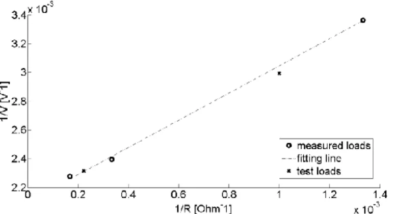
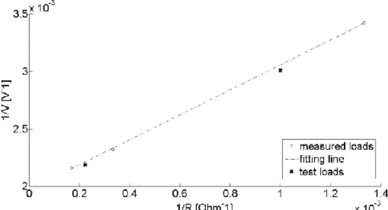
Figure 13. Thevenin electrical circuit and measurement resistor (R) ... 17 Figure 14. Fitting line between 1/V and 1/R obtained on three measured loads and verified on two test loads - incisor power level ... 19 Figure 15. Fitting line between 1/V and 1/R obtained on three measured loads and verified on two test loads - canine power level ... 19 Figure 16. Fitting line between 1/V and 1/R obtained on three measured loads and verified on two test loads - premolar power level ... 20 Figure 17. Fitting line between 1/V and 1/R obtained on three measured loads and verified on two test loads - molar power level ... 20 Figure 18. Fitting line between 1/V and 1/R obtained on three measured loads and verified on two test loads - molar power level plus boost ... 20 Figure 19. Power curve shape (solid line) with measured power values (circles) - incisor power level ... 21 Figure 20. Power curve shape (solid line) with measured power values (circles) - canine power level ... 21 Figure 21. Power curve shape (solid line) with measured power values (circles) - premolar power level ... 22 Figure 22. Power curve shape (solid line) with measured power values (circles) - molar power level ... 22 Figure 23. Power curve shape (solid line) with measured power values (circles) - molar plus boost power level ... 22
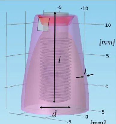
Figure 25. Teeth anatomy chart, with maxillary and mandibular arches ... 28 Figure 26. Natural tooth and dental implant comparison: they are similar in shape and dimensions, in order to allow a proper behaviour of the prosthesis... 28 Figure 27. Model geometry of the dental implant screwed in the jawbone: d is the implant diameter (4 mm), l its length (14 mm) and t the gingiva thickness (1 mm) ... 29 Figure 28. Geometry of a natural premolar tooth root - frontal section ... 29 Figure 29. Electrodes positioning in case of natural tooth root treatment (periodontitis) .... 31 Figure 30. Meshed geometry (tetrahedral mesh) – dental implant model ... 31 Figure 31. Meshed geometry (tetrahedral mesh) – natural tooth root model ... 32 Figure 32. Electric current density distribution (peri-implantitis) - frontal section ... 33 Figure 33. Electric field distribution (peri-implantitis) - frontal section... 33 Figure 34. Distribution of electric current lines with different neutral electrode positioning: upper (top) and lower (bottom) positioning allows to drive the electric current lines in different tissue portions ... 34 Figure 35. Electric current density distribution (periodontitis) - frontal section ... 34 Figure 36. Electric field distribution (periodontitis) - frontal section ... 35 Figure 37. 3D model geometry of the dental implant screwed in the jawbone, with a portion of inflamed gingiva; d is the diameter of the fixture, l its length and t the gingiva thickness along the bone curvature ... 42
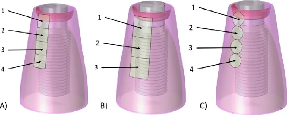
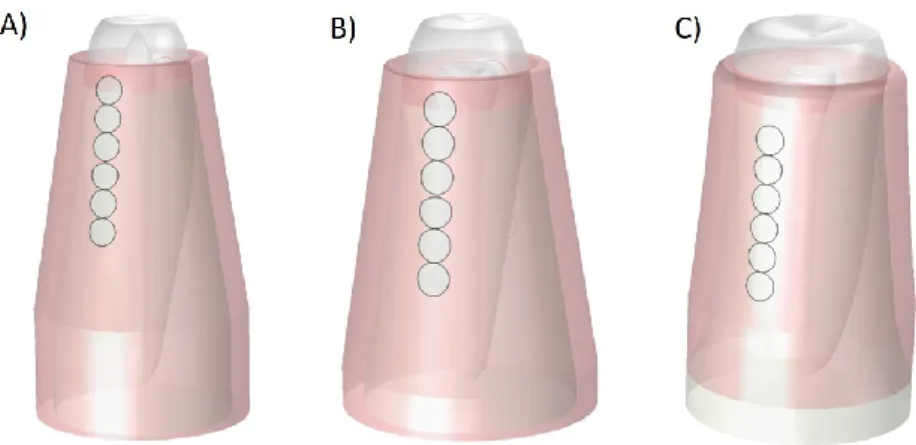
Figure 38. Neutral electrode sequential positioning to locate the inflamed region: A) square electrode (4 mm2), B) bigger square electrode (9 mm2) and C) rounded electrode
... 43 Figure 39. AC sinusoidal generator connected between active and passive electrodes ... 44
Figure 40. Natural tooth roots models with inflammations concerning incisor (A), canine (B) and premolar (C) teeth – square electrodes... 48
Figure 41. Natural healthy tooth roots models concerning incisor (A), canine (B) and premolar (C) teeth – rounded electrodes ... 48
Figure 42. Geometry used for the validation of numerical models - A) simulated and B) experimental ones ... 51 Figure 43. Models validation - Electric current values from measurements ... 51 Figure 44. Models validation - Electric current values from simulation ... 52 Figure 45. Measurement setup: active electrode screwed into the implant fixture, passive electrode adhering to the gingiva; the two electrodes are connected to an LCR meter equipped with a proper insulation transformer ... 54 Figure 46. Equivalent circuit of tissues, consisting in a series connection between a resistor, Rs, and a capacitor, Cs ... 55
Figure 47. Bode plot: impedance modulus (top) and phase (bottom); markers represent results from numerical simulations (run at different frequency values: 1, 30, 150 and 300 kHz), while lines are obtained by means of cubic interpolation; continuous line is related to healthy tissue, dashed line to inflamed tissue ... 57 Figure 48. Measurement setup: active and passive electrodes adhering to the gingiva, placed in opposed positions (with respect to the jawbone); the two electrodes are connected to an LCR meter equipped with a proper insulation transformer ... 58 Figure 49. Bioimpedance modulus measurements in subject 1 - summary ... 59
Figure 52. Distribution of absolute impedance measurements on the three subjects - incisor tooth ... 60 Figure 53. Distribution of absolute impedance measurements on the three subjects - canine tooth ... 61 Figure 54. Distribution of absolute impedance measurements on the three subjects - premolar tooth ... 61 Figure 55. Model of premolar tooth root, bigger electrodes placed in lower position ... 62
Figure 56. Example of electrodes system with the control of the exetrted pressure by means of loading/unloading a spring ... 63
Figure 57. Medical devices - applied parts types ... 70 Figure 58. Test circuit for Earth leakage (NC: S1 closed, S5 normal and then reversed; SFC: S1 open, S5 in normal and then reversed) – the relays operate the SFC ... 70 Figure 59. Test circuit for Enclosure leakage (NC: S1 and S8 closed, S5 normal and then reversed; SFC: S1 open, S8 closed, S5 in normal and then reversed) – the relays operate the SFC ... 70 Figure 60. Test circuit for Patient leakage (NC: S1 and S8 closed, S5 normal and then reversed; SFC, supply open: S1 open, S8 closed, S5 in normal and then reversed; SFC, Earth open: S1 closed, S8 open, S5 in normal and then reversed) – the relays operate the SFC ... 71
Figure 61. IEC 60601-1 test limits - Earthbond test limits at 25 A, 50 Hz (NC = Normal Condition; SFC = Single Fault Condition) ... 71
Figure 62. Test circuit for Patient auxiliary current (NC: S1 and S8 closed, S5 normal and then reversed; SFC, supply open: S1 open, S8 closed, S5 in normal and then reversed; SFC, Earth open: S1 closed, S8 open, S5 in normal and then reversed) – the relays operate the SFC ... 71 Figure 63. Petri dishes gathered in groups of six: three tests, three controls ... 76
Figure 64. Petri dish with active and neutral electrode (central screw and metallic lateral surface of the cylinder, respectively) ... 76
Figure 65. Experimental configurations: A) direct connection between therapeutic device and cell culture; B) interposition of a resistive load of 1.5 kΩ; C) interposition of a resistive load of 9 kΩ ... 77 Figure 66. Electric current density distribution - adjacent Petri dishes ... 78 Figure 67. Electric field distribution - adjacent Petri dishes ... 78
Figure 68. Electric field distribution at the mean height of DMEM liquid in two adjacent Petri dishes - frontal view ... 79
Figure 69. Configuration 1 - electric current density (top) and electric field (bottom) ... 79 Figure 70. Configuration 2 - electric current density (top) and electric field (bottom) ... 80 Figure 71. Configuration 3 - electric current density (top) and electric field (bottom) ... 80 Figure 72. Group of 6 Petri dishes: 3 tests (with the three different configurations: P1, direct connection between the therapeutic device and the cells culture; P2, interposition of a resistive load of 1 kΩ; P3, interposition of a resistive load of 9 kΩ) and 3 controls ... 82 Figure 73. Vitality evaluation - one burst therapy modality ... 83 Figure 74. Vitality evaluation - two repetitions therapy modality ... 83 Figure 75. Vitality evaluation - three repetitions therapy modality ... 84
Figure 76. Geometry of the model representing a dental implant screwed in the jawbone and the surrounding tissues ... 86
Figure 77. Electric current density distribution - frontal section ... 87 Figure 78. Electric field distribution - frontal section ... 88 Figure 79. Temperature distribution - frontal section ... 88 Figure 80. Temperature increase during the treatment (the coloured lines correspond to the various time instants) – transversal line (the red one in the picture on the left) ... 89 Figure 81. Theoretical block diagram of the prototype of the new device ... 95 Figure 82. PeriCare® block diagram ... 98 Figure 83. PeriCare® starting screen ... 99 Figure 84. Setting of the measurement times screen - example ... 99 Figure 85. Measurement execution screen ... 100 Figure 86. Measurement results screen - example ... 100 Figure 87. Therapy parameters setting screen - example... 101 Figure 88. Analgesia parameters setting screen - example ... 101 Figure 89. Screen after the therapy administration ... 102 Figure 90. Measurement results screen in case of pain indication - example ... 102 Figure 91. Treated patients selection screen ... 103 Figure 92. Measured values for a treated patient screen - example ... 103 Figure 93. Therapy parameters for a treated patient screen - example ... 104 Figure 94. Analgesia parameters for a treated patient screen - example... 104 Figure 95. Battery low level (< 20%) screen ... 105 Figure 96. Required maintenance screen ... 105
List of Tables
Table 1. Thevenin circuit parameters for the different power levels ... 21 Table 2. Power values on 1 kΩ resistive load ... 23 Table 3. Biological tissues electric properties at 312.5 kHz ... 30 Table 4. Impedance value results for tooth with dental implant model - inflamed tissue, square electrode, Z = R + jωX (where R is the resistance, X the reactance) ... 45 Table 5. Impedance values for tooth with dental implant model ... 45 Table 6. Impedance values for tooth with dental implant model (k=2; square neutral electrode) – different inflamed volumes (small = 2 mm3; medium = 5 mm3; big = 13 mm3)
... 45 Table 7. Impedance values for tooth with dental implant model (inflamed tissue volume = medium; square neutral electrode) – different inflammation severity levels ... 46
Table 8. Impedance measurement simulations results on different natural tooth roots (i.e. incisor, canine and premolar) with inflammation, obtained with the electrodes placed in 3 different positions (adhering to the gingiva) along the bone curvature – square
electrodes ... 49 Table 9. Impedance measurement simulations results on different natural healthy tooth roots ... 49 Table 10. Models validation - Electric current values from measurements ... 52 Table 11. Models validation - Electric current values from simulation ... 52
Table 12. Impedance measurements on different clinical cases: dental implant surrounded by healthy/inflamed tissue, peri-implantitis; system modelled as a series connection between a resistor (Rs) and a capacitor (Cs) ... 55
Table 13. Impedance absolute values measured in incisor, canine and premolar teeth of three healthy subjects in four consecutive days ... 58
Table 14. DMEM liquid electrical properties: electric conductivity (σ) and relative dielectric permittivity (εr) ... 76
Table 15. Electric current passing the system in the three different configurations ... 81 Table 16. Biological tissues thermal properties ... 86
List of Quantities and Units
Quantity
Unit
Name Symbol Name Symbol
Electric current i Ampere A
Electric current density Ampere per square meter A/m2
Electric field Volt per meter V/m
Electric impedance Z Ohm Ω
Electrical conductivity σ Siemens per meter S/m
Relative dielectric permittivity εr dimensionless -
Relative magnetic permeability μr dimensionless -
Density ρ kilogram per cubic meter kg/m3
Temperature T Kelvin K
Thermal capacity Q Joule per kilogram Kelvin J/(kg*K)
Chapter 1.
Introduction
1.1. Dentistry and oral pathologies: dental implants and
peri-implant diseases
Tooth loss is a very common problem, resulting from diseases and traumas [1]. Dental implants are the gold standard choice to replace missing teeth (or, more precisely, their roots), in order to restore the patient to normal functionality, since the 1960s [2]. In fact, contrary to traditional removable prostheses, a dental implant allows normal function, contour, comfort and speech, restoring the oral health near to normal limits [3]. Implant therapy has extremely expanded because of several causes: the much better acceptance by patients and clinicians, the availability of more and more detailed indications for the therapy, its simplification and especially the technological advancement in bone augmentation procedures (enabling implant placement also in patients with local bone deficiencies) [4].
A dental implant is a surgical component inserted into a residual bony ridge and is similar to a root of a natural tooth [5] (we speak about “root form implants” [6]). The implant body (i.e. the implant fixture) is placed into the bone, then the implant abutment is attached and it will hold the dental prosthetic (Fig. 1).
Figure 1. Dental implant components: implant, abutment and crown
The osseous and the tissue responses to the implant are influenced by surface properties, such as morphology and roughness (which can be increased by means of different techniques, like machining, plasma spraying, acid-etching, anodisation and laser treatment) [1]. Osseointegration (from the Greek osteon, bone, and the Latin integrare, to make whole) is a fundamental biologic process, consisting in the integration of the implant
material with the natural bone; failures are often associated with poor bone quality and/or quantity, which provokes poor anchorage and stability of the implant itself [7]–[9]. To reach an optimal result, the kind of material is crucial; the characteristics of an ideal material are biocompatibility, adequate toughness, strength, corrosion, wear and fracture resistance [10]. Despite the introduction of new materials (e.g. zirconia), titanium (approved for the use in dental implants in 1982 by the FDA, Food and Drug Administration) remains the gold standard material for the fabrication of oral implants [11]–[13]. Also titanium alloys (mainly Ti6A14V) are used, since they are stronger and more fatigue resistant than pure titanium [14].
Nowadays implants positioning is more and more frequent: the numbers have increased more than tenfold from 1983 to 2002, fivefold from 2000 to 2005 and keep growing [5]; more frequent dental caries, the increasing incidences of tooth loss and the rising aging population (besides the rising general population) are the major factors making the dental implants market grow [15]. According to the European Federation of Periodontology, it is expected that there will be an increase in implant-related diseases up to 2025, despite the improvement in surgical techniques [16].
Only in Italy, over a million implants are placed every year [17]; since dentistry is mainly private, the economic aspects are essential.
Due to such great numbers of positioned implants, high amounts of money are involved. The global dental implantology market has a volume of some billion dollars [15], [18] and at present Europe is the largest market (followed by North America and Asia-Pacific [15]). There are both fixed and variable costs; the former are linked, for example, to radiation protection, sterilisation, insurance policies and utilities [17]. To not add further costs linked to trivial errors, inaccuracies or to non-sterile conditions during surgery procedures, it is important to pay attention to all these aspects. In fact, some problems and complications following the implant placement are consequent to non-correct procedures related both to surgery and sterilisation. So, it is fundamental not to save money in aspects interfering with the final quality of the outcome.
So, in spite of all the developments in dental implantology techniques, peri-implant diseases are frequent, resulting from an imbalance between bacterial load and host defence [19], [20]. In a follow-up of implant treatments on 999 implants [21], it is reported that peri-implant lesions are common in titanium implants after 10 years from their placement without systematic supportive treatment. These pathologies can be classified into two main categories: peri-implant mucositis and peri-implantitis [19], [22] which can be defined according to the consensus report from the 1st European Workshop on Periodontology [23].
The former (Fig 2, left) is an inflammatory lesion of the mucosa (i.e. soft tissue) surrounding the dental implant (but it can be a precursor of peri-implantitis); it is also called gingivitis, since it refers to a gingival inflammation, characterized by redness and swelling [20]. The latter (Fig. 2, right) includes not only gingivitis, but also the loss of the supporting bone around an implant [23], [24], often associated with suppuration and deepened pockets [20].
Figure 2. Peri-implant mucositis (left) and peri-implantitis (right)
Data about prevalence (i.e. the number of people in a population who have a disease at a given time [25]) on implant-treated subjects are rare [20], but quite recent reviews (2008) report the results from two main studies [20], [24]. In particular, it results that mucositis occurs in about 80% of the subjects and in 50% of the implants, while peri-implantitis in 28-56% of the subjects and in 12-43% of implant sites. In a more recent review (2013) it is stated that the frequency of peri-implant mucositis is 63.4% of participants and 30.7% of implants, while that of peri-implantitis is estimated at 18.8% of subjects and at 9.6% of annually placed dental implants [26]. Anyway, important numbers are involved.
The risk indicators for peri-implant diseases are different and opinions are sometimes conflicting [19], [20], [27]; anyway, the most acknowledged are: poor oral hygiene, poor quality of alveolar bone, bad positioning of the implant, diabetes, smoking, alcohol consumption, presence of keratinized mucosa, untreated periodontitis or dental caries near the implant itself and also genetic traits.
The diagnosis of such pathologies is made by means of different techniques; in particular, the standard peri-implantitis diagnosis is made by observing the colour of the gingiva, bleeding, the probing depth of peri-implant pockets, suppuration and also by means of x-rays (to measure the bone height around the implant) [28].
Periodontal probing (Fig. 3) is used to detect inflammation in the peri-implant mucosa thanks to the identification of bleeding and/or suppuration [24]; if the probing depth increases over time, it means that there is bone loss [29], [30]. Moreover, bleeding on probing is a useful parameter for the diagnosis of mucosal inflammation, since it increases in case of mucositis (67%) and peri-implantitis (91%) [29], while its absence indicates stable peri-implant conditions (i.e. it has a high negative predictive value) [31]. Suppuration is the presence of pus and indicates infection and inflammatory lesion [19]; in two studies pus is considered explanatory for peri-implantitis causing a bone level inferior to 3 implant threads [21], [32].
Figure 3. Probing of the implant: bleeding (left) and suppuration (right)
Radiographic evaluation (e.g. panoramic tomography and intra-oral radiography, Fig. 4) is widely employed to monitor marginal bone levels and to detect the marginal bone loss characterizing peri-implantitis [24], [33]; nowadays it is also possible to represent osseous structures in three planes without distortion thanks to multi-slice computer tomography and cone beam volume imaging [19].
Figure 4. Radiographic image of a peri-implantitis case
The success of an implant can be assessed by means of the bone resorption quantification: not more than 1.5 mm in the first year after the placement, not more that 0.2 mm a year in the following period [34].
1.2. Current peri-implantitis treatments
Peri-implantitis main characteristics are bone loss, inflammation of soft tissue (i.e. gingiva and connective tissue in general) and bacterial infection (which determines bacteria adhesion to the implant surface and abutment, with consequent immune reaction) [22], [35]. It can lead to the complete loss of osseointegration (in fact, the rate of bone loss increases over time [36]) and so to the implant failure [37], [38]. This pathology is still the main cause of late implant failure (while the early implant failure is associated with the unsuccessful osseointegration of the implant with the bone [37], more frequent in smokers, in case of systemic diseases and in presence of periodontitis [4], [39]), since no completely effective therapies are acknowledged so far [19], [35].
There is a general agreement that the treatment of peri-implant disease must include anti-infective measures [20], since it is associated with biofilms [40], [41] of oral microorganisms (particularly Gram-negative bacilli [35]); these layers are characterized by the rapid growth of bacterial communities [42], [43], playing a major role in the aetiology of peri-implant mucositis and peri-implantitis.
The reduction of bacterial load to a level allowing healing is difficult to obtain by means of mechanical treatments used alone [44]. These non-surgical therapies can be effective in the treatment of peri-implant mucositis, but not in peri-implantitis cases [45]. So, during the years, other techniques have been proposed, like antibiotics and antiseptics; but, for example, the adjunctive chlorhexidine application together with mechanical treatment has only limited effects [44]. Administration of antibiotics reduces bleeding on probing and probing depths, but is not able to cure the disease [46], [47].
Laser therapy has shown minor beneficial effects, but further evaluations on this approach are needed [48]–[50]. Therefore, it seems that the outcome of non-surgical treatments is unpredictable [20].
Surgical treatment of peri-implantitis consists in open debridement (i.e. removal of infected tissue) and decontamination, in order to cure the inflammatory lesion. This technique has been experimented on animals and humans, but the available evidence is extremely limited [51] and the success rate is not satisfactory (only one study [52] addresses disease resolution, obtained in 58% of the lesions with the adjunctive use of antibiotics). Neither regenerative procedures are able to fix the problem, in fact they limit themselves to fill the osseous defect [20] and there is no evidence of additional beneficial effects.
Hence, the success rate of current peri-implantitis therapies is not satisfying, so that at present prevention is the only means to contrast peri-implantitis [35].
1.3. New perspectives in electrotherapy and electromagnetic
stimulation
Electricity has a well-accepted important role in contemporary medicine, both in diagnostic (e.g. electrocardiography and impedance tests) and in therapeutic applications (e.g. transcutaneous electric nerve stimulation and transcranial electric stimulation) [53]. After all, the nature of human body is mainly electric [54]. Nowadays therapies based on the application of electric currents and/or electromagnetic (EM) fields are used more and more; electricity has been a powerful diagnostic and therapeutic tool in medicine for hundreds of years, in the so-called electrotherapy, whose safety has been established through its extensive clinical use [55].
One of the newest and the most topical subjects in bioelectromagnetics is how to induce an adaptive response with electromagnetic stimulation [56]. In fact, it is evident that electric field-based therapies arouse molecular patterns triggering an adaptive immune response against inflammatory processes; moreover, the immune system adapts itself to the exposure to radiation [57].
Inflammation presents different characteristics: vasodilatation, clotting in the interstitial spaces, swelling, pain, redness, hyperthermia; it can be provoked by bacteria, viruses, external injuries or chemicals [58]. Steroids block the inflammatory process, but have also not-negligible side effects (e.g. hyperglycaemia and hypertension) [55].
Anti-inflammatory effect of radiation can be associated with the content of lipid messengers in phospholipids of immunocompetent cells membranes [59]; the exposition to low-intensity high-frequency radiation increases the content of such substance, actively involved in inflammatory and immune reactions. In addition, there are different cellular mechanisms supporting the anti-inflammatory effect of electronic signals, such as pH normalization, cell membrane repair and stabilization, enhancement of filtration/diffusion processes, increased tissue metabolism, immune system support and benefits on increases in blood flow and oedema reduction [55], [60]. EM radiation (particularly in radio frequency range) may also influence enzymatic activity, synaptic transmission, bioelectric activity, DNA molecule integrity and other biological processes, all involved in anti-inflammatory response [61].
High-frequency electromagnetic radiation is widely used in different clinical fields, for prevention, diagnosis and therapy of different pathologies [62]–[64], even if the underlying mechanisms are not completely clear and their usage is mostly empirical [59], [63]. It was demonstrated that it produces a high anti-inflammatory effect, through a decrease in the exudative oedema and hyperthermia (due to histamine release [60], [65]), comparable to those obtained by means of the administration of therapeutic doses of anti-inflammatory drugs [66], [67], which in the long term can be dangerous [55]. Since inflammation is present in the pathogenesis of several diseases, electromagnetic exposition can improve the wellbeing of many different patients; the effect is strongly dependent on frequency, power and duration of the treatment, so they must be chosen accurately [61], [63], [66].
The effect of electric/electromagnetic therapies is not only anti-inflammatory. In fact, EM irradiation has also an anti-bacterial effect and promotes bone formation (meanwhile
antibiotics and anti-inflammatory drugs by changing metabolic pathways and membranes [35], [68], [69].
More precisely, there is the evidence that high frequency and low intensity electromagnetic irradiation presents antibacterial effects on Escherichia coli and other bacteria [68], [70]; this phenomenon was recently exploited to inactivate Escherichia coli bacteria in water samples [71], by applying an alternating magnetic field at radio frequency. There is also a patent on the use of electric field to selectively kill microbes in root canals [72].
With regard to the bone remodelling effect, there is a great interest in the application of electromagnetism to heal bone fractures since 1953, when Yasuda et al. talked about the piezoelectric forces in bones [73]. It is possible to state that electrical stimulation can promote bone healing and accelerate bone formation [74], provided that intensity, duration per day and length of the treatment are properly chosen [75]. The underlying mechanisms are not clear, but it is likely that pulsed EM irradiation increases DNA synthesis, alters the cellular calcium content in osteoblasts and can also improve the differentiation of mesenchymal stem cells, which enhance the synthesis of extracellular matrix and the mineralisation in osteoblast-like cells [35], [76]. In addition, osteoclastogenesis is inhibited [77]. In fact, electromagnetic stimulation has an acknowledged role in the management of established non-union of long bone fractures, which cause significant morbidity to the patient [78].
In conclusion, the main effects of electromagnetic irradiation are to inhibit bacteria, to increase bone formation, to positively remodel bone (i.e. not only to increase bone formation, but also to decrease bone resorption) and to reduce the inflammation. Therefore, it can be observed that EM signal acts just on the principal hallmarks of peri-implantitis: soft tissues inflammation, peri-implant bone loss and bacterial growth. Hence, EM signal could be a possible therapy for peri-implantitis disease; in literature, there is a clinical study (started in 2002) exploring this possibility [79] and the same hypothesis is reported in [35].
Chapter 2.
Radio Frequency Alternating Current
(RFAC) therapy
This chapter is intended to examine in depth the therapy employed in the clinical study conducted by Dr. Tricarico in his dental office (situated in Chiaravalle, Ancona, Italy) since 2002. The idea of the aforementioned therapy was born consequently to an Eureka moment: Dr. Tricarico, after having done the endodontic treatment by means of Endox® Endodontic System [80] (using radio frequency electric current and electromagnetic field), has observed some side effects on the tissues surrounding the treated tooth roots. There were biological effects more positive than those expected for the mere endodontic treatment and neither cellular necrosis nor tissue injuries were present. On the contrary, there were positive effects on the healing of acute or chronic inflammatory lesions, on infections and on cellular reparations. These phenomena have suggested the use of this kind of treatment also in the event of extra-radicular lesions.
This innovative therapy is based on the application of electric current at Radio Frequency (more precisely, at 312.5 kHz in the Medium Frequency, MF, band) in the tissues surrounding the dental implant affected by peri-implantitis disease. The characteristics of the therapeutic signal will be discussed more in detail in Paragraph 2.1, where the whole clinical study is described: patients’ characteristics, therapy modalities, clinical outcomes and also follow-up results.
Starting from the goodness of the results of this medical trial, in 2013 a doctoral research project started with the main objective of exploring the underlying mechanisms and of electrically characterizing the therapeutic device, in order to optimize the therapy. In Paragraph 2.2, it is reported the electrical characterization of the therapeutic device by means of the equivalent circuit obtained according to Thevenin’s theorem. This modelling procedure has permitted to numerically simulate the therapy, in order to be able to analyse the electric field/current lines paths in biological tissues.
Paragraph 2.3 is related to such numerical model, realized in COMSOL Multiphysics® environment; the model will be described in its geometrical and electrical properties. In the Results section it will be discussed the distribution of the electric field and of the electric current in relation to the inflamed tissue.
2.1. Clinical trial
A clinical study is an instrument of clinical research involving participants with the main goal of adding medical knowledge [81]. There are two different kinds of clinical studies: the medical trial and the observational study; the former consists in specific interventions on the subject, while the latter aims to assess the health outcomes of people without assigning specific treatments.
In this thesis, the one of interest is the clinical trial; in fact, the study carried out by Dr. Tricarico consisted in the administration of an innovative therapy for peri-implantitis, comparing its outcome with the (unsatisfying) ones of standard approaches (which were described in Paragraph 1.2).
A first documentation of such clinical trial dates back to 2012 [82]; then, the study has been expanded and more recent reports were written in 2015 and 2016 [79], [83].
So far, a single medical centre (i.e. Tricarico s.r.l. dental centre in Chiaravalle, Ancona, Italy) has been involved in the clinical trial. No ethic review committees were formally involved in this research; anyway, the trial was performed following the principles outlined in the WMA Declaration of Helsinki - Ethical Principles for Medical Research Involving Human Subjects [84].
The treatment was administered by means of a proper electro-medical device, originally born for the endodontic therapy (also known as root canal therapy) [80], [85]. This device had been already proved to be effective in the treatment of acute pulpitis, showing also the advantages of avoiding the pain typical of the conventional treatment and of shortening the treatment duration [86].
Patients’ and therapy characteristics will be described in Paragraph 2.1.1; the goodness of the results related to the clinical outcome, reported in Paragraph 2.1.2, represented the starting point of this PhD research project.
2.1.1. Materials and methods
55 patients (27 males and 28 females, aged 55±8), for a total of 81 dental implants, were treated with such innovative therapy; all the implants showed signs of acute peri-implantitis with bone loss, mobility, inflammation and bacterial infection.
The therapy consists in the application of a radio frequency (precisely 312.5 kHz) alternating electric current burst, with a time duration of 140 ms (very short, in order to avoid dangerous effects to the tissues, since the signal intensity is very high).
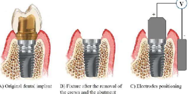
The therapeutic signal is delivered between two electrodes (realized in metallic biocompatible material): an active electrode, screwed to the implant fixture (in order to make a good electrical connection), and an electrode of return (also called neutral or passive electrode), put in contact with the gingiva, as illustrated in Fig. 5 C).
A single treatment entails five electric current bursts; in this way, the whole duration of the treatment (included the pauses between two delivered bursts) is of about 2 minutes.
The treatment is given under local anaesthesia and sometimes antibiotics and/or anti-inflammatory drugs are administered to the patient in order to enhance the therapeutic effect [35], [68].
Figure 5. Electrodes positioning: after having removed the crown and the abutment (B), the active electrode is screwed into the fixture, while the neutral one is put in contact with gingiva (C)
In case of particularly severe pathology, the treatment was repeated, up to a maximum of three times.
The implants included in the therapeutic treatment were placed in different positions (i.e. to replace molar, premolar, canine or incisor teeth), as reported in Fig. 6. The number of treated implants per year is reported in Fig. 7.
Figure 6. Distribution of the positions of the treated implants
The success of the therapy was evaluated by observing the colour of the gingiva, by evaluating bleeding and suppuration, by measuring the probing depth of peri-implant pockets and by means of x-rays imaging, in order to measure the bone height around the implant. Such diagnostic instruments are those of a typical peri-implantitis diagnosis [28].
2.1.2. Results
81% of the implants (i.e. 66), corresponding to 84% of the patients, were successfully treated by Dr. Tricarico in his dental office. Follow-up data considered in this research are related to 2002-2015 years.
In the follow-up checks, neither bleeding nor suppuration from the peri-implant soft tissues were observed. In addition, the gingiva showed neither oedema nor redness. So, it is possible to state that none of the inflammation symptoms were present. In Fig. 8 there is an example of images showing the gingiva conditions before and after the treatment.
Figure 8. Example of gingiva conditions before the therapy: A) with suppuration, B) with deep gingival pockets and C) with bleeding on probing; and after the therapy: D) healthy gingiva (no inflammation)
As regards the hard tissues, in order to prove the success of such therapeutic methodology, x-ray images were examined. They show that the peri-implant bone healed after the therapy and the bone resorption was arrested (not more than 0.2 mm per year, which can be considered not pathologic [21]); in some cases, it was possible to note also a phenomenon of peri-implant bone regeneration. In this regard, an example of x-ray images before and after the therapy is reported in Fig. 9; it is possible to observe that the bone has completely regenerated after the therapy, allowing the dental implant to recover its stability.
Figure 9: Example of x-ray image of an implant in three different moments: A) before the therapy, B) 1 month after the treatment and C) 8 months after the treatment
The unsuccessful cases (i.e. 19% of the implants, corresponding to 16% of the patients) were linked to very particular conditions or concurrent diseases: chemotherapy, serious aenemia or significant horizontal/vertical bone reduction, hematologic diseases and metabolic disorders. The critical aspects just mentioned will be considered as exclusion criteria for the therapy in the future, so that the success rate will probably be higher.
2.1.3. Discussion and conclusions
The proposed radio frequency current-based therapy for peri-implantitis can be considered among electric treatments and electromagnetic stimulation (whose beneficial effects are described in Paragraph 1.3).
Such trial permitted to obtain information about the safety and the efficacy of the adopted treatment. No complications occurred: the treatment sessions were fast, painless and the benefit for the treated patients was immediate, allowing to functionally recover dental implants otherwise fated to be removed.
As stated in Paragraph 1.3, the main effects of electromagnetic radiation are to inhibit bacteria, to increase bone formation, to positively remodel bone and to reduce inflammation. All these were verified in this clinical trial and allowed to successfully treat peri-implantitis cases, eliminating suppuration, stabilizing the bone level and promoting its regeneration, besides healing the inflamed soft tissues.
So, the adopted approach showed promising results, even more if we consider the unsatisfying outcomes achievable by means of standard therapies [35], [44].
It is now of interest to broaden the present clinical trial, by getting dragged not only Italian but also foreign dentistry and implantology experts, so as to obtain a larger sample to be evaluated.
As it will be described in the Appendix, a prototype of a specific device for peri-implantitis treatment (named PeriCare®) is being developed (the present therapy for peri-implantitis has already been patented) and it will be used for a wider multicenter clinical trial. This would permit to optimize the treatment parameters, both in terms of therapeutic doses and of used instrumentation (e.g. the electrodes shape). In addition, it could be possible to obtain further indications also on the methodologies applied to quantify the pathology
severity; in fact, during the present PhD research project, bioimpedance measures have been evaluated as a means to detect inflamed tissues and they can be useful also to assess the bone level (bioimpedance measurements will be described in detail in Chapter 3).
2.2. Electrical characterization of the therapeutic device
Endox® Endodontic System is a device used in endodontic therapy since the late 90s [80]. According to the standards of IEC 60601 published by the International Electrotechnical Commission, it is a Class I device (in fact it is a hand-held surgical instrument) of type BF (since there is a conductive contact with the patient) [87]. According to the European directive 93/42/CEE (imposing the obligation of CE marking for products sold within the European Economic Area [88]), this device is of class IIb, which means that a notified body had to do determined inspections during the realization phase [89, p. 42].
Figure 10. Endox® Endodontic System
It is in compliance with the regulations EN 60601-1 (Medical electrical equipment – Part 1: General requirements for basic safety and essential performance), EN 60601-1-2 (Medical electrical equipment - Part 1-2: General requirements for basic safety and essential performance - Collateral Standard: Electromagnetic disturbances - Requirements and tests) and EN 60601-2-2 (Medical electrical equipment - Part 2-2: Particular requirements for the basic safety and essential performance of high frequency surgical equipment and high frequency surgical accessories).
This electromedical device has a rating power of 110 W on a resistive load of 1000 Ω, for a duration of 140 ms. Its working frequency is equal to 312.5 kHz.
Endox® has two stages application: the former is the root canal length measurement to localise the radicular apex (done in Direct Current - DC - with a 9 V battery, sometimes causing an itching sensation due to the direct current passage), while the latter is the root canal treatment (also known as “devitalisation”), consisting in pulp removal, canal cleaning, disinfection and sealing. The power of the treatment can be regulated depending on the tooth type; different levels are available: incisor, canine, premolar, molar and molar plus boost (that is, ever higher than molar option).
Such a system is more powerful than the traditional methods for the root canal treatment [90], since it allows to efficiently reduce bacteria, to remove pulp residues not only in the
main canal but also in lateral canals and dental tubules (barely reachable mechanically), to avoid excessive pain and to save time. The effectiveness of the treatment was proved by means of Reflection Electron Microscope (REM) and histological analysis; neither thermal effects nor other damages to the surrounding tissues were observed [91]. However, proper cleanliness and optimal efficacy are reached only after the conventional canal preparation [92]. Finally, literature results about the antibacterial effectiveness (compared with conventional irrigation protocols, e.g. with sodium hypochlorite) in the endodontic treatment are controversial [93].
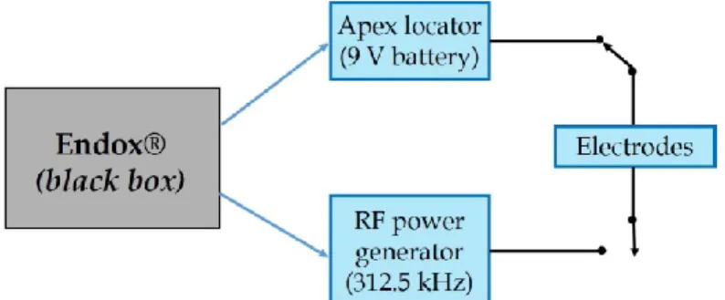
Endox® scheme is not known, so it is possible to consider it as a black box (Fig. 11) with two different functions, that is, the measurement of the canal length (by means of a DC electric apex locator, which is actually been largely overtaken [94]) and devitalisation (by means of a Radio Frequency - RF - current).
Figure 11. Endox® scheme: black box with two different functions, that is the measurement of root canal length (i.e. apex locator) and treatment (i.e. Radio Frequency - RF - power generator)
Both the measurement and the therapeutic signals are supplied between an active electrode (which is a fine surgical stainless steel needle, acting as the electrode, inserted in the open root canal) and a passive one, cylindrical, held in the patient’s hand, suggesting an unbalanced scheme for the circuit representation.
As said in the introduction of this chapter, positive side effects of such signals have been noticed in tissues surrounding the treated tooth root, beyond the expected ones of the mere endodontic treatment, so that a research project to better understand the underlying mechanisms has been started.
The first aim was to electrically characterize this medical device, in order to obtain an equivalent circuit (according to Thevenin’s theorem [95]), which can be used to numerically simulate the therapy and consequently to study the effects on biological tissues.
2.2.1. Materials and methods
In order to better understand the working principle of Endox® device, it is necessary to electrically characterize it. The simplest way to do it consists in the computation of the
Figure 12. Thevenin's theorem principle scheme: any black box containing current/voltage sources and resistors can be replaced by a series connection between an equivalent voltage source (Vth) and an
equivalent resistance (Rth)
The equivalent voltage source is the open-circuit voltage at the network terminals, while the equivalent resistance is that observable at the network terminals A-B when all the ideal voltage sources were replaced by short circuits and the ideal current source by open circuits (i.e. when all the independent sources are deactivated).
This theorem also applies to Alternating Current (AC) circuits, consisting of reactive and resistive impedances. The main assumption is that the electric network is linear, but actually many circuits are linear only over a certain range of values and this is a limit of such a technique. Performed tests allow us to assume circuit linearity during the RF burst generation in the present work.
To obtain the Thevenin equivalent circuit of the device, the scheme reported in Fig. 13 can be used.
Figure 13. Thevenin electrical circuit and measurement resistor (R)
The computation of the characteristic parameters Vth and Rth is based on the Root Mean
Square (RMS) values of the voltage V, measured on the load R for different values of the measurement resistor R. Resistors were used because at this frequency the prevailing conduction mechanism is the conductive one (this was verified by comparing σ with ωε and, so, by evaluating conduction and displacement current).
The circuit can be considered as a voltage divider and so described by the Eq. 1:
![Table 1. Thevenin circuit parameters for the different power levels Power level V th [V] R th [Ω] Incisor 435 392 Canine 500 495 Premolar 435 398 Molar 455 408](https://thumb-eu.123doks.com/thumbv2/123dokorg/2969054.27155/50.892.303.633.212.362/table-thevenin-circuit-parameters-different-incisor-canine-premolar.webp)