© Faculty of Mechanical Engineering, Belgrade. All rights reserved FME Transactions (2018) 46, 489-496 489
Received: September 2017, Accepted: April 2018 Correspondence to: Ph.D. Eng. Ana Pavlovic
Dept. of Industrial Engineering, University of Bologna Viale Risorgimento 2, 40136 Bologna, Italy
E-mail: [email protected] doi:10.5937/fmet1804489K
Joseph J. Kakkassery Assistant Professor Madras Institute of Technology, Anna University, Chennai, India V. Arumugam Associate Professor Madras Institute of Technology, Anna University, Chennai,
India K. Saravanakumar Researcher Madras Institute of Technology, Anna University, Chennai, India S. Durga Researcher Madras Institute of Technology, Anna University, Chennai, India C. Santulli Associate Professor Università degli Studi di Camerino
Ascoli Piceno, Italy A. Pavlovic Researcher Alma Mater Studiorum University of
Bologna, Italy
Residual Strength Estimation and
Damage Characterization by Acoustic
Emission of Drilled Thermally
Conditioned Fiberglass Laminates
Structural components of composite materials in aerospace industries are assembled using fasteners, installed by performing cutting processes, such as drilling, on the material. In composites, this is considered particularly critical, because delamination due to mechanical stresses and fiber/resin pullout may be facilitated during cutting, so that the structural integrity of composite laminates may be affected. Acoustic emission (AE) technique is employed to monitor the failure modes and damage mechanism of drilled composite materials, while in an attempt to improve the strength of the composites, thermal conditioning has been applied. This paper investigates the residual performance of drilled unidirectional glass fiber reinforced plastic (GFRP) laminates subjected to various thermal conditioning methods. Thermally treated laminates underwent three-point flexural tests under AE monitoring to compare their residual strength with the untreated ones. The results clearly show that the thermal conditioning could be used as an effective method for minimizing delamination in GFRPs.
Keywords: Acoustic emission, Thermal conditioning, Flexural properties,
Delamination, Debonding.
1. INTRODUCTION
The research on composite materials have advanced extensively over the last few decades, resulting in widespread use of GFRP composites for aerospace and automobile structures, sporting goods and many other lightweight applications, because of their low density, acceptable cost, high strength and stiffness, chemical and corrosion resistance, and good fatigue tolerance that make them a substantial alternative to metals, alloys and also other families of reinforced composites [1-8].
The improvement in manufacturing and machining process is a continuous challenge in the field of composite materials, including GFRP. Even though composite components are normally produced to near-net shape, machining is often needed to accomplish tolerance requirements for the assembly needs. As Ravishankar et al report [9], drilling is often used to make holes for assembling different parts with screws, rivets and bolts. As in the case of metal parts and laminates [10], the evaluation of overall performance and damage tolerant properties for composite laminates with drilled cut-out holes or similar defects also represent a relevant aspect for safety design, evaluated by Abrate et al, especially to avoid the occurrence of failure at low loads [11-14]. Delamination, fiber
pull-out, interlaminar cracking are the most frequently defects in composites, produced following thermal damage due to drilling, as demonstrated in different literature [15-17]. Among these, delamination is predominant, which takes place as separation of the various laminate layers due to localized bending at the in-situ point of drill contact.
It needs to be noticed that most studies on drilling effect on laminate performance and damage, concern carbon fibre reinforced composites. In practice, most studies on fiberglass concentrated on modelling, for example by torque and thrust, their behavior under drilling [18]. Shyha et al [19,20] observed that the drilling-induced delamination may occur on both sides of the laminate, hence at the entrance and at the exit of the drill bit from it: the two external layers are considered the most affected by this problem, which can lead to deterioration of components’ properties and performance. This can be controlled by reducing thrust forces during the drilling process, a possibility which is widely influenced by feed rate levels. Rawat et al [21] observed a substantial reduction in fiber-matrix interface shear strength, due to elevated temperatures during drilling, followed by matrix cracking and fiber pullout. According to Wong et al [22, 23], in the aerospace industry, approximately 60% of different components were reported to be rejected because of delamination and hole quality problems. A few studies by Kim et al [24, 25] have concluded that the thrust force plays a vital role in controlling delamination failure during drilling. According to Won et al [26, 27], the creation of pilot hole and the application of back-up
490 ▪ VOL. 46, No 4, 2018 FME Transactions
plates minimizes the delamination; also, drilling can be carried out at lower thrust forces using drill bits with smaller chisel edges.
Drilling CFRP composites caused particularly high and localized temperatures, as proved by Merino-Perez et al [28]. Heat-induced degradation of PEEK/ epoxy/graphite composites during short ageing periods on the flexural properties of the composite using 4-point bend tests was investigated by Kim et al [29]. They portrayed that early stage degradation accounted for the majority of the decay in the mechanical properties, but with modest effect on the weight loss. However, after prolonged exposure, a significant weight loss was observed, which had little impact though on the mechanical properties. The changes in environmental conditions such as heat and moisture cause a major impact in polymeric composites. Lifetime performance of polymeric composites is affected due to prolonged exposure to thermal and moisture expansion. The decrease in interlaminar shear strength (ILSS) value is predominant at higher conditioning temperatures. The coalescence of hydrothermal forces and residual stresses are sufficient to induce the failure of laminated composites and thus should be considered in damage-tolerant design and lifetime prediction, as it was concuded by Choi et al [30]. According to Favre et al [31], thermal exposure will induce an ageing of the matrix, mainly due to its oxidation, which is a non-negligible effect in thermal cycling, resulting in the matrix micro-cracking between plies. The effects of space environmental conditions on several carbon/epoxy composites have been studied by Seehra et al [32]: the study concluded that the mechanical properties remained unchanged after the exposure. However, when tested at low temperature, a slight decrease in strength was revealed. The behavior of graphite/epoxy composite materials subjected to thermal cycling was studied by Shin et al [33]. In this study, they measured a noticeable decrease in strength and stiffness of the composites after exposure, decrease which became more severe with the increasing number of thermal cycles: the properties that were affected at an earlier stage by thermal cycling were notably transverse flexural strength and stiffness.
Acoustic emission (AE) is defined as a transient elastic wave generated by the rapid release of strain energy within the material. Hamstad et al [34] suggested a basic principle, which make worthy pursuing AE evaluation of materials: during loading, damaged specimens produce a higher amount of AE (more signals of higher amplitude) than the undamaged ones. Stage-by-stage approach has been carried out to characterize fiber failure modes, beginning from a single carbon fiber composite which illustrated that the frequencies of AE signals virtually remain unchanged irrespective of the propagation distance between the AE source and sensors were studied by Ni et al [35]. The dominant frequency content of the sub-classified failure modes such as matrix cracking (90-110 kHz), delamination (130-200 kHz) and fiber failure (250-280 kHz) have been particularly investigated for GFRPs in recent studies by Asokan et al [36] and Christopher et al [37]. Bussiba et al [38], in particular, examined the
damage accumulation profile in terms of AE parameter such as counts rate and cumulative counts by using frequency analysis.
The effect of fiber orientation and the predominance of the different failure mechanisms in GFRP laminates using frequency and parametric analysis has been studied by Arumugam et al [39]. Liu et al [40] worked on discrimination of different failure mechanisms of carbon fiber/epoxy specimens by using the combination of AE parameters, such as amplitude, cumulative counts, and energy.
In this work, the influence of thermal conditioning on the residual flexural strength of drilled GFRP laminates was investigated and damage modes were characterized using acoustic emission (AE). The specimens were conditioned at the temperature of 600C for various thermal cycles in multiples of 5 up to 30 cycles, which were later drilled and subjected to three-point flexural testing.
2. EXPERIMENTAL PROCEDURE
2.1 Materials Preparation and Flexural Testing Monitored using Acoustic Emission
Unidirectional GFRP laminates were fabricated by hand lay-up technique. This method consists of impregnating a layer of stitch-bonded glass with a mixture of epoxy resin (LY556) and hardener (HY951) by the aid of rollers, successively applying it to a mold surface. Then the laminates were allowed curing at room temperature. The stacking sequence consists of [00]
16 yielding a total thickness of 4:2(±0.1) mm. Flexural test specimens were cut according to the ASTM D790-03 standard from fabricated unidirectional laminate using water jet cutting machine and are shown in Fig. 1 (a & b). Each flexural test specimen had planar dimensions 150x25 mm and was subjected to three-point flexural loading (support span = 120 mm) using a Tinius Olsen H100kU Universal Testing Machine, shown in Fig. 2, equipped with a 100 kN load cell. The crosshead testing speed was set to 1 mm/min. An eight-channel AE system, supplied by Physical Acoustics Corporation (PAC), was used to monitor AE data continuously, with a SAMOS E3.10 data acquisition system using sensors with a broadband of resonance (10 kHz – 2 MHz), with 40 dB pre-amplification and a 45 dB threshold.
2.2 Thermal Conditioning
After ensuring visually that the flexural test specimens were dried, they were introduced into a hot air oven, in which they were conditioned at a temperature of 600C. The temperature was raised from room temperature (20°C) to elevated temperature (60°C) and then vice versa with a minimum dwell time at each of the two of 10 minutes, as prescribed by IEC 61215:2005 standard. The transition from low to high temperature occurred in an average time of approximately 30 minutes, so to ensure that the slope of the temperature rise curve was in the region of 80°C/h, hence lower that 100°C/h, which is the maximum value prescribed by the above standard.
FME Transactions VOL. 46, No 4, 2018 ▪ 491
Epoxy systems used for this study have a minimum glass transition temperature (Tg) around 850C, as from indications provided by the manufacturer. Hence, thermal conditioning temperature of 600C was well below Tg. Subsequently, the specimens were exposed to the thermal treatment with different number (5, 10, 15, 20, 25, and 30) of thermal cycles. No substantial change in geometry or weight of the specimens was observed as the consequence of the thermal cycles.
Figure 1. Flexural samples (both surfaces, drilled and undrilled)
Figure 2. Flexural test specimen with each AE sensor positioned at 40 mm from the center
2.3 Drilling
The thermally treated and untreated specimens were subsequently categorized into two groups: drilled and undrilled. A 8 mm hole was drilled in the center of the unidirectional specimens using a Dremel high-speed tool. The specimens were supported on a back plate to avoid initial push-down delamination during drilling.
3. RESULTS AND DISCUSSION
The influence of thermal conditioning on drilled and undrilled unidirectional glass/epoxy composites was experimentally investigated by subjecting to flexural testing under acoustic emission monitoring. The failure mode has been characterized based on peak frequency analysis data obtained from AE data acquisition system.
3.1 Drilling behavior and acoustic emission characteristics
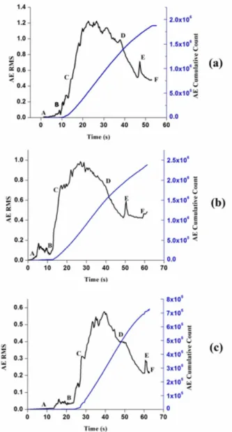
Figure 3 shows AE Root Mean Square (RMS), which is the strength of the signal integrated over 1 second, vs. time plot for thermally treated and untreated specimens. For the sake of more detailed observation of the drilling process, this was divided into five phases: contact (A-B), penetration initiation (B-C), steady penetration (C-D), penetration with lower thrust (D-E), and finally, exit (E-F). These were compared with the AE RMS values observed.
Figure 3. AE RMS and AE Cumulative Counts vs. Time, for specimens: (a) Untreated (b) Treated for 5 Cycles (c) Treated for 30 Cycles
During the first stage (A-B), a rapid increase in AE RMS was observed because of drill bit contact with the specimen while initiating the penetration. From (B-C) the complete steady penetration occurs through the cutting stage of the specimen, which is the proper drilling phase.
Delamination occurs because of exceeding the axial thrust force during drilling, which is greater than the interlaminar shear strength of the remaining plies.
High amounts of energy were released because of delamination, which was detected by the AE sensor; as
492 ▪ VOL. 46, No 4, 2018 FME Transactions
a result, a rapid increase in the RMS value was observed in (C-D) phase. AE RMS value remains at a constant low level, dropping from the peak in (D-E). Friction between rotating drill bits and the walls of the hole induces low-level energy signals which were observed in the final phase (E-F).
According to the above plot, initiation time of AE RMS value has been delayed for the specimens that were thermally treated for 30 cycles with respect to the 5 cycles and untreated specimens: this is clearly observed in the region of initial contact (A-B). The delay in RMS peak was also evident in the following two phases. Here, a rapid increase in the RMS value occurs, whose extent appears more limited though with increase in the number of thermal conditioning cycles. This leads to the conclusion that thermal conditioning reduces delamination. Also during (D-E) & (E-F) stages, AE RMS value was observed to decrease considerably with the increase in number of thermal cycles applied to the material. Therefore, acoustic emission can be used as a promising technique for classification of AE signals during the drilling process and to characterize the failure mechanisms in advance.
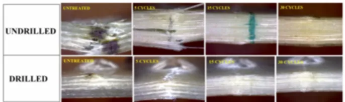
Figure 4 shows microscopic photographs of specimens with drilling-induced delamination around the holes. The delamination on the front side was observed to be peel-up, while push down delamination was revealed at the back side of the specimens. The uncut fiber and spalling are clearly visible inside the drilled holes. The delamination region is considerably decreasing in thermally treated specimens confirming the influence of conditioning on the polymer composites. Change in color of the specimen surface was also noted, because of oxidation.
Figure 4. Microscopic images of drilled zones in specimens
3.2 Flexural behavior and acoustic emission characteristics
Three-point flexural test was performed to determine the flexural strength and residual strength of post-drilled and thermally conditioned specimens alike. Various damage modes have been investigated. The dominant failure mode, delamination, induced during the post-drilling flexural test was considerably reduced in thermally treated specimens than untreated specimens.
Figure 5 shows ultimate flexural strength at various number of thermal cycles for undrilled and drilled specimens. For undrilled specimens, significant improvement up to 20 thermal conditioning cycles was observed. This confirms that in general terms thermal conditioning cycle enhances bonding between fiber and matrix [41, 42]. The maximum relative improvement is obtained between 0 and 5 thermal conditioning cycles, which implies that the only thermal conditioning process produces benefits
already. For 25 and especially 30 thermal conditioning cycles, however, a progressive decrease of laminate flexural strength is measured. An explanation of this trend can be the fact that prolonged exposure to elevated temperature causes matrix oxidation, which was observed also from the microscopic images, resulting in cracking and surface degradation. Drilling results in a loss of flexural strength around 15% for unconditioned laminates. Also for drilled laminates conditioning up to 20 cycles increases their flexural performance therefore is beneficial, no longer so for 25 and 30 cycles. It needs to be pointed out though that the maximum recovery of drilling damage is obtained at 15 conditioning cycles.
The phenomenon of damage in various specimens during flexural testing was characterized by different stages, such as damage initiation, damage propagation and occurrence of rupture. Initially, at the early stage referred to the elastic region, the structure deforms without any formation of cracks and no AE signals were acquired. The AE energy was very limited in this region and the equivalent rise angle shows slight peaks due to less significant damage formation in the middle of the test. As far as microcrack development is concerned, when increasing the applied force, these appear in the interfacial region, leading to damage propagation. The region can be easily visualized by initiation of AE activity with high emitted cumulative energies and rise angle with higher peaks than the first stage. As the damage progresses, macro-cracks are formed and they propagate along the interface region, with AE energy being released with maximum rise angle. AE energy recorded in this region shows a stepwise pattern in which each sudden jump of energy can be correlated to a sudden fracture energy release and can thus be attributed to macro-fracture events.
Figure 6 shows load vs. time plot during flexural tests, grouped with equivalent rise angle (ratio of rise time to amplitude) and cumulative energy for undrilled and drilled laminates. The increase in rise angle typically indicated fracture/cracking transition modes during loading [43]. From the figure, a mutual correspondence was observed between AE and flexural data. In particular, substantial AE activity starts much earlier for drilled than for undrilled laminates, as an effect of damage produced. In the case of drilled and unconditioned laminates, some AE activity is detected even before the laminate has reached its maximum flexural load, as can be observed from the step-like (and not quasi-hyperbolic) nature of the AE cumulative counts curve.
Maximum rise angle peak is measured in every case after the laminate has reached its maximum flexural load. In some instances, most part of acoustic emission activity is concentrated at the very end of the test, which suggests that substantial damage only occurs in the proximity of final collapse. This is particularly true for drilled laminates subjected to 5 and 15 cycles of thermal conditioning. In contrast, for drilled laminates subjected to 30 cycles of thermal conditioning, the rise angle peak occurs earlier to show that the laminates undergo a more gradual process of damage during plastic phase of flexural loading.
FME Transactions VOL. 46, No 4, 2018 ▪ 493
Figure 5. Flexural Strength for various numbers of cycles on drilled and undrilled laminates
Figure 6. Load, AE rise angle and cumulative counts vs. time for various numbers of cycles on drilled and undrilled laminates
Figure 7 shows microphotographs of thermally treated flexural tested specimen with and without drilling holes. It is observed that the delamination and fiber breakage was clearly visible from the damaged untreated and undrilled laminates. The appreciable reduction in delamination and fiber breakage was observed in thermally treated specimens. As thermal conditioning cycles increase up to 30, once again moderate color change at the surface of specimens was observed. This phenomenon occurs because of oxidation where the polymer undergoes mass loss, shrinkage resulting in initiation of spontaneous cracks causing degradation of fiber/matrix interface which reduces the flexural strength of composites at higher thermal conditioning cycles. The resistance to delamination and damage mechanism prevented in the end, for a limited number of thermal conditioning cycles, the occurrence of catastrophic failure. In practice, the dominant failure mode observed in thermally conditioned specimens was matrix cracking and this did not change as the effect of drilling, causing steady and delayed failure mechanism.
Figure 7. Microscopic photographs of undrilled and drilled laminates, conditioned or not with a various number of cycles after flexural tests
3.3 Failure modes characterization using acoustic emission
Acoustic emission can also provide information on the failure modes of composite that can be discriminated with sufficient accuracy by frequency analysis of AE signals which were acquired as the result of damage accumulation during testing. Consequently, every AE waveform signal has a unique characteristic, that is, its amplitude, duration and frequency content can be associated with the specific damage mechanisms, such as matrix cracking, debonding and delamination, and fiber failure which was studied by Pappas et al [44].
Figure 8 shows the peak frequency versus time plots for undrilled and drilled specimens exposed to various thermal cycles. In all cases, four different ranges of peak frequency were observed, such as 60-120 kHz, 150-200 kHz, 220-280 kHz, and 300-350 kHz, which can be related to matrix cracking, debonding, delamination and fiber breakage, respectively.
It can be observed that most AE activity detected in initial phases of flexural loading is correlated to matrix cracking and is in general terms more abundant in drilled than in undrilled laminates. Debonding and especially delamination–related AE events only take place at subsequent times during the test, whereas fiber breakage is typical of situations in which the level of maximum elastic strain has been exceeded and therefore the laminates undergo a significant plastic deformation. The main exception to this behavior can be observed in the drilled laminates conditioned with 30 thermal cycles where limited AE activity is observed therefore it can be suggested that only minor amounts of damage is necessary to lead to failure of the laminate and thermal stress is no longer beneficial. In contrast, it produces early fibre breakage in the material, as is obvious from the events’ distribution.
Figure 8. Peak frequency of AE events vs. time for undrilled and drilled laminates thermally conditioned or not
In the more holistic study over AE events distri– bution, reported in Figure 9, it can be also observed that
494 ▪ VOL. 46, No 4, 2018 FME Transactions
the percentage amount of matrix cracking events is rather casual in undrilled laminates. In contrast, matrix cracking events are consistently very high in drilled laminates, and especially when the number of thermal cycles amount to more than 15. A possible explanation is that obvious damage produced by drilling in the polymer matrix surrounding the hole is compensated up to a point from thermal cycling: in the case of lami– nates thermally conditioned with 30 cycles, matrix crac– king is so heavy that it unprotects fibre from breakage.
Figure 9. Percentage of AE events associated to different failure modes for laminates undrilled and drilled, conditi– oned with various numbers of thermal cycles
Finally, Figure 10 shows the microscopic photo– graph of cross-sectional view of the thermally treated laminates. The influence of thermal conditioning intro– duces surface flaws resulting in oxidation cracking causing degradation. Oxidation-induced cracks in unidi– rectional composites often initiate at fiber tips exposed at the surfaces. As the number of thermal conditioning cycles increase, spontaneous cracks arise within the oxidized layers at the surface of specimens. This effect of oxidative degradation causes the reduction in strength and load carrying capacity of the specimen.
Figure 10. Microscopic images of cross-sectional view of thermally conditioned laminates
4. CONCLUSION
In this study, the effect of thermal conditioning on the drilling behavior and residual strength of drilled unidirectional GFRP specimens was investigated. Drilled and undrilled specimens, thermally treated with different cycles, from 5 to 30, were then subjected to three-point flexural tests with real-time monitoring of acoustic emission (AE).
From the results, it can be suggested that thermal conditioning has considerably improved the residual strength of the drilled unidirectional GFRP composite laminates. The damage modes were observed to be generally decreased in thermally treated specimens because of removal of internal stresses. Microscopic images evidence the suppression of delamination and hindrance to failure mechanism in general terms.
As a consequence, matrix cracking turned out to be the dominant failure observed in thermally treated specimens, especially above 15 conditioning cycles,
where the positive effect on thermal treatment on flexural performance started to be minor, finishing to disappear for conditioning with 25 or 30 thermal cycles. Here, a slight decrease in ultimate load was observed due to prolonged exposure of conditioning time because of oxidation degradation. The microscopic images clearly evidence the delamination suppression and influence of oxidation [45].
A general consideration would highlight the effect of thermal conditioning on drilled laminates to avoid that matrix cracking around the hole would not result in early and progressive damage. This is valid until ther– mal conditioning does not result in excessive stress, and can really bring back the flexural performance of drilled laminates at levels approaching, within 10-15% loss, the level of strength of as-received laminates.
REFERENCES
[1] ASM Handbook, Composites. ASM International. vol. 21, 2001.
[2] Kaw, A.K.: Mechanics of composite materials. 2nd ed., Taylor & Francis, 2006.
[3] Chung, D.D.L.: Composite materials science and
applications. 2nd ed., Springer, 2010.
[4] De Paola, S., Minak, G., Fragassa, C. and Pavlovic, A.: Green Composites: A Review of State of Art. In: Proceeding of the 30th Danubia Adria
Symposium on Advanced Mechanics, Primosten,
Croatia, 25-28 September 2013 [ISBN: 978-953-7539-17-7]: pp 77-78.
[5] Hyseni A, De Paola S, Minak G, Fragassa C (2013) Mechanical Characterization of EcoComposites. In:
Proceeding of the 30th Danubia Adria Symposium
on Advanced Mechanics, Primosten, Croatia, 25-28
September 2013 [ISBN: 978-953-7539-17-7]: pp 175-176.
[6] Rasuo, B.: Experimental techniques for evaluation of fatigue characteristics of laminated constructions from composite materials: full-scale testing of the helicopter rotor blades, Journal of Testing and Evaluation (JTE), Vol.39, Issue 2, ASTM International, USA, pp. 237-242, 2011.
[7] Beaumont, P.W.R., Soutis, C., and Hodzic, A. (Editors): Structural integrity and durability of advanced composites: Innovative modelling methods and intelligent design, Woodhead Publishing - Elsevier, Cambridge, UK, 2015.
[8] Dinulović, M., Rašuo, B., Krstić, B., Bojanić, A.: 3D random fiber composites as a repair material for damaged honeycomb cores, FME Transactions, Vol. 41 No 4, pp. 325-332, 2013.
[9] Ravishankar, S.R., Murthy, C.R.L.: Ultrasonic imaging for evaluation of drill induced delaminations in composite laminates. In:
Proceedings of 14th Conference on non-destructive
testing, New Delhi 8-13 Dec. 1996, pp. 8–13.
[10] Heidary, H., Sadri, M., Karimi, N. Z. and Fragassa, C.: Numerical Study of Plasticity Effects in Uniform Residual Stresses Measurement by Ring-Core Technique. Journal of the Serbian Society for
FME Transactions VOL. 46, No 4, 2018 ▪ 495
Computation Mechanics. Vol. 11, No. 2, pp. 17-26, 2017. doi: 10.24874/jsscm.2017.11.02.02
[11] Abrate, S.: Impact engineering of composite
structures. Springer, 2011.
[12] Zureick, A. H., Nettle, T. A.: Composite materials:
testing, design, and acceptance criteria, ASTM
International, STP 1476, 2002.
[13] Suemasu, H., Ishikawa, T.: On failure mechanisms of composite laminates with an open hole subjected to compressive load, Compos. Sci. Technol, Vol. 66, No. 5, pp. 634–641, 2006.
[14] Zivkovic, I., Pavlovic, A., Fragassa, C. and Brugo, T.: Influence of moisture absorption on the impact properties of flax, basalt and hybrid flax/ basalt fiber reinforced green composites. Composites Part B, Vol. 111: pp. 148-164, 2017.
[15] Wern, C.W., Ramulu, M., Shukla, A.: Investigation of stress in the orthogonal cutting of fibre-reinforced plastics. Exp. Mech, Vol. 36 No. 1, pp. 33–41, 1996.
[16] Rao, G.V.G., Mahajan, P., Bhatnagar, N.: Micro-mechanical modelling of machining of FRP composites – Cutting force analysis. Compos. Sci. Technol, Vol. 67 No. 3–4, pp. 579–593, 2007. [17] Kastratović, G., Vidanović, N., Grbović, A., Rašuo,
B.: Approximate determination of stress intensity factor for multiple surface cracks, FME Transactions, Vol. 46, No. 1, pp 41-47, 2018.
[18] Langella, A., Nele, L., Maio, A.: A torque and thrust prediction model for drilling of composite materials, Compos. Part A Vol. 36 No. 1, pp. 83-93, 2005.
[19] Shyha, I.S, Soo, S.L., Aspinwall, D.K., Bradley, S.: Effect of laminate configuration and feed rate on cutting performance when drilling holes in carbon fibre reinforced plastic composites. J. Mater. Proc. Technol Vol. 210, No.8, pp. 1023–1034, 2010. [20] Shyha, I.S. et al.: Drill geometry and operating effects
when cutting small diameter holes in CFRP, Int. J. Mach. Tools Manuf Vol. 49, pp. 1008–1014, 2009. [21] Rawat, S., Attia, H.: Wear mechanisms and tool life
management of WC–Co drills during dry high speed drilling of woven carbon fibre composites, Wear Vol. 267, No. 5-8, pp. 1022–1030, 2009. [22] Wong, T.L., Wu, S.M., Croy, G.M.: An analysis of
delamination in drilling composite materials, in:
Proceedings of 14th SAMPE Technology
Conference, Atlanta, GA, USA, 1982, pp. 471–483.
[23] Stone, R., Krishnamurthy, K.: A neural network thrust force controller to minimize delamination during drilling of graphite–epoxy laminates, Int. J. Mach. Tools Manuf. Vol. 36 No. 9, pp. 985–1003, 1996.
[24] Kim, D., Ramulu, M., Doan, X., Influence of consolidation process on the drilling performance and machinability of PIXA-M and PEEK thermoplastic composites. J. Thermoplast. Compos. Mater Vol. 18, No. 3, pp. 195–217, 2005.
[25] Hocheng, H., Tsao, C.C.: Effects of special drill bits on drilling-induced delamination of composite materials. Int. J. Mach. Tools Manuf Vol. 46, pp. 1403–1416, 2006.
[26] Won, M.S., Dharan, C.K.H.: Chisel edge and pilot hole effects in drilling composite laminates. ASME J. Manuf. Sci. Eng Vol. 124, No.2, pp. 242–247, 2002.
[27] Tsao, C.C., Hocheng, H.: Effects of exit back-up on delamination in drilling composite materials using a saw drill and a core drill, Int. J. Mach. Tools Manuf. Vol. 45, No. 11, pp. 1282–1287, 2005. [28] Merino-Pérez, J.L, Royer, R., Ayvar-Soberanis, S.,
Merson, E., Hodzic, A.: On the maximum temperatures developed in CFRP drilling using uncoated WC-Co tools – Part I: The influence of the work piece constituents and cutting speed on heat dissipation, Compos. Struct Vol. 123, 2015, pp. 161-168.
[29] Kim, J., Lee, W., Tsai, S.W.: Modeling of mechanical property degradation by short term aging at high temperatures, Compos. Part B, Vol. 33, No. 7, pp. 531–543, 2002.
[30] Choi, H.S., Ahn, K.J., Nam, J.D., Chun, H.J.: Hygroscopic aspects of epoxy/carbon fiber composite laminates in aircraft environments, Compos. Part A Vol. 32 No. 5, pp. 709–720, 2001. [31] Favre, J.P. et al.: Ageing of organic matrix
composites at moderate temperatures - A first assessment, Proceedings of: 10th National Conf. on
Comp. Mat. (JNC-10), Baptiste, D. & Vautrin, A. (ed.), Vol. 1, pp. 205-214, 1996.
[32] Seehra, S., Benton, D., Rosen, J., Gounder, R.: Effects of space environmental conditions on graphite epoxy composites, SAMPE J Vol. 21, No. 2, pp. 18–23, 1985.
[33] Shin, K.B. et al.: Prediction of failure thermal cycles in graphite/ epoxy composite materials under simulated low earth orbit environments, Compos. Part B, Vol.31, No.3, pp.223-235, 2000.
[34] Hamstad, M.A. et al.: Correlation of residual strength with acoustic emission from impact-damaged composite structures under constant biaxial load, J. Compos. Mater Vol. 26, No. 15, pp. 2307-2328, 1992. [35] Ni, Q.Q., Iwamoto, M.: Wavelet transform of
acoustic emission signals in failure of model composites. Eng. Fract. Mech Vol. 69, No. 6, pp. 717–728, 2002.
[36] Asokan, R., Arumugam, V., Santulli, C., Barath Kumar, S., Joseph Stanley, A.: Investigation of the strength of the failure modes in GFRP laminates using acoustic emission monitoring, Int. J. Polym. Technol. Vol. 3 No. 2, pp. 57-65, 2011.
[37] Christopher, C.M.L., Sasikumar, T., Santulli, C. and Fragassa, C.: Neural network prediction of aluminum–silicon carbide tensile strength from acoustic emission rise angle data. FME Transactions, Vol. 46, No. 2, pp. 253-258, 2018.
496 ▪ VOL. 46, No 4, 2018 FME Transactions
[38] Bussiba, A.et al.: Fracture characterization of C/C composites under various stress modes by moni– toring both mechanical and acoustic responses, Carbon Vol. 46, No. 4, pp. 618–630, 2008.
[39] Arumugam, V. et al.: Effect of fiber orientation in uni-directional glass epoxy laminate using acoustic emission monitoring, Acta Metall. Sin (Engl.Lett.), Vol. 24, No.5, pp. 351–364, 2011.
[40] Liu, P.F. et al.: A study on the failure mechanisms of carbon fiber/epoxy composite laminates using acoustic emission, Mater. Des, Vol. 37, pp. 228-235, 2012.
[41] Arumugam, V., et al.: Ultimate strength prediction of carbon/epoxy tensile specimens from acoustic emission data. J. Mater. Sci. Technol, Vol.26 No. 8, pp. 725-729, 2010.
[42] Hsiao, B.S, Chen, E.J.H.: Transcrystalline inter– phase in advanced polymer composites. In:
Proceedings of controlled interphases in composite materials conference, Cleveland (OH), USA, p.
613–622, 1990.
[43] Rilem. Technical Committee 212-ACD. Acoustic
emission and related NDE techniques for crack detection and damage evaluation in concrete, 2010.
[44] Pappas, Y.Z., Kostopoulos, V.: Toughness charac– terization and acoustic emission monitoring of a 2-D carbon/carbon composite, Eng. Fract. Mech, Vol. 68, No. 14, pp. 1557–73, 2001.
[45] Rose, N., Le Bras, M., Delobel, R., Costes, B., Henry, Y.: Thermal oxidative degradation of an epoxy resin, Polymer Degradation and Stability Vol. 42, No. 3, pp. 307–316, 1993. ПРОЦЕНА ЗАОСТАЛОГ НАПОНА И КАРАКТЕРИЗАЦИЈА ШТЕТЕ АКУСТИЧНОМ ЕМИСИЈОМ БУШНИХ ТЕРМИЧКИ ОБРАЂЕНИХ ЛАМИНАТА СА СТАКЛЕНИМ ВЛАКНИМА Ј.Ј. Какасерy, В. Арумугам, К. Сараванакумар, С. Дурга, Ц. Сантули, А. Павловић Структурне компоненте композитних материјала у ваздухопловној индустрији састављене су помоćу причвршћивача, постављених поступком резања, као што је бушење, на материјалу. У композитима ово се сматра посебно критичним, јер се током сечења може олакшати деламинација због механич– ких напрезања и повлачења влакана /смоле, тако да се може утицати на структурни интегритет композитних ламината. Техника акустичне емисије (AE) користи се за праћење режима квара и механизам оштеćења композитних материјала, док се у покушају побољшања чврстоће композита примјењује термичко кондиционирање. Овај рад истражује преостале карактеристике ламината ојачаних стакленим влакнима (GFRP) који су подвргнути различитим методама термичког кондиционирања. Термички обрађени ламинати су под контролом AE подвргнути тестовима са три тачке како би упоређивали њихов заостали напон са необрађеним. Резултати јасно показују да се термичка обрада може користити као ефикасна метода за минимизирање деламинације у GFRP.