Full Terms & Conditions of access and use can be found at
https://www.tandfonline.com/action/journalInformation?journalCode=uarc20
International Journal of Architectural Heritage
Conservation, Analysis, and Restoration
ISSN: 1558-3058 (Print) 1558-3066 (Online) Journal homepage: https://www.tandfonline.com/loi/uarc20
Damage Assessment and Dynamic Characteristics
of Temples in Nepal Post Gorkha 2015 Earthquake
Eleonora Spoldi & Salvatore Russo
To cite this article: Eleonora Spoldi & Salvatore Russo (2019): Damage Assessment and Dynamic Characteristics of Temples in Nepal Post Gorkha 2015 Earthquake, International Journal of
Architectural Heritage, DOI: 10.1080/15583058.2019.1628322
To link to this article: https://doi.org/10.1080/15583058.2019.1628322
Published online: 24 Jun 2019.
Submit your article to this journal
Article views: 21
View related articles
ORIGINAL ARTICLE
Damage Assessment and Dynamic Characteristics of Temples in Nepal Post
Gorkha 2015 Earthquake
Eleonora Spoldi and Salvatore Russo
DCP, Dorsoduro 2206, 30123, IUAV University of Venice, Venice, Italy
ABSTRACT
The aim of this paper is to identify, also through micro tremor analysis and numerical analysis, the collapse’s mechanisms of the Nepalese wood-masonry monuments damaged by the 2015 seismic event that struck Kathmandu and its valley. The research analyses two case studies: The Radha Krishna and the Bhimsen Temples.
After a careful anamnesis based on visual inspection and hypotheses on the temple’s structural behaviour, a global dynamic ambient test (micro tremor) was carried out for qualitative char-acterisation of the structural system, residual stiffness and strengths.
First, numerical models have been calibrated on mechanical parameters present in literature. The difference between experimental results and numerical model values is higher than 100% in the Radha Krishna temple and 70% in the case of Bhimsen temple. Considering this results, the models were calibrated on the experimental results. The modal analysis shows important mixed effect of torsional and flectional mode in the case of the Radha Krishna temple while in the Bhimsen temple local effects prevail. The capacity curve of Radha Krishna temple shows behavior close to collapse at 0.26 g, while the Bhimsen temple presents important damage at 0.3 in Z direction and 0.23 in X direction.
ARTICLE HISTORY
Received 15 November 2018 Accepted 2 June 2019
KEYWORDS
Damage assessment; FE model; Gorkha earthquake; micro-tremor; Nepali collapse mechanism; Nepal temple; pushover analysis; tromograph
1. Introduction
Several monumental masonry buildings are found in the Kathmandu valley and they have been inscribed on the UNESCO’s Cultural World Heritage list since 1979, due to their extraordinary number of mostly religious monu-ments and heritage buildings (Department of Archaeology
2015; United Nations Office2013). Considering the cultural and religious value of most of these monuments, the gov-ernment of Nepal has recently estimated a Cultural Heritage Impact of approximately US$ 169 million after a major earthquake hit near Kathmandu, plus more than US$200 million for recovery (NPC2015; Shakya et al.2014,
2015). Natural hazards, especially earthquakes, have always characterized this region, producing damage to a large extent across the centuries (Maskey2015). Apart from the 1255 earthquake, which killed one third of the population in the Kathmandu valley, the first event in recent history occurred in 1833 (Mw 7.7). One century later (1934),
another event hit the area (Mw8.1) with strong effects on
both the population and buildings: 4296 fatalities across the country and with 66,382 collapsed buildings. The last severe earthquake occurred in 1988, but the lack of maintenance and the fast uncontrolled reconstruction amplified the
effects of the last one (Tonna et al. 2016). The recent Gorkha earthquake of Mw 7.8 has severely damaged
Nepalese cultural heritage structures. According to the survey report by the department of Archaeology in Nepal, 745 monuments in and around the Kathmandu valley were damaged by the earthquake.
This study presents an experimental investigation of two Nepali Pagoda temples damaged by the 2015 Gorkha Earthquake, namely the Radha Krishna temple in Teku, a small district of Kathmandu, and the Bhimsen temple in Patan Durbar Square. The non-destructive technique used is based on ambient vibra-tion and micro tremor. The aim of this research is the dynamic characterization of the two temples using the correlation of visible damage, experimental test and numerical models.
2. Nepalese temples and their vulnerabilities In general, the weary temples in Kathmandu valley are square in plan, with two or three tires. Large temples with two or more tires are usually constructed with two core walls surrounding the sanctum core (Tiwari2009). The foundation of existing temples has rarely been
CONTACTEleonora Spoldi [email protected] IUAV University of Venice, Dorsoduro 2206, Venice 30123, Italy Color versions of one or more of the figures in the article can be found online atwww.tandfonline.com/uarc.
studied in depth hence its condition is unknown. The foundations are often just as wide as the plinth plat-form itself and they appear as the masonry mat. This has led many observers, which were expecting a foundation in the pattern of stepped footings for the main walls, to suggest that tired temples have no foun-dation at all (Tiwari 2009). The visible portion of the plinth is made of bricks or stone, with the top of each step often paved with stone. In most cases stone is used as a kind of reinforced trim on the plinth and it is never a major structural part of the temples (Dangol 2011). The observation of existing temples with a high plinth shows that it is usual for the plinth mat to be built directly on the ground level or a thin layer of bricks. The huge plinth base massive foundation helps to elim-inate the earthquake risk associated with soft soils (Nienhus2003). The traditional construction of temple employs a load-bearing brick wall laid in yellow clay mortar along with a secondary timber frame. The tim-ber frame construction (like wall plates, corner posts and rafters) are connected by timber pegs and lap joint (Dangol2011). In the case of multi-tiered temples, wall thickness is not the same for every storey, reducing from the base storey to the top tower. The thickness of the wall ranges from 50 cm to 75 cm and are con-structed with three layers. Wall structure has always been built with three layers, the other face of the wall is made of fired clay bricks with smooth finishing and the inner face is made of fired bricks (Thapa 2011). Outer and inner face layers were not well connected with the middle core wall. Normally the middle core is filled with Ma-Apa bricks. The bonding mortar inside the massive walls is not visible from the outside but it has a very large influence on the structural strength and resistance of the temple (Shakya et al.2012). In many temples, yellow colour clay mortar, mud and more rarely lime-surkhi mortar is used (Ranjitkar2010). In the temple, the roof is one of the elements, which give it a unique appearance, not only because of its general form and repeated sloping surface, but also because of individual ornamental and symbolic elements attached to it (Bonaparte and Sestini2014).
In respect to the roofing system the temples can be divided into one-roof, two-roof, three-roof or five-roof. Similarly, according to the roof style, temples can be divided into either Pagoda style or Sikharas style (Korn
2014, 1976). The framework of the different peripheral Pagoda roofs at every floor of the temple consists of radiating rafters which are tied together by walls plates at the top and a horizontal beam at the bottom. This is again supported by inclined struts (Theophile and Ranjitkar1992). The traditional connection between the rafter and wall plate and between the rafter and horizontal
beam consists of two timber pegs inserted to brace the rafter against the horizontal member. Sikharas temples, like Radha Krishna, are generally covered in stone or masonry. They have a square plan and reach several meters in height. Often the covers are re-formed by woo-den rings inserted in the roof. Generally, the ground floor presents vertical and horizontal timber elements of Sal wood. The ring- beams, that runs along the perimeter of the masonry, allows a better distribution of loads along the masonry length, and they are connected to the col-umns inserted in the masonry.
The symmetrical design of the buildings is an impor-tant characteristic of the Nepalese temples. The sym-metrical design is generally less vulnerable to seismic load than the unsymmetrical design. Such a plinth may redistribute share forces throughout the structure, thus partly absorbing the impact of strong earthquake jolts (Wood et al.2017). Lateral forces of an earthquake are exacerbated by the top heaviness of the structure cre-ated by the heavy mass of the mud and tile covered roof (Shakya et al.2014).
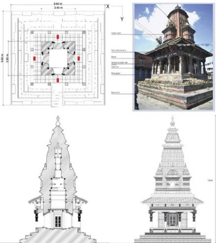
3. Description of the investigated monuments In this paper we chose to analyse the dynamic behaviour of two different Nepalese temples: The Bhimsen temple, a Pagoda style temple, and the Radha Krishna Temple, a Sikharas-style temple. The Radha Krishna temple (Figure 1) is a Sikharas-style temple located in Teku, a small district south of Kathmandu. It was constructed around 1850 by a brother of Janga Bahadur Rana. It was built to provide worshippers with a place where they could offer their prayers to Lord Shiva. The building is located on a masonry base. The base is approximately 2.5 m high and has a quadrangular plan (9 x 9 m). It has four levels and a staircase on the East front. The base reduces its plan dimensions regularly with each step. At the top of the base, there are 12 wooden columns near the masonry core connected to the base by the stone plinths. The structural system develops around a shrine that sits on the ground floor immediately above the base. The temple is built of unreinforced masonry and timber, but the main load bearing system is the brick masonry wall. The masonry wall on the ground floor has four openings, one on each façade. Vertical timber posts are located in the corners of the interior face of the wall. The external columns at ground level support a 260 × 260 mm timber beam, which in turn supports an exterior masonry. This masonry has a thickness of 380 mm approximately (Figure 1, ground floor plant). The building is 14 m tall (with base) and has a dome-like cover called“chhapra” with symmetrical masonry decorations on each side. The roofing system is made of an imposing masonry structure
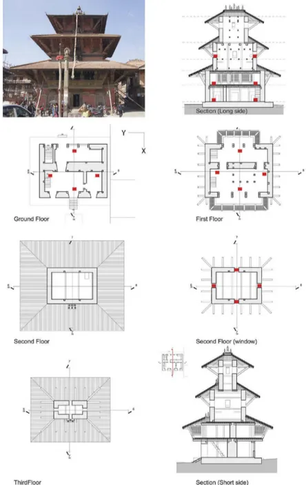
also reinforced with wooden beams. The temple has a square plan with a central cell (3450 mm × 3400 mm) with only one entrance to the North East side, since the others were covered with cement mortar masonry. The temple has a single floor composed of 90 mm × 110 mm wooden beams. The masonry on the ground floor is reinforced with wooden columns in the corners and an architrave system, also in wood, inside the cell. The wall thickness starts with 760 mm on the ground floor. The masonry walls are made of two classes of brick, a finishing brick for the exposed exterior faces called Dachi-Apa (Brando et al.2017) and a structural brick called Ma-Apa. The Bhimsen temple is a Degas pagoda temple (Figure 2) located in the North of the Patan Durbar square. The hypothetical date of construction is around the middle of the sixteenth century. The shape of the temple differs from the most common pagoda constructions because it has an asymmetrical rectangular plan; it does not have a central cell on the ground floor and it does not have a perimeter wooden colonnade. The Bhimsen temple has a base, made of brick and stone, (dimensions 10,60 m × 12,55 m) con-sisting of a 0.70 m high step East and a 0.27 m on West. This difference in height is due to the inclination of the ground. Access to the building is of the East and West fronts. The
temple is composed by three floors, the last of which is triple-height. The roofs have a decreasing dimension, and the building is crowned by an imposing bronze bell. In section, the roofs are not arranged in axis with the internal floors (Figure 2). The pitches are covered by a layer of mud and tiles that rests on a secondary wooden plank, supported by wooden main beams. The ground floor has a rectangular shape, two main cells, with entrances East and West and a smaller cell located to the North that serves as a storeroom. The perimeter walls have an average thickness of 60 cm, while the central spine wall has a total thickness of 1.50 m. The ground floor is connected to the first floor by two stairs, one external and one internal. Both are located near the Southern perimeter wall. The first floor has a central cell consisting of pillars and wooden beams. The top floor has a square free plan and the access is a removable staircase. The section shows a not continuous in height masonry with interruptions on each floor. The walls of the first and second floor rest directly on the beams that make up the floors. The building has a mud-bricks masonry reinforced by a wooden frame inserted in the same masonry. The main walls thicknesses are about 60 cm wide and the dimensions of the wooden pillars, inside the masonry, are 20 × 20 cm. The roofs are made of a wooden
reticular beams (roof beams and the struts) connected to the load-bearing masonry. Above the main beams of the roof there is a wooden plank. The inter-floor is also com-posed of a wooden structure (with East-West direction) composed of main beams very close together, wooden planks (with North-South direction), a layer of mud. The last covering is in marble. Other relevant structural ele-ments are the two wooden bow windows on the first floor of the East and West elevation. These are composed of wooden beams, struts and horizontal beams that make up the structural frame (Russo2010).
4. Damage assessment through visual inspection
The buildings under study were severely damaged by the 2015 Gorkha earthquake which hit Nepal with a magnitude of 7.8. To understand the actual damage level after having identified the construction phases, it was decided to pro-ceed to the survey’s cracks and collapses mechanism, obser-ving the entire structure globally and locally.
The Radha Krishna temple has an externally unda-maged roof, but the masonry on the ground floor has completely lost its static value due to the complete
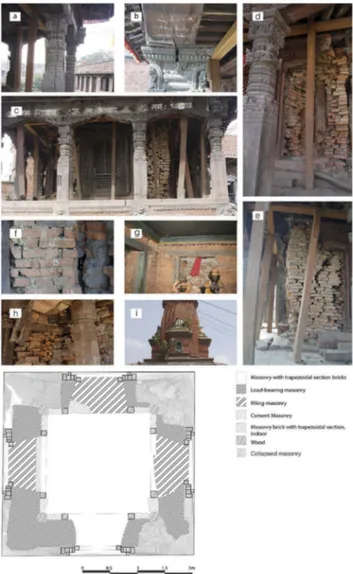
expulsion of the corners. The roof is 7 m tall, and it has a significant impact, in terms of weight, on the ground floor masonry. The building has not collapsed thanks yet to the wooden colonnade and the timber posts located on each side of the 4 openings. The recent infill of the 4 doors with cement mortar masonry had prob-ably a big role in preventing the full collapse of the structure. The ground floor consists of a timber colon-nade that had a good response to the action of the earthquake, although some columns are cracked and some architraves present a horizontal displacement. The structure showed the highest level of damage in the corners. The damage in the piers seems to be related to a lower quality of masonry in the elements. The piers do not show cracks but rather a totally dis-tributed disintegration. The extension of material loss is shown inFigure 3(damage survey): the corners should be filled with masonry but the hatched areas shows that only a small portion of the original material remains. The damage indicates that cohesion between bricks in the masonry is very low, almost inexistent. It is because of the lack of integrity that the piers suffered severe damage. In detail, it was possible to observe that the colonnade has responded positively to the horizontal stress of the earthquake despite eight columns appear cracked and 4 columns need replacement (Figure 3a, b). The masonry of the ground floor completely col-lapsed in the four corners, (Figure 3c) shows inside a reinforcement in wood that appear damaged or miss-ing a proper support on the ground (Figure 3d).
The windows are as high as the ground floor and have played a fundamental role in the dissipation of the energy induced by the earthquake. Currently, they pre-sent an out of plane mechanism but they are still able to support the completely cracked masonry behind them (Figure 3e). We can assume that the masonry has completely lost its function and the structure is sup-ported by the elements wood (colonnade, architraves, masonry interior columns). The visible mud mortar joints are 1.5–2 cm thick and the bricks have different dimensions and they are not positioned in a regular way (Figure 3f). Successive interventions of punctual consolidation without an overall and unitary strategy are present. Observing the masonry of the ground floor from the inside it is possible to see on each side wooden architrave systems inserted in the walls in correspon-dence with the external wooden windows (Figure 3g). Also, these wooden reinforcements helped dissipate the horizontal dynamic action. The architraves that make up these systems are inflected and the wall beneath them is cracked. Horizontal reinforcing wooden ele-ments were observed between the architrave systems, placed on the inside face of the masonry, and the
external wooden openings (Figure 3h). The presence of vegetation is also an indication of the maintenance absence (Figure 3i).
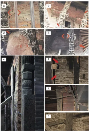
The Bhimsen Temple was slightly affected by the earthquake of 2015 compared to other buildings in Patan Durbar Square. The temple is located on a base that has not reported any damage and overall the struc-ture has been slightly damaged but it is not about to collapse. Globally, the most obvious damage is visible at the point of contact between wood and masonry ele-ments. This is influenced by the different vibrating way of these materials and their elastic characteristics. According to the external visual inspection, the temple presents diagonal cracks that end in the direction of the wooden frames or at the point of contact wall-floor-roof. Lateral sliding of the bricks near these cracks is also
Figure 3.Global and local damage survey of Radha Krishna Temple. a, b) Cracked columns, c) ground floor masonry, d) wooden reinforcement, e) out of plane mechanism, f) masonry detail, g) architrave system inserted in the wall, h) wooden reinforcement detail, i) presence of vegetation as indication of the maintenance absence.
visible. More specifically, there are diagonal cracks with a horizontal sliding of the bricks. (Figure 4a). This type of cracks are visible at the point of contact between wood and masonry in all building levels. There are twice cracks visible around the wooden windows, and in addition to the cracks, a detachment is visible between the timber and the masonry, caused by the difference in strength and elasticity of the two materials and by the presence of a vacuum in the masonry (Figure 4b). Some corner expul-sions, with diagonal cracks, are mainly visible on the second floor. The cracks are visible along the mortar joints and no cracked bricks are visible. It must be remembered that this type of brick is used as a covering and it is not possible to view the real condition of the load-bearing masonry (Figure 4c). The Figure 4dstill shows a diagonal vertical crack along the mortar joints, at the clamping point of the corner, probably caused by an incorrect position of the corner bricks. If on the outside the visible damage is limited to some cracks, the damage level of the internal structure is much higher. TheFigure
4eshows an evident masonry swelling (about 10 cm) with frame detached. This damage is relative to the wall on the first level. Important cracks along the mortar joints are visible on the top floor (Figure 4f). There are also some detachments between wooden and masonry portals (Figure 4g).Figure 4h shows the separation between the timber pilaster and the timber beam, inserted in the masonry of the last level. The northern façade is the most cracked elevation and the damage reported included twice cracks on the first floor, diagonal cracks and lateral sliding of the bricks on the second floor, separation between the masonry and wooden the windows.
5. Micro tremor analysis
For the dynamic modal characterization of the struc-tures and the subsoil, we used the Tromino® device that optimizes the measurement of the micro tremor in the frequency range between 0.1 and 200 Hz. An important part of the damage related to the effects of earthquakes in buildings is associated with the amplification of seismic waves caused by the site effect (Gentile and Saisi 2007). The performs frequency spectral ratio or HVRS (Horizontal to Vertical Spectra Ratio), is one of the most common approaches to determine this effect. This approach, proposed first in Nakamura (1989), and then by Nogoshi and Igarashi (1970) is based on the initial studies of Kanai and Tanaka (1961). The test, invented in Japan in 1970, is performed with a three-component seismometer. The tromograph software related to the Tromino allows to determine the site effect and use the well-known fast Fourier transform (FFT) to obtain related spectra (Chopra2015).
Generally, the environmental noise is divided into two categories: natural and anthropic. Very often, espe-cially in urban areas, this subdivision corresponds to different frequencies (Chopra 2015). At low frequen-cies, less than 1 Hz, the origin is essentially natural: marine waves, coast-tide interaction, wind, unstable meteorological conditions and thunderstorms. At high frequencies, above 1 Hz, the origin is mainly linked to human activities (traffic, industrial machinery). The H/ V technique allows to eliminate the effect of noise from the recordings as to obtain a stable curve with the resonance frequencies of the ground (SESAME Project
2004). The technique used to eliminate the effect of the underground site in the investigated structure is called Standard Spectral Ratio (SSR), while the analysis con-ducted to identify the vibration modes of the structure is the ratio between homologous Hi/H0 components
(vertical or horizontal), able to identify different modal shapes (Albarello and Castellaro 2011). The sampling frequency chosen for our buildings and base
Figure 4.Global damage survey of Bhimsen Temple. a) diag-onal crack, b) twice crack, c) masonry detail, d) vertical crack, e) masonry swelling, f) top floor crack, g) Wooden and masonry detachments, h) separation between timber pilaster and timber beam.
recording is 128 Hz, with a 16-minute duration. For the recordings, six velocimetry channels (sensitivity 51 mV) and three accelerometer channels were used. The traces were analysed with 20-second windows and 1% smoothing.
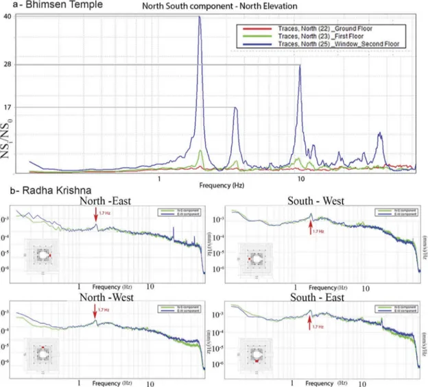
The instrument was placed on the ground, bases and in buildings. In the Radha Krishna temple, it was not possi-ble to make measurements with the Tromino® inside the building because it was not possible to reach the first floor for safety reasons. Therefore, we decided to limit our-selves to performing tests on the last level of the base (between two columns of the temple) to understand if the spectra were able to show the first frequency in the building. In the Bhimsen Temple, it was possible to record the structures by positioning the device in the window compartments on the second floor of each single front of the complex, on the first floor and ground floor. In this case, we used the SSR technique to analyse the recordings. It is possible to observe how the horizontal components present greater amplitudes. The experimental investiga-tions conducted with the tromograph in the Bhimsen Temple (Table 1) allowed to identify the average peak frequency of the investigated walls (1.9 Hz X direction, 1.6 Y direction,Table 1green rectangle). This difference in value in the two directions is influenced by the rectangu-lar shape of the building plan. In particurectangu-lar, the shorter side (X direction) has higher frequencies, while the longer side (Y direction) has lower frequencies (Russo, Liberatore, and Sorrentino2018). It was possible to record the same first peak frequencies both in the South and North fronts and in the East and West fronts. Another information that could be deduced from the recordings with the Tromino® is that globally the amplitudes in the graphs between homologous components tend to decrease with increasing peaks. The only exception was reconfigured in the northern front (Table 1, red rectangle,
Figure 5a) where the third natural frequency has a width greater than the second. It was also observed, thanks to the visual inspection, that the northern front is the most damaged front. The current arrangement of the sensors did not allow for torsional effects. However, the picture of the damage has shown that the Bhimsen Temple does not present clear torsion phenomena.
In the case of the Radha Krishna temple, where it was not possible to place the device in the building, the Fourier amplitude spectra of velocity (device placed on the base) shows a peak. This cannot be a ground peak because it would present a different form, for example an ogive form, so we can hypothesize that the peak is the first frequency of the temple (Figure 5b).
6. Numerical analysis
The finite element method was chosen to study the struc-tural response of the Radha Krishna Temple and the Bhimsen Temple; the software used is ANSYS 17. Masonry walls were modeled as solids and most of the timber elements were simulated using beam elements with their specific cross section. ANSYS Solid65 (isoperi-metric tri-dimensional 8 node) elements were chosen to model the masonry walls. The ANSYS Solid 65 element is similar to a 3-D structural solid but with the addition of special cracking and crushing capabilities. The most important aspect of this element is the treatment of non-linear material properties. The beam and timber elements were designed as lines with 6 degrees of freedom using the finite element “Beam188”. Only in the Radha Krishna model, the boundary condition at the base of the timber columns was modelled as a combination of a fixed dis-placement in the horizontal plane and a non-linear spring in the vertical direction using the finite element “Beam188”. The spring is added to simulate the real behaviour of the pin inserted into a stone base, the pin can lift but it cannot go down. The boundary condition at the base of the masonry wall are showed inFigure 6. The roof’s mud and tiles cover was not considered in the model and its weight was applied directly to the rafters. The quality factor of the mesh is about 0.9 for almost all solid elements. A quality factor is computed for each element of a model (excluding line and point elements). FE Modeler’s Mesh Metrics feature provides a composite quality metric that ranges between 0 and 1. This quality metric is based on the ratio of the volume to the edge length for a given element. A value of 1 indicates a perfect cube or square while a value of 0 indicates that the element has a zero or negative volume. The Radha Krishna model presents 137,224 nodes and 104,848 ele-ments, while the Bhimsen Temple models presents 413,742 nodes and 328,731 elements. The masonry is modeled on the base of Willam Warnke’s concrete model (Table 2). This model allows the numerical calcu-lation to crack and crush. The material model for timber is based on a linear isotropic model. The isotropic model was chosen to provide simplicity to the model and, since the stress in the timber elements never reaches the plastic limit, it was thus accepted as a valid representation. The
Table 1.Experimental frequency of Bhimsen temple.
Frequency Amplitude Direction East— West North- South East West North South X 1,9 Hz 1,9 Hz 24 35 40 24 3,5 Hz 3,4 Hz 18 17 17 18 5,9 Hz 9,6 Hz 9 6 28 16 Y 1,6 Hz 1,6 Hz 37 25 24 22 2,99 Hz 3,04 Hz 17 14 12 13 4,8 Hz 4,8 Hz 13 11 7 8
Figure 5.A) Ratio between homologues component, Amplitude, North front, Bhimsen temple B) Fourier amplitude spectra of velocity, Radha Krishna Base.
analyses conducted on the two models are modal analysis and pushover analysis.
6.1. Modal analysis with data from literature
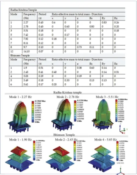
As suggested by Jaishi et al. (2003) and Shakya (2010) the modulus of elasticity of nepali mud masonry was taken as 800 MPa and the Poisson ration as 0.12. The masonry modulus of elasticity, that were used in the models (782 MPa), refers to the experimental diagnostic tests for the calibration of a FEM model of a Nepalese building described in (Parajuli et al.2010). TheFigure 7shows the results of modal analysis. The first modal shapes obtained are not pure but are an addition of flexions and rotations.
6.2. Modal analysis — experimental calibration model
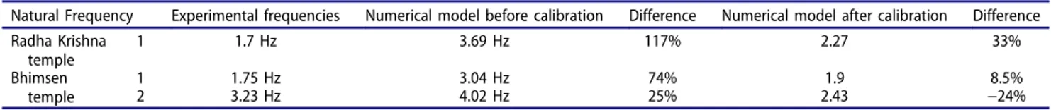
The difference between the experimental results and the computer model values is higher than 100% in the case of the Radha Krishna temple and 70% in the case of the Bhimsen temple (Table 3). Considering these results, it was clear that the model should have been refined to better represent the real behaviour of the temples, thus the modulus of elasticity was changed until a better cor-relation between experimental and computer model values was achieved (Russo2010). The calibration proce-dure was executed based on the assumption that the real material properties of mud masonry should have been within the range of values reported by Parajuli (Parajuli
2012) and the results obtained by UNESCO testing cam-paign on mud masonry. Parajuli suggested that the Modulus of elasticity for mud masonry should be around 274 MPa The models are calibrated using the modulus of elasticity 274 MPa. The models present all the detected and visible structural elements. To reproduce the masonry reinforced with wooden columns and diatones, the model is related to virtual beam-masonry composed material with perfect bound between them. The only uncertainty — about the structural timber elements-could concern some hypotheses on the roof design of the Radha Krishna temple that we could not inspect.
The model does not include the fair damage described in the“damage survey”. TheFigure 8 shows the results obtained after the model calibration.
6.3. Pushover analysis
The pushover analysis is a non-linear analysis whose goal is to simulate the response of the structure when it is subjected to an incremental horizontal load till the expected collapse. Since there is no load concentration on the floors (the temples are not accessible), the load, linear variable, has been evenly distributed throughout the whole structure proportionally to the mass. In the Radha Krishna temple the distribution is in agreement on the first and the second shape mode (Figure 8); in the Bhimsen temple the compatibility is much lower because the building does not mobilize beyond 40% of the mass.
For the Radha Krishna case study, a load of 0.5 g was divided in 300 increments of 0.001667 g and it was applied in X direction. The Radha temple is symmetric in both horizontal and vertical axis, so the load was applied only in one direction. The chosen control point is the top point of the structure. The amount of deforma-tion produced by an equal load increment remains the same at the beginning of the load stage (elastic range), however the appearance of cracks (nonlinear range) decreases the strength of the walls which results in a higher deformation. This phenomenon continues until the level of deformation in the building becomes too high (the walls have greatly weakened because of the accumu-lated damage). As shown inFigure 9, the Radha Krishna Temple would have a severe amount of damage (close to collapse) if hit by a 0.26 g earthquake. The last large Gorkha earthquake event had a maximum magnitude of 0.16 g and resulted in significant damage in the building. Numerical analysis shows also important shear cracks (Figure 9, maximum strain). These cracks are mainly developed on the ground floor.
In the real situation, when the temple was hit by the Gorkha earthquake, it did not develop important cracks but the masonry was simply disintegrated as if there were no mortar to connect the bricks. The Figure 9 shows a comparison between the maximum principal stains (numerical model) and the real damage. The value of 0.16481Max is very high for masonry, we remember that the model is related to virtual beam-masonry composed material with perfect bound between them.
In the Bhimsen temple model, a load of 0.5 g was divided in 300 increments of 0.001667 g and it was applied in X direction and Z direction. The capacity curve (Figure 10) shows that the building is close to collapse at 0.3 g in the Z direction, while in the X direction this occurs at 0.23 g.
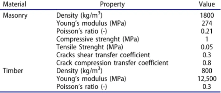
Table 2.Masonry and wood characteristic.
Material Property Value Masonry Density (kg/m3) 1800
Young’s modulus (MPa) 274 Poisson’s ratio (-) 0.21 Compressive strenght (MPa) 1 Tensile Strenght (MPa) 0.05 Cracks shear transfer coefficient 0.3 Crack compression transfer coefficient 0.8 Timber Density (kg/m3) 800
Young’s modulus (MPa) 12,500 Poisson’s ratio (-) 0.3
7. Discussion
The masonry of the Radha Krishna temple has been realized, with low quality materials with mud mortar that crumbles to the touch and bricks of different sizes positioned in an irregular way. A grey mortar is also
visible, probably cement. This allows us to hypothesize that local rehabilitation interventions have been carried out following the damage reported by the structure but there hasn’t been a total rehabilitation intervention. The visible damage in the Radha Krishna temple is more localized on the lower floors, where the greater
Table 3.Comparison between numerical and experimental frequencies.
Natural Frequency Experimental frequencies Numerical model before calibration Difference Numerical model after calibration Difference Radha Krishna temple 1 1.7 Hz 3.69 Hz 117% 2.27 33% Bhimsen temple 1 1.75 Hz 3.04 Hz 74% 1.9 8.5% 2 3.23 Hz 4.02 Hz 25% 2.43 −24%
mass of the walls is translated under the seismic excita-tion into a greater horizontal stress. The displacements of the ground, and in our case of the rigid base, induced by the seismic action, may have caused vertical ground subsidence. If the phenomenon is located in the corner, diagonal lesions can affect both of the orthogo-nal walls to form a detachment wedge. Moreover, the presence of full-height openings on the ground floor further weakens the rigidity of the masonry itself, creat-ing discontinuities. The complete collapse of the masonry is avoided thanks to the interaction of the wooden elements. The wooden portals on one side contain the overlying effects of the masonry placed behind them and on the other creates a structural con-tinuity between the column and beam elements (Figure 3h). The presence of wooden architraved systems placed inside the cell create connections with the exter-nal frames of the windows thanks to the insertion of horizontal wooden diatoni that connect the two woo-den portals. The colonnade has absorbed the action of
the earthquake responding positively, despite some col-umns appear cracked or deteriorated. The colcol-umns, inserted in the masonry, don’t have a support base integral with the structure. This may have caused, dur-ing the action of the earthquake, a different way of vibrating compared to the less elastic masonry, further weakening the corner. No considerations can be made for the upper part of the building, because it was not possible to visit the upper level due to the high level of damage. The masonry that constitutes the upper level has an external layer of brick (in good condition) which does not allow to see the real state of the load-bearing masonry.
The surveys conducted on the base with the Tromino® have curves without peaks in all the points investigated; this allows us to suppose that the base behaves like a single rigid block, integral with the ground and with frequencies around 0.35 Hz. This indicates that the base is affected by the ground below which in turn indicates a very deep seismic bedrock. During the earthquake the base behaves
like a rigid block, with small periods, and transmits the action of the earthquake to the structure that is less rigid and made of low quality masonry. The building responds to the energy transmitted by the rigid support plane with large displacements that resulted into the high level of damage. Moreover, we can hypothesize that there is not a homogeneous dynamic behaviour between the base and the structure of the building with a consequent pejorative effect on the action of the earthquake. Visual inspection confirms this hypothesis and it has been observed that the four masonry corners (ground floor) have collapsed. The presence of only one horizontal diaphragm in a 14-meter-high structure could have triggered torsion mechanisms with evident damage to the angular structure on the ground floor. This hypothesis has been confirmed by the modal analysis (Figures 7,8). The absence of maintenance allowed the vegetation to settle between the mortar joints of the roof weakening the structure and allowing water to enter in it.
The Bhimsen temple is less damaged than the Radha Krishna Temple and is not about to collapse. In the
Bhimsen temple, in the contact points between masonry and roofing, corner overturns have been observed they present themselves as a rigid rotation of a detachment wedge, delimited by diagonal-shaped fracture surfaces (Figure 4b). These mechanisms are frequent in buildings that have thrusts contained in the head, and loads trans-mitted by struts of the roof. The overturning occurs in the push direction of the strut. In the same Temple, the over-turning of the underroof masonry (Figure 4d) is caused by the lack of adequate connections between the orthogonal walls and the roof. This is determined by the effect of the cyclic hammering generated by the roof beams that oscil-late in the vertical plane. The cracks visible around the wooden openings trigger mechanisms that depend on the shear strength of the wall panel and are produced when the wall is subjected to coplanar actions. The emergence of twice cracks shows the formation of diagonal connect-ing rods. This is caused by the scarce ability to react to the tensile stresses of the masonry and therefore the impossi-bility of transferring the cutting stress along the isostatic
traction paths. Therefore, diagonal lesions arise parallel to the isostatic compression directions. In the North-East corner an ejection mechanism of the angle is visible.
The difference between the experimental results con-ducted with micro tremor measurements on site and the computer model are showed in Table 3. Considering these results it was clear that the model should have been refined to better represent the real behaviour of the temples, thus the modulus of elasticity was changed until a better correlation between experi-mental and computer results was found. However, the numerical model has limits that can affect results. The element Solid65 is only compatible with isotropic mate-rials, and the models have also been simplified
compared to the complex reality of the building to allow the calculation model to converge. These simpli-fications concern the decrease in number of some woo-den elements present in the thickness of the wall and the mechanical module used is an average between the elastic modulus of the mortar and of the bricks. The lack of specific scientific literature and laboratory tests that describe the real behavior of mud and brick masonry is another limit that has influenced the model. The modal analysis conducted on the Radha Krishna temple has highlighted how torsional phenomena are very evident and the modal shapes are a mix of flexion and rotation. This is influenced by the particular com-position of the building which has a small square plan compared to the height development. The presence of a very high masonry roof and the presence of a single horizontal diaphragm increase the triggering of twists that weaken the masonry angles on the ground floor. The modal analysis conducted on the Bhimsen Temple also presents torsion mechanisms in the first vibrating way. Unlike the Radha Krishna model, the modal ana-lysis of Bhimsen temple shows important local mechan-isms able to involve a small part of participant mass. The floors have a different section: the ground and first floor have a rectangular plan, the last level has a square plan. In addition, the wall section is not continuous in height and this characterized important displacement in the model. Other important displacements concern the three wooden roofs.
According to the pushover curve the capacity of the Radha Krishna temple with no additional reinforce-ment is of approximately 0.26 g. At this level of load, the curve has already started to show a nonlinear beha-viour. The maximum principal strain shows a high level of damage comparable to the real situation.
The capacity of the Bhimsen temple, according to the pushover curve, is of approximately 0.23 g (short side) with 140 mm displacements max and of 0.2 g (long side) with 600 mm displacements max.
8. Conclusions
Based on the obtained results and the analyses, the following considerations can now be proposed:
The Radha Krishna Temple presents a heavily damaged masonry wall on the ground floor. The pre-sence of important wooden structural elements — inside and outside the masonry bearing parts — has prevented the complete collapse of the building.
The analyses conducted with the tromograph on the base show how the ground has resonance fre-quencies at 0.35 Hz while the building presents the
Figure 10.Principal strain, capacity curve and masonry details of the Bhimsen temple.
first vibrating mode at 1.7 Hz. The difference in stiffness between a very rigid ground and the struc-ture influenced the earthquake effects and the results are visible on the ground floor. The modal analysis shows important torsion mechanisms concerning the whole structure and presents a relevant displacement of the ground floor masonry. The pushover curve shows that the capacity of the Radha Krishna temple is approximately of 0.26 g. The last Gorkha earth-quake had a maximum magnitude of 0.16 g and resulted in significant damage in the building. This implies that a more detailed model should be imple-mented. The maximum principal strain shows a high level of damage comparable to the real situation.
The Bhimsen temple responded positively to the action of the earthquake, maybe due to the recent retrofit structural intervention. The major visible damages are in the contact points between the masonry and the wooden roof. The experimental investigations identify the first natural frequency, in the horizontal directions, at 1.9 Hz in the x-direction and 1.6 Hz in the y-direction. The modal analysis shows torsional effects between the first vibration mode and an impor-tant displacement in the second and third vibration modes. The pushover curve shows a capacity of 0.23 g (short side) and 0.2 (long side).
Acknowledgments
Thanks to the UNESCO office in Kathmandu for economic support in situ.
A special thanks to Manhart Christian and to all his staff for the availability received.
Disclosure statement
No potential conflict of interest was reported by the authors.
ORCID
Eleonora Spoldi http://orcid.org/0000-0002-1510-9549
References
Albarello, D., and S. Castellaro. 2011. Tecniche sismiche passive: Indagini a stazione singola [Passive seismic tech-niques: Single-station investigations]. Supplemento Alla Rivista Ingegneria Sismica 28 (2):32–50.
Bonaparte, C., and V. Sestini.2014. Il mandala nel progetto: Storie e tradizioni costruttive in Nepal. Bioarchitettura 84:34–39.
Brando, G., D. Rapone, E. Spacone, M. S. O’ Banion, M. J. Olsen, A. R. Barbosa, M. Faggella, R. Gigliotti, D. Liberatore, S. Russo, et al. 2017. A damage reconnaissance of
unreinforced masonry bearing wall buildings after the 2015 Gorkha, Nepal, Earthquake. Earthquake Spectra 33:243–73. doi:10.1193/010817EQS009M.
Chopra, A. K. 2015. Dynamics of structures: Theory and applications to earthquake engineering. Englewood Cliffs, NJ: Financial Times Prentice Hall.
Dangol, P.2011. Elements of the Nepalese temple architecture. New Delhi: Adroit.
Department of Archaeology (DoA). 2015. Prelaminar list of affected monuments of Nepal by Gorkha Earthquake. Kathmandu, Nepal: Government of Nepal Ministry of Culture, Tourism and Civil Aviation Department of Archaeology Ramshah Path.
Gentile, C., and A. Saisi.2007. Ambient vibration testing of historic masonry towers for structural identification and damage assessment. Construction and Building Materials 21:1311–21. doi:10.1016/j.conbuildmat.2006.01.007. Jaishi, B., R. Wei-Xin, Z. Zhou-Hong, and M. Prem Nath
Maskey. 2003. Dynamic and seismic performance of old multi-tiered temples in Nepal. Engineering Structures 25 (14):1827–39. doi:10.1016/j.engstruct.2003.08.006.
Kanai, K., and T. Tanaka. 1961. On microtremors. VIII. Bulletin of the Earthquake Research Institute 39:97–114. Korn, W.1976. The traditional architecture of the Kathmandu
Valley. Kathmandu: Bibliotheca Himalayica.
Korn, W. 2014. The traditional newar architecture of the Kathmandu valley: The Sikharas, Ratna Pustak Bhandar. Kathmandu, Nepal: Ratna Books.
Maskey, P. N.2015. Disaster risk of culture heritage sites of kathmandu valley. Proceedings of the international Symposium Revisiting Kathmandu. Safeguarding living Urban Heritage. Kathmandu Valley, 25–29.
Nakamura, Y. 1989. A method for dynamic characteristics estimates of subsurface using micro tremor on the round surface. QR of RTRI 30:25–33.
Nepal Planning Commission, Nepal Earthquake.2015. Post-Disaster needs assessment, volume A: key findings Kathmandu, NPC, Government of Nepal. http://www. npc.gov.np/.
Nienhus, S. 2003. Options for reconstruction and retrofit of historic pagoda temples, reconstruction of temples in Kathmandu. Lalitpur, Nepal: Kathmandu Valley Preservation Trust.
Nogoshi, M., and T. Igarashi. 1970. On the propagation characteristics of microtremos. Seismological Society of Japan 23:264–80.
Parajuli, H. R. 2012. Determination of mechanical properties of the Kathmandu Valley world heritage brick masonry buildings. Kathmandu: 15 World Conference on Earthquake Engineering, Lisbon, Portugal.
Parajuli, H. R., P. J. Kiyono, H. Taniguchi, K. Toki, A. Furukawa, and P. N. Maskey. 2010. Parametric study and dynamic analysis of a historical masonry building of Kathmandu. Disaster Mitigation of Cultural Heritage and Historic Cities 4:4.
Ranjitkar, R. K.2010. Seismic strengthening of the Nepalese Pagoda: Progress report. Earthquake-safe: Lessons to be learned from traditional construction. International Conference on the seismic Performance of traditional buildings, Istanbul, Turkey, November 16–18.
Russo, S. 2016a. Simplified procedure for structural integ-rity’s evaluation of monuments in constrained context:
The case of a Buddhist Temple in Bagan (Myanmar). Journal of Cultural Heritage 5483(1):1–196. ISSN: 1296-2074. doi:10.1016/j.culher.2017.03.003.
Russo, S. 2016b. Integrated assessment of monumental struc-tures through ambient vibrations and ND tests: The case of Rialto Bridge. Journal of Cultural Heritage 19:402–14. ISSN: 1296-2074. doi:10.1016/j.culher.2016.01.008. Russo, S., D. Liberatore, and L. Sorrentino.2018. Combined
ND techniques for structural assessment: The case of Historic Nepali construction after 2015 Gorkha earthquake. ICEM, Brussels, July 1–5.
SESAME Project. 2004. Guidelines for the implementation of the H/V spectral ratio technique on ambient vibrations. Measurements, processing and interpretation, WP12, deliverable no. D23.12. http://sesame-fp5.obs.uhf-grenoble.fr/Papers/H/V_User_Guidelines.pdf.
Shakya, M.2010. Modal analysis using ambient vibration mea-surement and damage identification of three tiered Radha Krishna Temple. Bhaktapur: Khwopa Engineering Collegue. Shakya, M., H. Varum, R. Vicente, and A. Costa. 2012.
Structural vulnerability of Nepalese pagoda temples. Proceedings of the 15th World Conference on Earthquake Engineering, Lisbon, September 24–28. Shakya, M., H. Varum, R. Vicente, and A. Costa.2014. Seismic
sensitivity analysis of the common structural components of Nepalese Pagoda temples. Bulletin of Earthquake Engineering 12:1679–703. doi:10.1007/s10518-013-9569-6.
Shakya, M., H. Varum, R. Vicente, and A. Costa. 2015. Seismic vulnerability and loss assessment of the Nepalese
Pagoda temples. Bulletin of Earthquake Engineering 13:2197–223. doi:10.1007/s10518-014-9699-5.
Thapa, J. B. 2011. Test and simulation of brick masonry wall of historic buildings. Master’s thesis, Tribhuvan University, Nepal
Theophile, E., and R. K. Ranjitkar. 1992. Timber conservation problems of the Nepalese Pagoda temple. Proc. ICOMOS International Wood Committee, 8th International Symposium: 85-124, Kathmandu.
Tiwari, S. R. 2009. Temples of the Nepal Valley. Kathmandu, Nepal: Himal Books.
Tonna, S., V. Sumini, C. Chesi, F. Chillè, S. Prajapati, and L. Sorrentino.2016. Seismic protection and preservation of the Newari architecture in Nepal. Structural analysis of historical constructions: Anamnesis, diagnosis, therapy, controls. Proceedings of the 10th International Conference on Structural Analysis of Historical Constructions, SAHC, 1613–20, Leuven, Belgium, September 13–15.
United Nations Office for the Coordination of Humanitarian Affairs (OCHA).2013. Nepal: Preparing for an earthquake in the Kathmandu Valley. http:// www.unocha.org/story/nepal-preparing-earthquake-kathmandu-valley.
Wood, R. L., M. E. Mohamemmadi, A. R. Barbosa, L. Abdulrahman, R. Soti, C. K. Kawan, M. Shakya, and M. J. Olsen.2017. Damage assessment and modelling of the Five- Tired Pagoda – Style Nyatapola Temple. Earthquake Spectra 33:S377–S384. doi:10.1193/121516EQS235M.