Faculty of Civil and Industrial Engineering
Dottorato di Ricerca in Ingegneria dei Materiali e delle Nanotecnologie
(EMNE)
XXXI CICLO
Distortion and faults detection in shipboard AC/DC
power distribution system
Tutor:
Candidate:
Prof. Regina Lamedica
Ing. Alessandro Ruvio
Reviewers:
Prof. Massimo Ceraolo
Prof. Giorgio Sulligoi
2
Summary
Acronyms ... 5
Introduction ... 7
Chapter I: Overview of Electrical Maritime Systems ... 10
1.1 Electrical Propulsion System in Ships ... 10
1.2 Electric Propulsion – Historical overview... 12
1.3 Naval Classification ... 14
1.3.1 Field of use ... 14
1.3.2 On-Board Power ... 16
1.4 Electrical Generation On Board ... 16
1.5 Energy distribution ... 19
1.5.1 Network layout ... 19
1.5.2 Voltage levels ... 20
1.5.3 Neutral operation ... 21
1.6 Electric propulsion system ... 22
1.7 Electric propulsion’s driver ... 24
1.8 Regulatory requirements and naval registers relating to environmental conditions ... 29
1.9 Overall reflection about “All electric ship” ... 30
1.10 Electrical system protection devices ... 31
1.10.1 Selectivity techniques ... 36
Chapter II: Integrated Power System in Military Ships ... 38
2.1 Frigate Type 23 ... 38
2.2 Type 2400 Submarines (Victoria Class) ... 39
2.3 Type 45 destroyer ... 40
2.4 FREMM ... 41
2.5 Queen Elizabeth Class aircraft carrier ... 42
Chapter III: Methodologies for Harmonic Disturbances Analysis and Power Quality (Service Continuity) ... 45
3.1 Power Quality – Harmonic discussion ... 45
3.2 Software and models ... 46
3.2.1 Generators, cable and loads ... 46
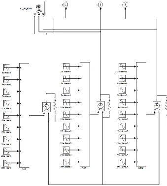
3.2.2 Fortran Software: model for harmonic analysis ... 48
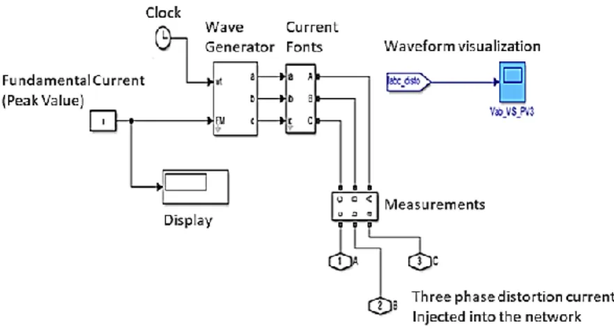
3.2.3 Simulink model for time varying non-linear load ... 50
3.3 Electrical System Dependability [2] ... 53
Chapter IV: Characterization of A Military Aircraft Carrier ... 56
4.1 System description ... 56
4.2 On-board electrical loads characterization ... 58
4.2.1 SWBS groups ... 58
4.2.2 Operating role ... 59
3
Chapter V: Cavour Aircraft Carrier– Measurement campaign [97] ... 61
5.1 Measurement campaign organization ... 61
5.2 Measurement campaign results ... 62
5.2.1 Time domain ... 63
5.2.2 Frequency domain ... 70
5.3 Software and model validation ... 75
5.3.1 Load Flow ... 75
5.3.2 Network impedance analysis – Z(f) ... 75
5.3.3 Total Harmonic Distortion evaluation ... 77
5.3.4 Simulink model for time varying non-linear load ... 79
Chapter VI: A New layout for an Integrated Power System Naval Unit-All Electric/Hybrid ... 80
6.1 Aims of the chapter [99]... 80
6.2 MV All electric ship ... 81
6.3 All electric MVAC - alternating current MV system ... 86
6.3.1 Normal operation (full propulsion power) ... 87
6.3.2 Emerging operation (half propulsion power) ... 88
6.4 All electric MVAC "hybrid" - MV system with alternating current with "islands" / electrical areas in direct current, in MV and/or Low Voltage (BT). ... 89
6.4.1 Normal operation (full propulsion power) ... 90
6.4.2 Emerging operation (half propulsion power) ... 91
6.4.3 DC island ... 91
6.5 Definition and characterization of a "hybrid" propulsion naval unit... 93
6.5.1 Network architecture ... 97
6.5.2 50 Hz network - load conditions ... 98
6.5.3 60 Hz network -load conditions ... 102
Chapter VII: Network Equivalents in Frequency Domain ... 105
7.1. Electrical network case study ... 105
7.3 Network impedance... 111
7.3.1 Network impedance evaluation for each equivalent network model ... 111
7.3.2 – The Network Equivalent Accuracy ... 114
7.3.2.1 Comparison among network equivalents ... 114
7.3.2.2 - Influence of cables length on network impedance calculation ... 117
Chapter VIII: Harmonic Analysis ... 118
8.1 Network impedance... 118
8.2 layout “Hybrid Electric/Diesel/Gas Turbines propulsion MVAC – alternating current MV system” ... 118
8.2.1 - 50 Hz network ... 118
8.2.2 –60 Hz network ... 125
8.3 All electric MVAC/MVAC "hybrid" ... 130
8.3.1 Total Harmonic Distortion evaluation “all electric” ... 137
4
9.1 Reliability of the electrical system for "all electric" layouts ... 139
9.2 System Reconfigurability ... 141
9.3 Impact of faults on the electrical system ... 141
Chapter X: Three-Phase Short Circuit Analysis For MVAC 50-60 Hz Layout ... 148
10.1 Assumptions ... 148
10.2 Simulation Results ... 153
Chapter XI: Conclusion ... 170
Acknowledgments ... 172
References ... 173
ANNEX A - Measuring Instrument ... 179
5
Acronyms
AES All Electric Ship
A Availability
AC Alternate Current
AIM Asynchronous Machine
AP Power Absorbed
CODAG Combined Diesel And Gas
CODOG Combined Diesel Or Gas
CSI Current Source Inverter
CV 550 Cavour Aircraft Carrier
DC Direct Current
DDGG Diesel Generator
DF Distribution Functions
DOL Direct On Line
e.m.f. Electro Motive Force
EMPAR European Multifunction Phased Array Radar
EPAC Electrical Fire Pump
ESS Energy Storage System
ETO Emitter Turn Off
fco Coefficient Of Contemporaneity
FECs Front End Converters
Gas Gate Turn Off Thyristor
GTO Gate Turn Off Thyristors
HP High Pass Filter
HVAC Heating Ventilation And Air Conditioning Systems
Icm A Nominal Short-Circuit Closing Capacity
Ics Nominal Short-Circuit Breaking Capacity
Icu Extreme Short-Circuit Breaking Capacity
If Field Circuit Current
IGBT Insulated Gate Bipolar Transistor
IGCT Integrated Gate Commutated Thyristors
IGCT Hard Driven GTO
IHD Individual Harmonic Distortion
IM Induction Motor
IPS Integrated Electrical System
JSF Joint Strike Fighter
LV Low Voltage
m.m.f. Magnetomotive Force
MCR Maximum Continuous Rating
MPDCC Multi-Port DC/DC Converter
MTBF Mean Time Between Failures (h)
MTTR Mean Time To Repair (h)
MV Medium Voltage
MVAC Medium Voltage – Alternate Current
MVDC Medium Voltage – Direct Current
NaSG Naval Smart Grid
NP Nominal Power
PDs Propulsion Drives
PF Power Factor
PQ Power Quality
Psc Short Circuit Power
PTO Power Take Off
PWM Pulse-Width Modulation
Q, Unavailability
QM Quality Factor
Rdt Repair Downtime
RMS Root Mean Square
RPM Revolution Per Minute
RV Random Variable
SCR Silicon Controlled Rectifier Or Thyristor
6
SM Simulink Model
SSPC Solid-State Power Controller
ST Single Tuned Filters
STANAG In NATO A STANdardization AGreement
STOVL Short Take Off & Vertical Landing
SWBS Ship Work Breakdown Systems
TAG Gas Turbine
Tf Total Failures
THD Total Harmonic Distortion
THDI Current Total Harmonic Distortion
THDV Voltage Total Harmonic Distortion
Tp Total Period
Vd Armature Circuit Supplying Voltage
VSI Voltage Source Inverter
Z(f) Network Impedance
ZEDSs Zonal Electrical Distribution Systems
λ Failure Rate (f/h)
ϕ(If) Excitation Flux
7
Introduction
Nowadays electric propulsion has become a valid alternative to mechanical propulsion for large ships that require high speed.
The electric propulsion advantages are well known and widely documented in the literature: higher dynamic performance of the electric propulsion motors; internal combustion engines separation from shafts; increased flexibility in space/zones subdivision; increased efficiency through the modulation of number of running generators; noise and vibration reduction; increasing in automation, with a consequent crew reduction.
The use of electric propulsion along with the progressive increase, in number and power, in electrical loads used for ship services, led to the development of the All Electric Ship (AES) concept. Over the last years, the All Electric Ships (AESs) concept has begun to be adopted by the most important Navies, principally by the U.S. Navy, giving a boost to the technological research.
An AES is a ship where all onboard electrical loads (including propulsion) are powered by a single electrical system, called Integrated Electrical System (IPS). The IPS requires careful design and management in order to ensure both high Power Quality standard and the continuity of the service. With the technological progress, the shipboard electrical systems have changed considerably, rising from few MW of installed power to values of the order of hundred MW, both in cruises and military ships.
Especially in military vessels, considering the number of special devices that are present on board (weapon systems, communication equipment, radar, sonar, and missile guidance systems), a performing and reliable electrical systems is required. Moreover, it is necessary to notice that some of the new electrical pulsed loads specific to military applications (e.g. radar, electromagnetic launchers, etc.) together with electric drives for propulsion engines can cause strong disturbances to the system, thus causing the malfunction of other electric utilities that may endanger the continuity of the service. The penetration of power electronics converters is the main issue for the contribution of harmonic distortion in AC grids, which must be limited not to increase system power losses, and to allow the correct operation of system and user devices. Standards dictate the maximum admissible values of the total voltage harmonic distortion and of the individual harmonics amplitudes, as a function of the rated system voltage.
The relatively limited short-circuit power available on board also exposes the IPS to significant voltage sags and flickers caused by switching and/or intermittent loads. In this scenario, DC electrical distribution systems can be very attractive, thanks to their intrinsic immunity to harmonic problems. If DC micro-grids are interfaced to AC networks by means of Front End Converters (FECs), both AC/DC grid decoupling and considerable AC-side harmonic distortion reduction can be achieved. In addition, they simplify the power supply of converter-fed loads and the interfacing of storage systems. The latter can perform several tasks, including ensuring power supply in case of AC grid loss, peak-shaving and levelling pulsating loads further improving both the quality and the continuity of supply to DC islands loads.
In the light of the above, it is evident that the electric power system is of primary importance for a modern ship. Moreover, if high-performance is required, careful analysis of the disturbances in the power system is mandatory. In fact, in order to achieve a reliable and performing power system, together with a high-Power Quality, it is necessary to assess this situation and propose guidelines to be observed for the solution of various problems.
The definition and evaluation of possible IPS architectures should take into account AC/DC protection devices in order to carry out an integrated analysis of the system. Different MVAC/MVDC electrical distribution layouts coupling with all-electric or hybrid propulsion (electric/diesel/gas turbine) needs to be accurately investigated to show its advantages in terms of reliability, safety and quality of power.
8 The thesis focusses on the Naval Smart Grid (NaSG) research project completed in partnership with the University of Trieste and the Polytechnic University of Milan. The aim of the research is to produce useful results for the design of a new ship, equipped with the following innovative features: modular power system; subsystem flexible integration; efficiency improvement; security improvement; new weapon systems; survivability improvement and high Power Quality standard. The main focus was the study of methodologies/solutions able to improve and define the onboard Power Quality (PQ). The research project reports Power Quality analysis about aspects of continuity of service, harmonic disturbances, pulsed power loads impact on the system, electromechanical transient evaluation and use of power and energy storage systems.
An exhaustive investigation was carried out on system architectures in frequency domain to identify resonances and non-linear loads to detect disturbance frequencies.
Moreover, the guidelines for the correct coordination of all the elements of the power system design affecting system performance (protections, converters, control systems, energy storage systems, etc.) are reported.
A brief abstract for each Chapter is reported.
Chapter 1 and 2 - Overview of Electrical Naval Systems and Integrated Power System in Military Ships
The chapter reports the complete state of the art on naval electrical system and a brief description of naval classification, showing technological improvements and historical evolution. Details about electric propulsion, electrical generation on board, energy distribution and network layout are carried out. A complete description of the main IPS military ships with their own architecture and features is reported.
Chapter 3 - Methodologies for Harmonic Disturbances Analysis and Power Quality (Service Continuity)
In the field of Power quality (harmonic content, asymmetries, voltage sags, power factor), methodologies applied for the analysis/detection of harmonic disturbances are reported with an overview of electrical systems dependability in order to evaluate the service continuity of the system. Harmonic distortion could affect equipment on shipboard causing its outages, consequently, in an island system, power distribution network should ensure high re-configurability after faults, damage or untimely switch off. However, the increased interest in system’s safety and resilience generates, in turn, an increase in design burden necessary to analyze the consequences of faults and demonstrate the system’s compliance with the relevant regulations.
The chapter presents the models and calculation code used for simulation activities. A Simulink model for time domain analysis and for time varying non-linear load, as well as a Fortran model for harmonic domain are described.
Chapter 4 and 5 - Characterization of a military aircraft carrier and Aircraft Cavour – Measurement campaign
A measurement campaign onboard the ship Cavour was carried out with the aim to characterize the relevant electric loads on board military vessel and to validate the models of the system’s components to be used.
The analysis of data collected, allows to model the behavior of loads in terms of time and frequency domains, thus permitting their use for the required studies. Some specific electrical loads, such as new electrically pulsed loads specific for military applications (e.g. radar, electromagnetic launchers, etc.) with high distorted current absorption were identified. Their characterization was carried out in order to define their contribution to harmonic disturbances and their impact on the network. A model validation based on a measurement campaign is carried out.
9 Chapter 6 - A New layout for an Integrated Power System Naval Unit-All Electric/Hybrid
Different IPS architectures are defined: a full MVAC (Medium Voltage Alternate Current) power system, a hybrid MVAC plus MVDC/LVDC islands (Medium/Low Voltage Direct Current) and a MVAC 50-60 Hz, with a hybrid (electric/diesel/gas turbine) propulsion. In the architecture of the latter, the power of the installed engines is much lower than the first two cases.
Chapter 7 - Network Equivalents in Harmonic Domain
The needs to easily represent a complex network with high accuracy, lead to the development of a methodology based on aggregation of loads, creating a simplified network to carry out harmonic analysis.
Different equivalent network models have been proposed that show their accuracy, through network impedances, and compare them with the overall representation of the network. The influence of cables was also studied. The best radial equivalent network was identified.
Chapter 8 - Harmonic Analysis
In order to propose appropriate solutions designed to improve power quality, the study of system impedance and power systems in frequency domain were studied. This analysis, carried out on the basis of the schematics and data load obtained in cooperation with the IT Navy, revealed some criticalities in the frequency range for both the systems architectures.
As to full MVAC (Medium Voltage Alternate Current) power system and hybrid MVAC plus MVDC/LVDC islands, the aim was to evaluate whether or not the inclusion of capacitors (on shore, for power factor correction in shore connections) or filters (onboard, to reduce harmonic disturbances produced by propulsion systems) cause special issues, because of the high power of installed propulsion engines. Moreover, the advantages of DC island on electrical distribution in order to ensure high reliability and quality of service, in addition to the need to increase the efficiency of the ships’ power systems are highlighted.
For the MVAC 50-60 Hz layout, the goal is to show how the use of hybrid (electric/diesel/gas turbine) propulsion where the power of engines is significantly reduced as compared to previous cases could solve some issues relating to power quality aspects.
Chapter 9 - Reliability Analysis
Preliminary studies about dependability, re-configurability and some top-events relevant for the vessel, were evaluated for all electric MVAC/MVAC "hybrid" models. The analysis of electrical disconnection of load areas due to a fault or an untimely tripping of the switches caused by harmonic disturbances was carried out.
Chapter 10 - Three-Phase Short Circuit Analysis For MVAC 50-60 Hz Layout
Preliminary evaluations were performed by analyzing the system within the perspective of given faults to perform system analysis in both permanent and short-circuit conditions. To highlight possible protection issues, the steady state condition and the three-phase short-circuit faults were studied and simulated under different load conditions for the MVAC architecture plus rotary converters, with hybrid (electric/diesel/gas turbine) propulsion.
10
Chapter I: Overview of Electrical Maritime Systems
1.1 Electrical Propulsion System in Ships
The concept of electric propulsion was introduced in the naval field since the nineteenth century. The vessels used in Europe were driven by electric motors fed by direct current [1] both in the civil and military field. The electric propulsion developed thanks to this technology, was favoured by the difficulty to create gear reducer systems, necessary to couple the propeller shaft1 with the high- power
steam turbines axis, as they operate at different rotational speeds.
Through the use of specific electric machines2 it is possible to diversify the speed of both engines
and propellers. Once the difficulties related to the development of speed reducers were solved, the mechanical propulsion became the main system adopted in naval applications.
The technological development of electric propulsion was to become a topic of interest after the Second World War, thanks to the evolution of power electronics.
Nowadays, electric propulsion systems are widespread for passenger ships and other types of vessels (ferry boats, icebreakers, tugboats, etc.).
Based on the definition, electric propulsion occurs when the motor that drives the propellers is an electric engine; instead mechanical propulsion is when the main engine is typically a diesel or gas turbine.
The use of a diesel engine to generate the motor torque necessary to provide propulsion, implies a major economic disadvantage: in order to vary the power supplied to the propeller (also called brake power) it is necessary to operate the engine under variable rotation levels, based on sea conditions, ship speed, and – sometimes – on the adjustment of propeller’s pitch, when the vessel is equipped with controllable pitch propellers (CPP), rather than fixed pitch propellers (FPP). Adjusting the power by means of rotation speed variation does not allow to maintain the diesel engine at its maximum efficiency, i.e. at a constant RPM. This causes an increase in the specific consumption of fuel that, also because of engines size and hours of navigation, may result in higher operating costs. When performing power regulation, varying the rotation speed, it is not possible to maintain the diesel engine at the point of maximum efficiency (RPM constant). For this reason, an increase in operating costs is due to higher fuel consumption. Furthermore, it is still necessary to have additional prime movers to generate electricity to supply ship services.
This system is defined as "not integrated", in so far there is a separation between the prime movers used for propulsion systems and those used for electricity generation to supply ship loads. There is no possibility for the two systems to interact.
The evolution of the architecture was developed to share the generators both for electric propulsion systems and for the power supply of ship loads. This system is defined "Integrated", and allows to install fewer prime movers on board and, consequently, fewer auxiliary systems necessary for their operation; it became a flexible system, with a reduction in specific fuel consumption, operating costs, and an increase in plant reliability.
The invasive adoption of electric powered equipment, both for electric propulsion and electric devices, led to the origin of the so-called All Electric Ships (AESs). Such ships are equipped with a power system supplying all shipboard loads, included propulsion, by means of a common set of generators. Because of this, and thanks to its possibility to reroute the power wherever is needed at a specific time, the power system was called Integrated Power System (IPS).
1 In the mechanical propulsion, it is necessary to develop a shaft that connects the axis of the main motor to the
axis line on which the propeller is keyed. This shaft across the entire distance between the engine room and the installation point of the propeller, sometimes reaches considerable lengths.
2 For example, a coaxial group with an internal combustion engine, a dynamo, a direct current motor, allows
to vary the propeller speed keeping the main mover at constant RPM, therefore working at the point of maximum efficiency
11 An Integrated Power System can be considered equivalent to a land power grid, where generation, distribution, and utilization of the electric power coexists in a limited space (an example is shown in Figure 1). In an All Electric Ship, the Integrated Power System is the core system, being every load electrically powered. Losing power generation (blackout) means losing the ship control, which can lead to harmful consequences for people, things, and the environment.
Nowadays the AES concept is widely applied on large ships: only ships with special requirements, such as high speed or peculiar fuel, still use mechanical propulsion.
Other applications of AES concepts are: ferries, oceanographic ships, gas carriers, cable/pipe laying vessels, oil & gas dedicated vessels and platforms, icebreakers, and mega-yachts.
Different reference should be made for the military area, where mechanical propulsion solutions have so far been the only option considered. This is because of both high speed and reliability requirements of naval vessels, which led designers to focus on well-proven technologies. However, in recent times greater attention was paid to electric propulsion also in the military area. This was clearly demonstrated by the growing number of research projects on this type of propulsion in all the most technologically advanced navies with the construction of new all-electric military ships [2] [3] [4].
12
1.2 Electric Propulsion – Historical overview
Figure 2 reports a timeline listing the main milestones in marine vessels power systems [6].
A brief description of famous and historical ships that used electric propulsion in the past is reported.
Figure 2 - Historical highlights of the evolution of marine vessels’ electrical power systems: timeline.
Amerigo Vespucci - Figure 3
The ship has been in service since 1931, and it is currently employed by the Italian Navy as a school ship of the Naval Academy in Livorno. Built as a sailing ship, over the years it received a lot of upgrades/refitting’s and today it is equipped with 2 diesel/dynamo Fiat B-306-ESS groups, and a Marelli electric engine which drives 1 axis with a fixed blade propeller. The total power installed is 1471 kW [7].
13
Normandie - Figure 4
It was built in France as an ocean liner that connected "Le Havre" to "New York". In service since 1935, it reached a speed of over 30 knots. It was equipped with:
29 boilers with naphtha combustion;
4 cylindrical auxiliary boilers with smoking pipes, which operated 4 steam turbines connected to alternators.
The generators, which powered 4 synchronous electric motors (each by 30 MW power) coupled to 4 propellers, produced a variable electric system frequency (0 ÷ 81 Hz) for a 120 MW total power. The advantages were:
the possibility of rotating the propellers at different speeds from those of steam turbines without mechanical speed reducers;
steam turbines were installed in the lower areas of the hull, to the advantage of stability, since the generators did not need to be mechanically connected to the electric propulsion engines; propeller reversal rotation was obtained without the use of an auxiliary turbine [8].
Figure 4 - Normandie
Queen Elizabeth 2 – Figure 5
Property of Cunard Line from 1969 to 2008, it was used both as a transatlantic and cruise ship (apart from a short period during the Falklands War, when it was used for troops transportation). Originally equipped with three boilers supplying 2 steam turbines, as a consequence of serious reliability issues and operating costs due to fuel consumption, it was upgraded with the replacement of the steam system with a Diesel-Electric system. The new architecture had nine motor-generator groups (10.5 MW) at 10 kV rated voltage. The system powered both the ship services and the two 60Hz synchronous electric motors (44 MW at 144 RPM), which operated two variable pitch propellers. The two propulsion engines were powered by a synchronous inverter, at low speeds up to 72 RPM, and directly from the 60 Hz network for speeds above 18 knots, varying propellers pitch [9].
14
1.3 Naval Classification
Nowadays, many ships characterized by different power, dimensions and utilizations, sail the commercial routes in maritime world transport.
Ships are classified based on their field of use and the type of on-board energy generation system. A general overview of the various types of ships in the world is reported in [1].
1.3.1 Field of use
Ships for passenger transport
It includes cruise ships, transatlantic ships, ferryboats and yachts. This type of boat is characterized by high standards in terms of comfort and hull vibrations, as well as high standards of safety and system reliability.
Private companies rather than public ones own these ships; a common prerogative is to reduce operation costs and increase ship manoeuvrability (a cruise ship is currently able to rotate with millimetric precision).
Figure 6 - From left to right Cruise ship (Costa Diadema), Ocean Liner (Queen Mary 2), Ferryboat (Normandie Express), and Yacht (Fincantieri Mars)
Cargo ships
Cargo ships are both Tankers (oil tankers, chemical tankers, gas tankers or methane tankers), used for fluid or gas carriage and ships the carriage of solid materials (container or bulk carriers). In the first category, common safety standards for the carriage of flammable fluids and gases, or for highly dangerous chemicals are required. The second has a high load capacity with a heavy ship weight. Sophisticated loading/unloading and materials storage systems are required.
Figure 7- From left to right Oil tanker, Gas tanker (Golar Frost), Container ship (Maersk Triple E), and Bulk Carrier (Beluga Nomination)
Ships for the Oil & Gas application
This category includes units for oil and natural gas drilling, extraction and treatment, ships for oil platforms building, transportation and assembly, as well as production support vessels. All the above-mentioned ships meet the same requirements: oil and gas are often located in extreme environments, especially for offshore platforms, and the structures are therefore subject to high mechanical stress within adverse climatic conditions. For these reasons and for the need to operate them in specific locations, all these units are equipped with a "Dynamic Positioning": using GPS technology and radar systems for geolocation.
15
Figure 8 - From left to right: oil platform (Troll A), Lifting platform (Saipem 7000), Pipelayer (MV Solitaire), and Floating production platform (Maersk Peregrino)
Warships
Warships require maximum performance in terms of speed and autonomy, as well as resistance to damage. Different innovative technologies converge on on-board systems and high reliability standards are required. Warships include a very large number of categories, depending on the mission they perform.
Figure 9 - From left to the right FREMM (F590 Carlo Bergamini), USS Ohio (SSGN 726), USS Nimitz (CVN-68), USS Independence (LCS-2)
Other ships
Other types of ships are listed below:
icebreakers: ships equipped to sail through frozen areas and open the route to other ships that, otherwise, would be unable to reach some areas of the world. Some of these ships also carry out scientific research activities;
dredges: ships equipped to underwater excavation of harbours seabed, canals, rivers or lakes. They remove any deposited sediment, dangerous for navigation;
fishing Ships: cover almost all world seas, engaged in fishing activities preserving also a great variety of fish species;
semi-submersible ships: units designed for sea transportation of big structures that cannot be transported by land or sea. Moreover, they are suitable for the sea recovery of ships and/or platforms unable to get back to ports because of damages.
Figure 10 - From left to right: Icebreakers (CCGS Amundsen), Dredge (TSHD Cristobal Colon), Fishing ship (Northern eagle), and Semi-submersible ship (Dockwise Vanguard)
16 1.3.2 On-Board Power
Ships are commonly defined based on the typology of power plant systems installed on board. In particular, the three typical architectures are the following: not integrated, integrated and hybrid.
Not integrated system
In a non-integrated power system, some engines are dedicated for ship propulsion, while others are destined to feed the engines’ auxiliary systems and ship services. These two systems are completely separate and unable to mutually interact. Moreover, there are mechanical propulsion issues, such as the variable RPM engine (maximum efficiency is not reachable), critical speed of the propulsion system3, and complex manoeuvres for crash stops4.
Integrated systems
On-board power systems share the electric generators to feed both ship services and electric motors’ auxiliary systems as well as the electric propulsion system.
Hybrid systems
All electric systems require the installation of high power and generally very bulky machines. A hybridization of generation systems is carried out to obtain more space available on board. In the military field these types of systems are often used, even for the high speeds required. Possible configurations are reported:
CODAG (COmbined Diesel And Gas) and CODOG (COmbined Diesel Or Gas): these systems involve the use of diesel engines and gas turbines for propulsion, and they differ for the simultaneous use (CODAG) or the exclusive use (CODOG) of two generation systems. In both cases, diesel engines are used in lower speed ranges, while gas turbines are used to reach maximum speeds.
Figure 11 - a) CODAG; b) CODOG
1.4 Electrical Generation On Board
The choice of the system for electrical generation is the main important step of electrical naval design. The choice of generation units selected based on their type, number and size takes into account a great number of aspects and technical-economic requirements.
A difference with a common electrical industrial grid is the surrounding environment of use.
3 Rotational speeds of the axis-motor in which the vibrations are greater, sometimes even dangerous, as
compared to other speed ranges, due to resonance phenomena of the rotating systems.
4 Operations to perform an emergency stop. A ship sailing at a constant speed, has greater inertia, due to its
17 On board humidity levels and ambient temperature (45° and 55° C, respectively for common zones and electrical panels/machines rooms) may reach high values with possible difficulties for heat dissipation.
Moreover, many standards and regulations affect design decisions related to safety and security, reliability, vulnerability and systems redundancy. First of all, the International Convention for the Safety of Life at Seas imposes fundamental requirements (IMO SOLAS 19745 [10]). The first version
was written in 1914 in response to the Titanic disaster. The most important concept, upon which the standard is based, is that the ships, engaged on international voyages, must return back to port in whatever condition (damage and malfunctioning) to ensure the safety of the people and equipment on board. The standard reports that the normal operational and habitable condition is a condition under which the ship as a whole, the machinery, services, means and aids ensuring propulsion, ability to steer, safe navigation, fire and flooding safety, internal and external communications and signals, means of escape, and emergency boat winches, as well as the designed comfortable conditions of habitability are in working order and functioning normally. Emergency condition is a condition under which any services needed for normal operational and habitable conditions are not in working order due to failure of the main source of electrical power.
Electrical installations shall be such that: all electrical auxiliary services necessary for maintaining the ship in normal operational and habitable conditions will be ensured without recourse to the emergency source of electrical power, electrical services essential for safety will be ensured under various emergency conditions; and the safety of passengers, crew and ship from electrical hazards will be ensured.
Starting from these simple rules, a common design is the installation of two electric power generation plants located in two different sections of the ship in separate compartments.
As a result of a fire, a flooding or malfunction of one electric generation plant, it is however possible to get back to port with a system performance degradation due to the limited power available from the other generator. The same approach could be applied to propulsion systems. It is possible to increase the ship’s reliability by installing propellers with two axis lines and two propulsions motors with two drivers installed in different and separate zones of the ship [11].
In addition, the generating sets shall be such as to ensure that with any one generator or its primary source of power out of operation, the remaining generating sets shall be capable of providing the electrical services necessary to start the main propulsion plant from a dead ship condition. The emergency source of electrical power may be used for the purpose of starting from a dead ship condition if its capability either alone or combined with that of any other source of electrical power is sufficient to provide at the same time those services required to be supplied by regulations. A total system failure need two failures events at the same time and its probability is the product of the singular failure probability. Therefore, by increasing redundancy of the equipment, the overall reliability will improve.
Inside the power plants, the power is subdivided into two or more groups (DDGG – Diesel Generator) in order to ensure the nominal power also in case of unavailability of one generator (N-1) and manage the navigation operational profile of the electrical system operating the Diesel generator at function point with maximum efficiency (75% for Diesel relating to MCR6) as shown in Figure 12.
In power plants design a 10 % more of power is consider to taken into account the increase of electrical loads or new equipment that will be install during the years (Life cycle is 20-30 years).
5 The present regulations, unless expressly provided otherwise, do not apply to: ships of war and troopships,
cargo ships of less than 500 gross tonnage, ships not propelled by mechanical means, wooden ships of primitive build, pleasure yachts not engaged in tradem, Fishing vessels.
18
Figure 12 - Specific Fuel Consumption Related To The Percentage Power
Over the years, as regards the electric machines used for electrical generation, the evolution from a synchronous machine with main coaxial exciter (DC current generator) was a synchronous machine with static exciter or a permanent magnets machine with 50 or 60 Hz frequency. The polar pairs ranging between 1 and 8 respectively for high-speed turbo-generator (3000/36007 RPM) and
generator coupled with a medium speed Diesel engine (375-4506 RPM).
In naval power network, the short circuit power (Psc) is low8, especially in operation profile with low
power consumption, with one or two operating generation groups.
The break of one generation unit during navigation is more dangerous than in land systems, where the power deficit could be filled by the rotating reserve thanks to the grid interconnection.
Inside the ship the rotating reserve assumes lower values that could pose a critical situation.
Another aspect influencing the stability of the network is that electrical loads with a nominal power comparable with the size of power generators are installed on board.
To manage the insertion of high power loads it is necessary to adopt a soft starter strategy or sequential insertion and frequency and voltage regulators having stability dynamic performance. The frequency and voltage regulator combined with the automation system coordinates generators insertion and detachment, thus reconfiguring the network thanks to generators operation ad faults. A gas turbine could be coupled with diesel generators reaching 50 MW nominal power.
Gas turbines are lighter and with greater power density; it is possible to install them in areas above the vessel’s gravity center without any loss of stability.
For example a Rolls Royce MT7 gas turbine (5 MW) weighs 440 kg and occupies 1 m3 volume,
while a Wartsila 16V26 Diesel Generator of the same electrical power weighs 70 Tons and occupies 96 m3 volume.
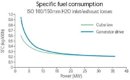
The use of gas turbines is limited to specific applications because the high specific consumption of fuel increases if the turbines operate under 50 % of their nominal power, as show in Figure 13.
7 Referred to 60 Hz application.
8 In naval network it is not possible to adopt the short circuit equivalent model adopted for generator with
19
Figure 13- Specific Fuel Consumption Related to the Axis Power Generated
Moreover, an axis gear speed reducer is required to make the turbines speed compatible with the propellers speed or the electric generator. It introduces extra losses that constitute a weakness of the system.
The gas turbines are used to reach high speed (frigates, cruisers, aircraft carrier, etc.).
To improve the overall efficiency of gas turbines it is possible to couple a steam system with thermal energy recover to produce electrical energy and hot water for on board auxiliary system.
1.5 Energy distribution
Energy distribution starts from power stations, where power generation is subdivided and installed in the main electrical panels. The groups9 are divided into at least two bars (reliability standard), with
the possibility of parallel operation by closing a special bar-joint.
The on board power plants supply the entire vessel’s loads dislocated into different areas of the ship. For example ambient temperatures in engine rooms reach high value and these rooms are subject to fire and explosion risks; the equipment installed outside the ship is subject to bad weather condition, electrical loads for medical use, indeed, need high safety standard, etc.
Network layouts, voltage levels and neutral operation, generally adopted on board are illustrated in the following chapters [12] [13].
1.5.1 Network layout
The energy distribution system could be defined as radial, double radial, or meshed network.
radial network (Figure 14a): it is the simplest layout, the main electrical panel has a single section from which all sub-electrical panels are supplied. This layout is the least reliable, because any failure of the main bus-bars can lead to the collapse of the entire electrical system.
compound Radial network (Figure 14b): it is an evolution of radial network where the main bus-bar is divided into two section with Sub-electrical panel distribution. They divide the power supply to various areas of the ship. Essential load (high continuity requirement) could provide a cross connection supply coming from a separate section, powered by an independent power source. An evolution, adopted by Italian Navy, is the double radial network where each ship zone can be fed from one power station or another.
20 meshed network (Figure 14c): this system has high reliability level, it is possible to reconfigure the system during a fault, by isolating the faulty electrical section. In this type of network, it is possible to adopt directional protections to increase fault selectivity.
Figure 14- a) Radial b) Compound Radial c) Meshed
1.5.2 Voltage levels
Voltage levels are dictated by power generators and loads installed on board, and classes and insulation distances of the equipment, as well as the type and number of power wires must be sized based on them. Depending on network layout and installed power, more voltage levels are suitable, differentiating into primary, secondary and terminal distribution. In primary distribution voltage levels depend on the total power installed. Medium voltage generation and distribution systems for large ships normally provide 11 kV voltage level for 20 MW generation power plant and engines with power greater than 400 kW, while 6.6 kV distribution voltage is adopted from 10MW to 20MW generation power plants and engines with maximum powers around 300 kW. Other standardized voltage levels (4.16 kV, 3.3 kV, 1 kV) are used according to the geographical area of ship construction, in compliance with the different standards in force. In small boats such as yachts ranging from a few megawatts up to about 12 MW of installed power, voltage generation and distribution level normally occurs with 400 V and 690 V at 50 Hz, 115 V and 440 V at 60 Hz [14],
[15]. Figure 15 shows the range of voltage levels relating to the power installed.
21 1.5.3 Neutral operation
In three-phase four-wire networks, the neutral conductor is connected to the neutral point of the transformer or the generator that supplies the network.
In normal operation (symmetrical sinusoidal regime), the neutral conductor is located at ground potential and therefore voltage and current do not change. In perturbed conditions, during short-circuits dissymmetric on the ground, voltage and currents on the ground depend on neutral connection.
The three-phase transmission and distribution networks are designed and operated in such a way that they are as much symmetrical as possible. However, networks can work in a dissymmetric regime when phase to ground or phase to phase short circuits occurs.
The value of the fault current must be evaluated as it depends on the coordination of protections and the damaging effects at the point of failure, as well as the pitch and contact voltages that are generated to the ground. The value of temporary overvoltage must be evaluated for the dimensioning of the equipment insulation, components and users, as well as for the assessment of the risks of electrocution by direct contact.
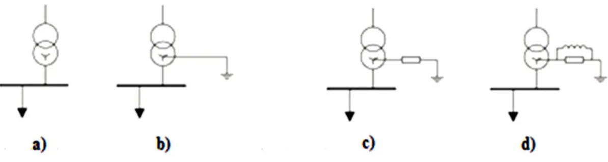
We can devise two diametrically opposed ways of operating the network neutral: Neutral connected directly to the ground;
Neutral isolated from the ground.
A third mode of neutral operation the ground connection through impedance is also implemented by several network operators, especially in MV networks.
This solution permits to limit the current values and, at the same time, to reduce over-voltage phases not affected by failure. The ground connection impedances of the neutral can be of different types and values; among them, the solutions generally adopted are: resistance, inductive reactance, and inductive reactance in parallel with resistance.
Neutral Grounding via resistor allows to limit single-phase fault currents to ground and permits line protection through simple homo-polar amperometric relays. The use of inductance instead reduces the earth fault current at negligible values. Neutral grounding through inductance in parallel with a resistor compensate the capacitive earth fault current and keeps the current at low values that are detectable by traditional relays. Figure 16 shows, the various neutral layout admissible [16].
Figure 16 - a) Neutral Isolated b) Neutral Grounded Directly c) Neutral Grounded by Resistance d) Neutral Grounded Via Impedance
Common neutral operation architecture in maritime electrical systems are discussed. In particular, the list below reports the common neutral operation solution for power generators, and for primary and secondary distribution of naval systems [13].
power generators and primary distribution: it is better to operate generators with neutral isolated from the ground, or connected by impedance. In this case the earth fault currents are reduced to low values (few amps) generally tolerated by the machine windings.
22
The solution with grounded neutral by high value impedance is a compromise between isolated neutral systems (high over-voltages and low ground fault currents) and systems with neutral directly connected to the ground (high ground fault currents). In both cases, a first fault with relative insulation loss allows to keep the system operating without tripping the protections. Obviously, is necessary to repair the fault to avoid that the first fault evolves into a double ground fault, that is more dangerous in an isolated system. The insulation level is continuously monitored;
secondary distribution: in the past, when the on-board systems were not very large and with
low power generation, the secondary distribution system was a single-phase network with two/three insulated conductors with a medium point of the transformer connected to the ground. Today, due to the increase in power generation, the three-phase system with distributed neutral is, in most cases, not connected to the ground. Therefore, it is possible to arrange the phase-to-phase and phase to ground voltage. The secondary distribution network is generally distributed radially with the possibility of double switchboard power supply via two different lines, implementing the reserve connection.
Table 1 summarizes the distribution systems used on board, differentiated by voltage level and by sector of use.
Table 1 - Neutral Operation for Different Distribution Systems
Medium Voltage Low voltage
Power Generators Ground with impedance isolated Primary distribution Ground with impedance isolated Secondary distribution/essential
load isolated
Secondary distribution/non essential load
To the ground with differential protection device Electric propulsion supply Isolated or to the ground with high
value impedance
Isolated or to the ground with high value impedance
1.6 Electric propulsion system
A brief description on common electric propulsion engines is reported; it highlights different characteristic and performance based on their field of use [13].
DC motor: it was the first type of electric machine used for ship propulsion. Nowadays DC engines have been replaced by synchronous or asynchronous alternating current engines because of better performances. DC motors were limited to low power applications, due to the problems related to high currents switching on the machine’s collector and the presence of brushes.
Asynchronous AC motor: it is the most widespread and used engine in the world thanks to its low manufacturing costs, robustness and reliability, as a result of the limited number of constituent parts and the absence of sliding contact. Rotation speed depends on frequency of voltage supply and it is characterized by lower starting torques as compared to nominal ones.
As for weight and dimensions, they are similar to synchronous AC motors also in size. For example,
a 20 MW asynchronous machine (AIM) occupies about 18 m3 and weighs about 70 tons, while a
synchronous equivalent with permanent magnets (Jeumont axial flow) occupies about 17 m3 and
weighs about 65 tons [17].
The definition of poles number and stator winging phases, as well as a targeted structures design, could reduce the noise produced. This is an important aspect for passenger transport vessels but even more in military vessels, whose safety also depends on their level of detection, so it is essential for them to reduce acoustic emissions.
23
Synchronous AC motor: it is widely used, on cruise and military ships. These machines are versatile and operate indifferently either as electric motors or as generators, without performance losses. Synchronous machines, in a CODLAG system, operate as electric motors to drive propellers, and also as generators (SG) producing electrical energy when the propulsion is entrusted to the gas turbines that are coupled to the axis lines through speed reducers.
Synchronous machines can be subdivided into two manufacturing types: with rotor winging field and permanent magnets. The first ones regulate the machine excitation both in normal and emergency operation; they have additional losses (Joule losses in the inductor windings).
Adopting a brush and ring system for feeding the rotor circuits, they are globally more cumbersome compared to permanent magnet machines. For these reasons, they are not used as engines for ship propulsion.
Exceptions are synchronous machines with rotating diode excitation, in which a transformer with wound stator and rotor, is used instead of the ring and brush system. The rotor is connected to a rectifier bridge, which feeds DC power supply to the field winding of the synchronous machine. The transformer and the synchronous machine are coaxial, and the transformer’s rotor, the diode bridge and the synchronous machine field winding are arranged on the same drive shaft.
Permanent magnet synchronous motors could beadopted in ships. The inductor’s magnetic field is
not provided by a winding, but by permanent magnets installed inside the rotor. They are extremely compact and need low maintenance, while it is possible to regulate the magnetic field produced by the rotor only with appropriate modulation techniques through electronic drives. The permanent magnet synchronous machines are classified, according to the type of magnetic structure, in axial flow, radial flow and transverse flow. The first ones are characterized by a flat rotor upon which the permanent magnets are mounted, and by a stator (flat) where stator windings are placed.
The magnetic flux spreads in axial direction, parallel to the rotation axis, making the machine extremely compact. Moreover, it is possible to exploit modular structures, through several rotor and stator stages, to increase the nominal power and maintain a high power density in extremely compact spaces. Radial flow machines are the most traditional, they have a mainly axial distribution and are the ones with higher rotation speeds performance, unlike axial flow synchronous machines that display problems due to centrifugal forces. Transverse flow machines are composed of a ring comprising the permanent magnets, which rotates between two rings constituting the stator windings and being coaxial to the rotor ring. The magnetic flux produced by these windings passes through the rotor ring through a series of stator expansions. In addition to the described categories, engines for naval propulsion exploiting the technology of high-temperature superconducting materials are being developed to obtain more compact and higher power density machines.
Figure 17 shows a comparison between a traditional synchronous motor and a synchronous motor with high temperature superconductors.
.
Figure 17 - Comparison Between A Traditional Synchronous Motor and A Synchronous Motor with High Temperature Superconductors
24
1.7 Electric propulsion’s driver
Widely used power converters for electric propulsion’s drivers are: AC/DC converters for direct current engines;
current source inverter (CSI) for AC engines, generally synchronous motors; cyclo-converters for AC motors, generally synchronous motors;
voltage source inverter (VSI), generally for asynchronous motors.
DC Converters for direct current motors
The most commonly used naval propulsion’s DC engine had an independent excitation circuit, in which the power supply of the excitation winding was separated from that of the armature winding. A converter manages mechanical parameters, such as the torque and the rotation speed.
In particular:
𝑉𝑑= 𝑘 ∙ 𝜙(𝐼𝑓) ∙ 𝑛
Where Vd is the Armature circuit supplying voltage, k is a manufacture constant, 𝜙(𝐼𝑓) is the
excitation flux generated by the field circuit current (𝐼𝑓) and n is the mechanical rotation speed.
To speed adjustment, armature voltage or magnetic flux excitation control is required, keeping one of the two variables constant and adjusting the second one. Moreover, the supplied torque is proportional to:
𝑇 = 𝑘 ∙ 𝐼𝑑∙ 𝜙(𝐼𝑓)
Where T is the axis mechanical torque produced and Id is the current of the armature circuit. Also, in
this case, by alternately adjusting one of the two variables it is possible to adjust the mechanical axis torque produced.
A main thyristor bridge is used to supply the armature circuit, while an auxiliary rectifier supplies the excitation circuit power supply. If the engine drives a fixed pitch propeller, it is possible to guarantee the maximum available torque for all the speed range, up to the nominal value, performing speed regulation by controlling the armature voltage.
The Vd is linked to the supply voltage of the AC system:
𝑉𝑑=
3√2
𝜋 ∙ 𝑉𝐿𝐿∙ 𝑐𝑜𝑠 𝛼 ≅ 𝑉𝑑0∙ 𝑐𝑜𝑠 𝛼
Where VLL is the nominal rated voltage of AC system, α is the thyristors’ triggering angle. By varying
the angle α between 0 ° and 180 ° (for stability reasons the variation range is about 15 ° ÷ 150 °) it is possible to supply the dc engine with a voltage ranging between ± Vd0.
The disadvantage is that, since the cos 𝛼 ≅ cos 𝜑 relation is valid, the drive absorbs current with a variable power factor between 0° and 180°, and proportional to speed rotation [18].
Figure 18 - A) Thyristor Bridge Drive for DC Propulsion Motor B) Grid Side Voltage And Current Absorbed By Converter C) Trend Of The Electrical Parameters According To The Rotation Speed
25
CSI current source inverter
A current source inverter, also called Synchronous inverter, is characterized by: a thyristor bridge that performs AC/DC conversion, a direct current link with smoothing inductor and a full bridge DC/AC converter that feeds the electric motor. This type of drive is often used to supply synchronous engine but, with some changes, it can also supply asynchronous engines.
The polarization of the thyristors is obtained by means of e.m.f. generated by the synchronous motor in over-excitation, absorbing capacitive reactive power.
The synchronous converter can supply only a synchronous motor. To couple it with an asynchronous motor, it is necessary to insert a capacitor bank between inverter and engine, to supply the reactive power needed and an auxiliary thyristors switching, to manage speeds lower than 60% of nominal speed due to insufficient e.m.f. when the valves are turned off.
With synchronous motor, the stator windings absorb rectangular currents from the inverter, as shown in Figure 19.a, with a high harmonic content [19].
Figure 19 - a) Stator Currents Absorbed By The Synchronous Motor From The Inverter b) Trend of The Magneto-motive Stator Force Within The Period of The Mains Supply Voltage
Figure 19a shows that within a period of the network voltage each thyristor conducts for 60 electric degree.Figure 19b shows that also the magneto-motive force related to the stator phases vary every
1/6 of the period. The trend of the stator magnetomotive force (m.m.f.) is transformed into multiple
frequency torque pulses, in so far it is linked to the stator magnetic flow by the following:
𝑇𝑒𝑚= 𝑘 ∙ 𝛷𝑒∙ 𝛷𝑎∙ 𝑠𝑖𝑛 𝛽
Where Tem is the air gab electromagnetic torque, k is a manufacture constant, Φ𝑒 and Φa are respectively the excitation and armature magnetic flux, β is the electrical angle between Φ𝑒 and Φavectors.
While the excitation magnetic field rotates at a constant speed, the one induced by the stator currents takes on a jerky pattern, from which the high frequency ripple of the driving torque arises.
To mitigate this phenomenon it is possible to adopt double stator windings, to obtain homonymous phases e.m.f. of 30 electric degree offset. The number of positions assumed by the magnetic field passes from 6 to 12, decreasing the torque ripple.
Finally, to reduce the currents harmonic distortion, it is possible to use multiple-pulse reactions, 12, 18 or 24 pulses, significantly reducing the current total harmonic distortion.
Figure 20 shows an electric drive with two synchro-converters supplying a synchronous motor with dodecaphase reaction.
26
Figure 20 - a) Synchronous Converter for Synchronous Motor b) Trend of The Electrical Parameters Relating Rotations Peed
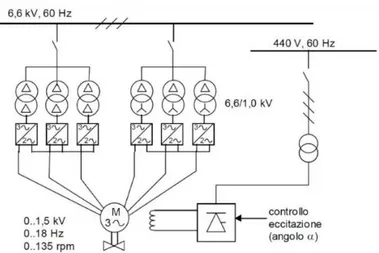
Cyclonverters
The cycloconverter is a device consisting of two full bridge thyristors connected in antiparallel. It converts an alternating voltage with constant frequency and amplitude into an alternating voltage with variable frequency and amplitude. This conversion occurs in a single stage, without continuous connection (DC link), linearly varying the α trigger angle of the thyristors. A voltage close to the sine wave is obtained.
This drive is mainly used with synchronous motors; with three single-phase cycloconverters it is
possible to supply the stator windings of the synchronous machine (Figure 21a).
Figure 21- a) Drive with Three-Phase Cycloconverter to Supply a Synchronous Motor b) Motor Supply Voltage Obtained By Selecting Defined Segments Of Network Voltages
Figure 21b shows output voltage waveform obtained by selecting a defined segment of the input waveform. The current harmonic content of the input depends on the ratio between the input/output voltage frequency which cannot decrease below 2.5 (the output frequency can be maximum 40% of the input frequency). The main advantage is the high torque value available at low speed, being therefore suitable for propeller systems of icebreakers, passenger and dynamic positioning ships. The network power factor depends on the engine’s voltage and varies with the speed ranging between 0 ÷ 0.75. It is possible to fulfil multi-pulse configurations to limit the current harmonic content
absorbed by the network, Figure 22 shows a diagram of a three-phase cycloconverter with
27
Figure 22– Cycloconverter for Synchronous Motor
VSI voltage source inverter
The most widely used voltage source inverter electronic switches with forced commutation are: IGBT (Insulated Gate Bipolar Transistor);
GTO (Gate Turn Off Thyristors);
IGCT (Integrated Gate Commutated Thyristors).
The frequency conversion is performed in three stages as reported in Figure 23: a direct current stage (DC link) is obtained from the power supply via rectifier. It is characterized by a constant voltage Vd
maintained by a LC filter designed to dampen the voltage ripple limiting the absorption of current harmonics from the network. The DC voltage is transformed into a symmetrical three-phase voltage by an inverter using voltage modulation techniques for feeding the engine windings.
The interdiction of the circuit-breakers is operated through an external control logic circuit. Thanks to this solution it is possible to use this type of converter with asynchronous motors, reaching significant powers, also at low speed.
Figure 23 - Driver with Impressed Voltage Inverter The most common modulation techniques to obtain output voltage are:
scalar control: it is the simplest control technique based on the stationary electric model of the asynchronous motor. It has a poor dynamic performance, as model parameters strongly depend on frequency, temperature, etc. Furthermore, the output voltage contains high frequency oscillations and widely varying switching losses;
28 rotor flux vector control: the method is based on the voltage vector model, flow and motor currents in a rotating coordinates system. It is possible to decouple the machine flux and the torque, and independently control the two parameters. This technique requires coordinates transformation and contains highly variable parameters, especially resistances varying with temperature. A sensor system is therefore necessary for monitoring these parameters;
direct Torque Control: based on machine flux and torque decoupling, direct Torque Control
can be obtained using electrical parameters in a coordinate system that is integral with the stator. Independence from the machine’s parametric variations is ensured; on the contrary, it requires a greater calculation capacity than the rotating coordinates. The main advantage is the use of a system without speed sensors, as only power voltages and currents are detected. For Medium Voltage drives, it is necessary to have appropriately designed electronic switches, which can tolerate higher voltages, currents and frequencies involved.
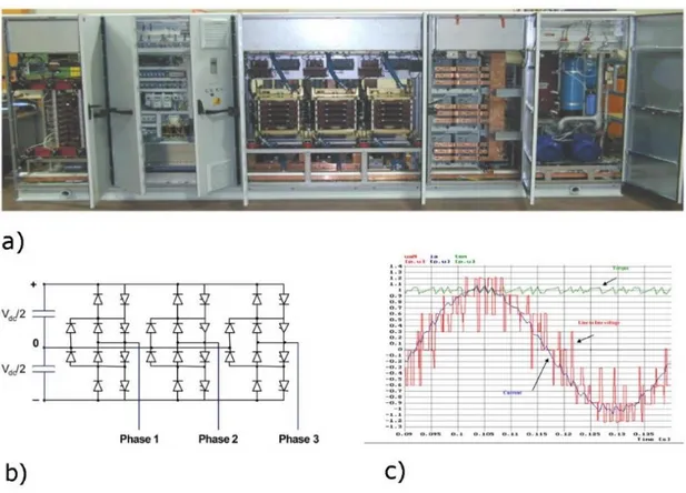
Multilevel converters can be used, these are converters in which the output voltage takes three or more output values, thus improving the output waveform and its harmonic content.
Figure 24 shows a three-level source voltage-drive diagram (Integrated Gate Commutated Thyristors) for a 3.3 kV MV system, and the related output quantities.
Figure 24- a) 3.3 kV Integrated Gate Commutated Thyristors Drive b) Drive Architecture c) Output Trend
Table 2 summarizes the drivers’ characteristics seen previously; the first column reports the characteristics related to the engines’ direct insertion into the network.
29
Table 2- Drive Features
DOL10 SCR DC Motor
Drive cycle converter
11 CSI12 (LCI) VSI13 DTC
Insertion current 5 ∙ 𝐼𝑛 ≈ 0 ≈ 0 ≈ 0 ≈ 0
Starting torque 2÷3 x nominal
torque ≈ 0 ≈ 0
Up to a 50%
nominal torque ≈ 0 Power consumption, for low
thrust
≈ 15% nominal
power ≈ 0 ≈ 0 ≈ 0 ≈ 0
Current, for low thrust 45÷55% della
nominale f (torque) f (torque) f (torque) ≈ 0 Power factor, at nominal load ≈ 0.85 > 0.9 > 0.76 > 0.9 > 0.95
Variation of the power factor
with the load (cosφ) 0.15 ÷ 0.85 (non linear) 0 ÷ 0.9 (proportional speed) 0 ÷ 0.76 (proportional speed) 0 ÷ 0.9 (proportional speed) > 0.95 (constant) Dynamic response (power,
torque)
3÷5 sec (propeller pitch
control)
<100 ms <100 ms lower <10 ms
Pulsations of torque nothing smooth smooth pulsating smooth
Zero push transition Smooth if negative thrust is
allowed
Non continuous smooth pulsating smooth
Full load efficiency high low high high high
Harmonic distortion a - low speed / thrust - high speed / thrust
None None f (torque) f (torque) f (torque) f (torque) f (torque) f (torque) None f (power) Short circuit contribution 5x nominal
power No No No No
Changes for adaptation to
some types of engines - Several Several Yes No
Switch presence No Yes No No No
1.8 Regulatory requirements and naval registers relating to environmental conditions
The environmental conditions that arise on board the ship are very critical, high humidity and temperatures, mechanical stresses, such as vibrations as a result of the ship’s movement or of mechanical origin (engines first), all contribute to creating an extremely heavy and aggressive environment that requires the use of particularly robust electrical equipment.
For ships without navigation restrictions the reference temperature for enclosed spaces varies from + 5° C to + 45° C, for ships with navigation in specific areas (e.g. outside tropical areas) the maximum operating temperature assumed is equal to 40° C. Standard provisions for humidity conditions provide a value of 95% at 55° C.
The required level of vibrations varies in relation to the location of the electrical component. For installations in command and control stations, on exposed bridges or in entertainment spaces of the various rooms on board, the field verification required for the responsiveness to vibrations varies from 2 Hz to 13.2 Hz with a width of 1mm and from 13.2 Hz to 100 Hz with an acceleration of 0.7g
(1g = 9.8 m/s2). Power quality parameters such as voltage variations between +6% and -10%, and
+/-5% frequency values are also provided by standards. For the harmonic content of systems without main loads, controlled by power converters through synchronous generators, the total level of harmonic distortion of the voltage must not exceed 5% and the single harmonic must not exceed 3% of the fundamental. In the presence of loads controlled by static converters the single harmonic does
not exceed 5% of nominal voltage up to the 15th order of harmonics and the total level of harmonic
distortion admitted not must exceed 10%. For the presence of those equipment which allow the
10 Asynchronous motor coupled with orientable propeller 11 Synchronous engine
12 Synchronous engine
![Figure 2 reports a timeline listing the main milestones in marine vessels power systems [6]](https://thumb-eu.123doks.com/thumbv2/123dokorg/2894886.11524/12.892.132.795.213.622/figure-reports-timeline-listing-milestones-marine-vessels-systems.webp)
![Figure 31 shows the arrangement of the propulsion system and the relative dimensions inside the hull [28]](https://thumb-eu.123doks.com/thumbv2/123dokorg/2894886.11524/42.892.136.782.346.509/figure-shows-arrangement-propulsion-relative-dimensions-inside-hull.webp)