Università degli Studi di Ferrara
DOTTORATO DI RICERCA IN FISICA
CICLO XXVIII
COORDINATORE Prof. Guidi Vincenzo
LAUE LENSES TO FOCUS X- AND GAMMA-RAY BEAMS
FOR MEDICAL APPLICATIONS
Settore Scientifico Disciplinare FIS/01
Dottorando Tutore
Dott. Paternò Gianfranco Prof. Guidi Vincenzo
I G. Patern`o, V. Bellucci, R. Camattari and V. Guidi - Design study of a Laue lens for
nu-clear medicine - Journal of Applied Crystallography (2015) 48:125-137, 10.1107/S1600576714026235 II G. Patern`o, M. Marziani, R. Camattari V. Bellucci, A. Mazzolari, M. Gambaccini and
V. Guidi - Laue lens to focus an X-ray beam for radiation therapy - in press in Journal of Applied Crystallography (2016)
III R. Camattari, G. Patern`o, A. Battelli, V. Bellucci, P. Bastie and V. Guidi - High-efficiency focusing of hard X-rays exploiting the quasi-mosaic effect in a bent germanium crystal - Journal of Applied Crystallography (2014) 47:799-802, 10.1107/S1600576714005056 IV A. Mazzolari, R. Camattari, V. Bellucci, G. Patern`o, C. Scian, G. Mattei and V. Guidi
- Manufacturing of advanced bent crystals for Laue Optics for Gamma ObservationS (LOGOS) - Nuclear Instruments and Methods in Physics Research B 355 (2015) 297-300, http://dx.doi.org/10.1016/j.nimb.2015.03.048
V V. Bellucci, R. Camattari, V. Guidi, A. Mazzolari, G. Patern`o, G. Mattei, C. Scian and L. Lanzoni Ion implantation for manufacturing bent and periodically bent crystals -Applied Physics Letters 107, 064102 (2015), http://dx.doi.org/10.1063/1.4928553 VI R. Camattari, G. Patern`o, V. Bellucci, A. Mazzolari, M. Romagnoni, and V. Guidi
- Optical elements for hard X-rays based on sandblasting - submitted to Journal of Applied Crystallography (2016)
Articles published during the Ph.D. as side products of this
thesis.
• R. Camattari, G. Patern`o, V. Bellucci and V. Guidi - Quasi-mosaicity of (311) planes in silicon and its usage in a high-focusing Laue lens - Experimental Astronomy (2014) 38:417-431, 10.1007/s10686-014-9429-7
• R. Camattari, G. Patern`o, V. Bellucci, V. Guidi, M. Jentschel and P. Bastie - High-efficiency diffraction and focusing of X-rays through asymmetric bent crystalline planes - Journal of Applied Crystallography (2015) 48:297-300, 10.1107/S1600576714024960
Introduction 1 1 Diffraction of high-energy radiation in crystals 5
1.1 Structure of crystals . . . 5
1.2 Generalities on diffraction in crystals . . . 7
1.3 Diffraction in perfect crystals . . . 7
1.4 Diffraction in mosaic crystals . . . 10
1.5 Diffraction in crystals with curved diffracting planes . . . 11
2 Usage and fabrication of bent crystals 15 2.1 Usage of bent crystals . . . 15
2.1.1 Bending techniques . . . 15
2.1.2 CDP and quasi-mosaic crystals . . . 16
2.2 Innovative methods to fabricate bent crystals . . . 18
2.2.1 Deposition of a carbon fibre film . . . 18
2.2.2 Ion implantation . . . 21
2.2.3 Sandblasting . . . 26
2.3 Focusing capabilities of a bent crystal . . . 31
3 Laue lenses for nuclear medicine 37 3.1 Motivations . . . 37
3.2 Lens design principles . . . 39
3.2.1 Geometry of the system . . . 39
3.2.2 Efficiency calculation . . . 42
3.2.3 Point Spread Function calculation . . . 45
3.2.4 Field Of View estimation . . . 49
3.2.5 Response of the lens vs. energy . . . 49
3.5 Lens-detector coupling . . . 57
3.6 Images provided by the proposed lens in realistic cases . . . 59
3.6.1 Complex activity distribution within the FOV of the lens . . . 59
3.6.2 Effect of crystal misalignments . . . 63
3.6.3 Scan of an extended source . . . 64
4 Laue lenses for radiation therapy 67 4.1 Motivations . . . 67
4.2 Lens design principles . . . 70
4.3 LAUETHER simulations . . . 75
4.3.1 The LAUETHER code . . . 76
4.3.2 Proposal of a Laue lens for radiotherapy . . . 77
4.4 GAMOS simulations . . . 81
4.5 Scan of an extended tumour mass . . . 87
5 Prototype of a Laue lens for radiation therapy 91 5.1 Design and assembling of the prototype . . . 92
5.2 Test of the prototype . . . 94
Conclusions 101 Appendices 107 A Theory of linear elasticity in crystals 107 B Features of diffraction of high-energy radiation in CDP crystals 113 B.1 Modelization of the diffraction process in the LAUENM code . . . 113
B.2 Focusing/defocusing properties of CDP crystals . . . 117
B.3 Variation of the spacing between the diffracting planes in a CDP crystal . . . 120
Cancer is a leading cause of death worldwide, accounting for 8.2 million deaths in 2012 [1]. Cancer mortality can be reduced if cases are detected and treated early. Some of the most common cancer types, such as breast cancer, cervical cancer, oral cancer and colorectal cancer have high cure rates when detected early and treated according to best practices. However, a tumour in a early stage of evolution has a very small size and could be located near radiosensitive organs. Therefore, high-resolution techniques are required to accurately detect and effectively treat such small tumours.
Going deeper in understanding the processes of carcinogenesis would represent a further step forward in the fight against cancer. A non-invasive imaging system that allows in vivo assessment of biological and biomolecular interactions would permit to get insight into the complex events contributing to the induction of DNA damage, repair, mutagenesis, and carcinogenesis [2]. While these kind of studies can be performed using conventional radionuclide imaging techniques such as single-photon emission tomography (SPECT) and positron emission tomography (PET), these techniques are inherently limited to spatial resolutions of 1-2 mm [3]. The image resolution could be increased by using an optics capable of focusing the γ-ray emitted by radionuclides. As the index of refraction of all materials is . 1 for high-energy photons, common refractive optics can not be used [4]. A possible solution is to exploit the total external reflection of γ-rays that take place when they impinge on the surface of a medium at a small glancing angle. A radionuclide imaging system based on such kind of reflective optics was developed for small animals [5, 6]. This device is theoretically capable of achieving sub-millimetre spatial resolution with 1 × 10⁻⁵ efficiency for γ-photons at 27.5 keV emitted by 125I. However, since the critical angle for total reflection is inversely proportional to the photon energy and a medical device has to be as compact as possible, this approach is not suitable for performing radionuclide studies exploiting γ-lines at higher energy, such as the intense line at 140.5 keV emitted by the
99mT c, which is the most used general purpose radioisotope.
ensemble of crystals, usually disposed as concentric rings, that exploit Bragg diffraction in Laue configuration to focus a relatively large number of the photons emitted by a high-energy source into a small focal spot [7]. Due to focusing, a precise mapping of the radioactivity distribution inside a small volume can be obtained. Therefore, this device could be exploited to perform high-resolution radionuclide imaging both for small-animals and humans.
The same optical device can be also used for treating tumour through radiotherapy. Radiotherapy consists in imparting a radiation dose to a target volume in order to destroy cancer cells. Any radiotherapy treatment aims to maximize the dose to the tumour, minimiz-ing at the same time the irradiation of neighbourminimiz-ing healthy tissues. Among radiotherapy treatments, hadron therapy uses charged particles beams, namely protons or positive ions, to achieve the aforementioned goal. Indeed, they have a finite range of penetration in a tissue and a high amount of energy released at the end of their track. However, hadron therapy is not easily available, because it requires very large investments in equipment and huge machines [8]. Thus, only a limited number of patients can access to the high-quality treatment provided by hadron therapy. Conventional radiotherapy is more accessible since it relies on compact electron linear accelerator producing photon beams in the MeV energy range to reach the tumour and spare the skin. However, such technique is not comparable with the hadron therapy in terms of dose deposition accuracy. A device capable of focusing X-rays would allow concentrating the dose toward the tumour sparing at the same time the surrounding normal tissues. Indeed, due to focusing, the photon flux would increase with the penetration depth and would reach the maximum at the focal point. The combination of this effect with the photon absorption by the tissues would give rise to a depth-dose profile showing a pronounced peak at the focal depth and a rather rapid fall-off beyond this point. This dose distribution is somewhat similar to that achievable with hadron therapy. The phenomenon of diffraction occurring in the crystals composing a Laue lens can be exploited to focus an X-ray beam. In particular, it is possible to use a conventional X-ray tube with peak voltage up to 250 kV as a source of radiation and exploit a Laue lens to concentrate as much radiation as possible toward the focal point of the lens, where the tumour mass is located. Thus, it would be possible to reach a high precision in the dose delivery with an equipment orders of magnitude less expensive if compared to the cost of a facility for hadron therapy and even less expensive than the equipment for traditional radiotherapy based on MeV X-ray beams.
The work presented in this thesis concerns the study and the realization of Laue lenses devoted to medical applications. The thesis is divided into 5 chapters plus 2 appendices. The first chapter deals with the basic concepts of diffraction of high-energy radiation in
various types of crystals, i.e., perfect, mosaic, and curved diffracting planes (CDP) crystals. The second chapter contains an overview of the usage of bent crystals in modern physics and of the techniques used to fabricate them. Some innovative bending methods devel-oped at the Sensor and Semiconductor Laboratory (SSL) of Ferrara in the framework of the INFN-LOGOS project are described in detail. Furthermore, an experiment devoted to the demonstration of the focusing capabilities of a bent crystal is described. In the third chapter, a detailed study and the design principles of a Laue lens for nuclear medicine are presented. The study was carried out through a specifically written ray tracer, called LAUENM. The imaging capabilities of the designed lenses were assessed with diverse configurations of the source. In these cases, the images recorded by a real detector were simulated. The fourth chapter aims to demonstrate the effectiveness and versatility of a system for radiation ther-apy based on a Laue lens. Two series of simulations were carried out. The first series was performed employing a custom made Monte Carlo software, called LAUETHER to calculate the phase space of the diffracted photons in a plane at an arbitrary distance from the lens. The second series of simulations was performed through GAMOS, a Monte Carlo particle tracking code, to calculate the dose distribution inside a voxelized water phantom due to the beam diffracted by a proposed Laue lens. Various conditions of irradiation were considered. The fifth chapter is dedicated to describe a first prototype of Laue lens for radiotherapy developed at the SSL. The result of an experimental test performed at the LARIX labora-tory of Ferrara is also shown and a comparison with the simulations is given. In Appendix A, a brief treatment of the theory of linear elasticity is provided. Appendix B contains a description of the algorithms used in the LAUENM code and the demonstration of the focusing/defocusing properties of CDP crystals.
Diffraction of high-energy radiation
in crystals
1.1
Structure of crystals
An ideal crystal can be viewed as the infinite repetition of identical structural units, called basis. The spatial distribution of the basis can be described through a set of points called lattice. It is possible to define the lattice using three vectors, a1 a2 a3, such that the
arrangement of the atoms in the crystal is the same when viewed at the point r or at each point r′,
r′ = r + u
1a1+ u2a2+ u3a3, (1.1)
where u1 u2 u3 are three arbitrary integer numbers. Vectors ai represent the lattice
con-stants. The volume built on these vectors is called unit cell. The unit cell is therefore the smallest unit of volume that contains all of the structural and symmetry information to build-up the macroscopic structure of the lattice by translation. The positions of the atoms inside the unit cell are described by the set of atomic positions measured from a lattice point. Lattice and base define the crystal, as the basis indicates the positions occupied by different atoms in the cell and their type, while the reticle provides the information on the periodicity of the crystal. The fundamental characteristic of crystals is their invariance, for appropriate translations and rotations, of their physical properties, such as the optical, chemical, electrical, and elastic properties. The space group that identifies each type of crystal defines these degrees of freedom. Base and lattice are not uniquely defined, there are endless equivalent combinations to describe the same crystal. A cell is called primitive if it contains only one lattice point.
Figure 1.1: Conventional cubic cell of silicon.
the tetrahedral bond between the atoms of the crystal. Each atom forms covalent bonds with 4 identical neighbouring atoms. The bonds are characterized by the same length and angular separation and define a tetrahedral structure. However, such type of structure involves some of the features of the cubic symmetry. Indeed, it can be described through a face-centred cubic (fcc) lattice with bi-atomic basis composed of identical atoms positioned at the point of coordinates (0,0,0) and (a/4,a/4,a/4), where a is the lattice constant (5.43 ˚
A for Si) and identifies the side of the conventional cubic cell (Fig. 1.1). This crystalline structure can also be represented as two interpenetrating fcc lattices shifted with respect to one another by the vector (a/4,a/4,a/4).
The crystallographic directions and planes are fictitious entities that connect the atoms in a crystal. Depending on the density of atoms and on the type of bonds, the chemical-physical properties may change along different directions and planes. Directions and planes can be identified within a crystal through three integers hkl, called Miller indices. They are defined as the reciprocals of the fractional intercepts which the lattice plane makes with the vector defining the conventional cell. If we consider a crystal with a cubic conventional cell and the planes make intercepts of a/h, a/k, a/l with the axes, then the Miller indices of that plane are (hkl), written in parentheses. If a plane is parallel to a given axis, its fractional intercept on that axis goes to infinity and the corresponding Miller index is taken as zero. If a fractional intercept is negative, it is labeled with an overlined symbol. If the Miller indices [hkl] are shown in square brackets, they give the direction of a vector orthogonal of the plane with the same indices. As an example, in Fig. 1.1 a lattice plane and some directions are shown.
1.2
Generalities on diffraction in crystals
X- and γ-ray diffraction is a coherent effect carried out by parallel atomic planes within a crystalline material. Incident photons are scattered by the electrons in the crystal. Reflected waves interfere constructively, giving rise to a diffracted beam, provided that their paths through the crystal leads to a phase shift which is multiple of the wavelength. This condition occurs if the Bragg’s law is satisfied:
2dhklsinθB= λ, (1.2)
where dhkl is the spacing between atomic planes, θB the angle subtended by the incoming
photon trajectory and the diffracting lattice planes, and λ the wavelength of the radiation. The Bragg angle, θB, depends on the orientation of the lattice planes. Indeed, for a crystal
having a cubic conventional cell, such as Cu, GaAs, Si, or Ge, the spacing between planes can be expressed as
dhkl=
a √
h2+ k2+ l2, (1.3)
where a is the lattice constant of the crystal and h, k, l are the Miller indices of the planes. Since λ = hpc/E, where hp is the Planck’s constant, c the speed of light in vacuum, and E
the energy of the radiation, by combining equations (1.2) and (1.3), it follows sinθB =
hpc√h2+ k2+ l2
2aE . (1.4) Two diffraction geometries are possible. In the first case, called Bragg (reflection) geom-etry and depicted in Fig. 1.2.a, the diffracted beam comes out from the same crystal surface on which the incident beam impinges. Conversely, in the Laue (transmission) geometry, depicted in Fig. 1.2.b, the diffracted beam comes out from the surface opposite to that onto which the incident beam impinges. For high-energy photons, such as those emitted by a radiotracer, the Bragg angle is very small and the crystal has to be large to diffract even a small-size beam. For this reason, the Laue geometry represents a more convenient choice.
1.3
Diffraction in perfect crystals
The diffracted beam intensity depends on the crystal features and can be obtained from the dynamical theory or from the kinematic theory of diffraction [9]. The dynamical theory, as developed by Darwin, takes into account the interaction of X-rays with matter by solving recurrence equations that describe the balance of partially transmitted and partially reflected
Figure 1.2: Diffraction geometries. a) Bragg geometry: the diffracted beam comes out from the same crystal surface on which the incident beam impinges. b) Laue geometry: the diffracted beam comes out from the surface opposite to that on which the incident beam impinges.
waves at each lattice plane [10, 11]. On the contrary, the kinematic theory assumes that each photon is scattered only once. The total diffracted amplitude is simply obtained by adding the individual amplitudes diffracted by each diffracting centre, taking into account only the geometrical phase differences between them and neglecting the interaction of the radiation with matter. Even if the kinematic theory is less rigorous than the dynamical theory, it gives correct results when a thin perfect crystal or a highly-distorted crystal is considered. An exhaustive treatment of the subject, in both perfect and distorted crystals, can be found in specialized books [4] or in review articles [12, 13, 14]. Here, only the concepts that are relevant for the study of a Laue lens are recalled.
The reflectivity of a crystal is defined as the ratio of the diffracted beam intensity over the incident beam intensity. Instead, diffraction efficiency is defined as the ratio of the diffracted beam intensity over the transmitted beam intensity when no diffraction occurs.
For a radiation of energy E and a crystal with lattice planes (hkl), equation (1.4) provides the incidence angle θ at which diffraction occurs. Actually, both kinematic and dynamical theories predict a range around the Bragg angle θB for which the intensity of the diffracted
beam is different from zero. If we consider a perfect crystal under Laue symmetrical ge-ometry1, the rocking curve, i.e. the reflectivity (or the diffraction efficiency) plotted as a
function of ∆θ = θ − θB shows a narrow peak (see Fig. 1.3). Its width at Half Maximum
(FWHM) is called Darwin width δ
δ = 2dhkl Λ0
, (1.5)
Figure 1.3: Rocking curves for flat Ge crystal with a thickness of 1 mm and using (111) lattice planes to diffract 140.5 keV photons.
where Λ0 is defined as the extinction length
Λ0 =
πVccos θB
reλ|C||Fhkl|
, (1.6)
Vc being the volume of the crystal elementary cell (Vc = a3 for a cubic cell), re the classical
electron radius, λ the wavelength of the radiation, C the polarization factor, and Fhkl the
structure factor. For an unpolarized beam, the polarization factor is C = (1 + cos2θ B)/2.
The structure factor quantifies the scattering efficiency of an elementary cell of the crystal, by taking into account the repartition of electrons in space and the vibration of lattice ions via the so-called Debye-Waller factor [15].
The Darwin width defines the angular acceptance of a flat crystal, as well as the energy bandwidth since Bragg’s law, under small-angle approximation, gives an inverse proportion-ality between diffraction angle and photon energy. At the energies of interest for medical applications (50 - 250 keV), typical values for δ are of the order of 1 arcsec. Furthermore, because of the re-diffraction of the beam, the diffraction efficiency of a thick flat crystal can be expressed as
ηD =
1
2(1 + (2∆θ/δ))2, (1.7)
therefore the reflectivity of a thick flat crystal is pinned to 1/2 [9]. A crystal can be regarded as thick if T0 ≫ Λ0, T0 being the thickness of crystal traversed by radiation. Since in our
case Λ0 is small, this condition is almost always fulfilled. The integrated reflectivity is the
integral of the reflectivity over the angular acceptance (and energy bandwidth) of the crystal [16]. Since this quantity results to be very poor for a flat perfect crystal, different types of crystals have been considered by the scientific community for the applications and in
Figure 1.4: Sketch of a mosaic crystal.
particular for the realization of a Laue lens. Their features are summarized in the next sections.
1.4
Diffraction in mosaic crystals
Unlike an ideal crystal, a real crystal presents imperfections due to its growth condition, and it can be better modeled through the Darwin’s Model [15]. This model, known also as mosaic model, regards the crystal as an ensemble of microscopic ideal crystals, the crystal-lites, slightly misaligned to each other (see Fig. 1.4) according to an angular distribution, which is usually a Gaussian function
W (∆θ) = 2√ ln 2 π 1 me −ln 2(m/2∆θ )2 . (1.8)
The FWHM of this distribution m is called mosaicity, or mosaic spread, of the crystal. The reflectivity, under symmetric Laue condition, is
R = 1 2(1 − e
2σT0)e−µT0/ cos θB, (1.9)
T0 being the thickness traversed by the beam, µ the linear absorption coefficient of the
crystal, and
Q is the integrated intensity diffracted by an individual crystallite per unit of thickness. From the dynamical theory of diffraction, Q can be written as
Q = π
2d hkl
Λ20cos θB
f (A). (1.11) Under small-angle approximation, which is valid above 100 keV, the function f (A) can be written as
f (A) = 2I0(2A)
2A . (1.12) I0 is the integral, from 0 to 2A, of zero-order Bessel function. A is defined as
A = πt0 Λ0cos θB
, (1.13)
t0 being the thickness of crystallites. f (A) is approximately 1, which is its maximum value,
when t0≪ Λ0, namely when the dynamical theory tends to the kinematic theory.
The reflectivity of a mosaic crystal is the product of two terms. The first one is the diffraction efficiency of the crystal, the second one takes into account the absorption of the beam. As can be seen by the equation (1.9), reflectivity peaks at ∆θ = 0. The peak height is at most 1/2 as in the case of a perfect crystal.
The FWHM of the rocking curve, Ω, is proportional to the mosaicity of the crystal and can be written as
Ω = m √
− ln(−α1ln(12(1 + e−α)))
ln 2 , (1.14) where α is a dimensionless coefficient given by
α = 4π2√ ln 2 π
dhklT0
Λ20m . (1.15) Even though peak reflectivity is at most 1/2, a mosaic crystal with large mosaicity (it can be several tens of arcsec) may exhibit a large integrated reflectivity. For this reason, such crystals were chosen for the realization of the first prototypes of Laue lens for nuclear medicine [17, 18].
1.5
Diffraction in crystals with curved diffracting planes
Another type of crystal is the so-called Curved Diffracting Planes (CDP) crystal. In a CDP crystal, a stress induces a curvature in the whole lattice structure according to the elastic properties of the material. Due to the curvature, there is an angular dispersion of
Figure 1.5: Diffraction in CDP and perfect crystals. a) In a CDP crystal, due to the continuous change of the incident angle, re-diffraction is unlikely. b) In a perfect crystal the beam is reflected many times, limiting the reflectivity to 50%.
the lattice planes within the crystal. The continuous change in the orientation of the lattice planes makes it unlikely to have re-diffraction inside the crystal and the reflectivity limit of 50% disappears (Fig. 1.5). Thus, CDP crystals have the potential to achieve a better performance with respect to both perfect and mosaic crystals.
There are many ways to fabricate a CDP. The easiest one is by means of an external de-vice (holder) that applies a bending moment to the crystal [19]. This method has been in use since decades for the realization of high-efficiency monochromators employed in synchrotron high-energy X-ray beamlines [20, 21]. However, the use of a holder implies additional weight and space-occupation. These problems represent a severe limitation to the use of such a crystal as a component of a Laue lens for medical applications. Thus, the crystal curvature is required to be self-standing. For this purpose, various methods have been proposed by the scientific community. An overview of the most used and the most innovative techniques are reported in chapter 2.
Diffraction in curved crystal can be studied through Takagi-Taupin’s equations [22, 23]. They are hyperbolic partial derivative equations obtained from Maxwell’s equations in a deformed periodic medium. In the general case, these equations cannot be solved explicitly and a numerical approach has to be used. Alternatively, for slightly curved crystal, the so-called PPK theory can be adopted. Such theory, based on geometrical optics principles, has been developed independently by Penning and Polder [24], and by Kato [25]. In the
PPK theory the distortion of the diffracting planes is described by the strain gradient β, β = Λ0 cos2θ B ∂2(h · u) ∂s0∂sh , (1.16)
where s0 and sh are units vectors, parallel to the incident and to the diffracted beams
respectively. h is the reciprocal lattice vector of the reflection hkl and u the displacement vector. If the curvature of a crystal is uniform, it is possible to demonstrate [26] that the strain gradient assumes the simpler form
β = Ω T0δ/2
, (1.17)
Ω being the angular distribution of the lattice planes, T0 the thickness of the crystal, and δ
the Darwin width given by equation (1.5). The angular distribution of the lattice plane is directly proportional to the crystal curvature. Indeed, it is
Ω = T0 RC
, (1.18)
where RC is the radius of curvature of the crystal.
The rocking curve of a curved crystal follows a rectangular distribution with width Ω. The height of the plateau, which corresponds to the peak reflectivity, depends on the curva-ture of the diffracting planes as well. In the general case, reflectivity cannot be expressed in a closed-form. However, for a highly-curved crystal, an extension of the PPK theory exists that provides the reflectivity under Laue symmetric condition for diffraction [26]. It holds
R = (1 − e −π2dhkl Λ20 T0 Ω )e−cos θBµT0 . (1.19)
A crystal can be regarded as highly-curved when the following condition for the strain gradient is met
β > βc =
π 2Λ0
. (1.20)
Such condition is fulfilled if the radius of curvature of the diffracting planes RC is smaller
than the critical value RCc = 4Λ0/πδ.
If RC > RCc, a multi-lamellar model can be used for the calculation of the crystal
diffraction efficiency [27]. A multi-lamellar model which takes into account the re-diffraction of the beam is reported in [28]. Such model merges the results provided by equation (1.19) for highly-curved crystals with the results provided by the dynamical theory for flat thick crystals.
Figure 1.6: Theoretical rocking curves for a mosaic and a CDP Ge crystal with the same thickness T0 = 1 mm and angular acceptance Ω = 20 arcsec and using (111) lattice planes
to diffract 140.5 keV photons. a) CDP crystal with radius of curvature RC = 10.3 m. b)
Mosaic crystal with mosaicity m = 13.6 arcsec.
In Fig. 1.6 the rocking curves for a mosaic and a CDP crystal with the same angular acceptance are compared. Peak reflectivity of a CDP crystal, as calculated by equation (1.19), does not suffer from the 50% limitation. Hence, CDP crystals can have a very high integrated reflectivity, resulting very good candidates for the realization of a Laue lens.
Usage and fabrication of bent
crystals
2.1
Usage of bent crystals
Manufacturing and development of bent crystals are making progress in different physical fields. Indeed, bent crystals can be used as optical elements for neutron, X- and γ-rays as well as optical elements for the manipulation of charged particle beams. In fact, by exploiting diffraction of high-energy radiation in bent crystals, many modern applications and tools have been developed, such as monochromators for ray beamlines [20], hard X-ray focusing system for astrophysical [29] and nuclear medicine [18] purposes, and neutron beam controller with wide angular acceptance [30]. On the other hand, owing to the strong electric field generated by ordered atoms in a bent crystal, it is possible to manipulate charged particle trajectories via coherent effects such as channeling and volume reflection [31, 32]. Bent crystals have already been proposed to be used in collimation systems [33], for beam steering [34], and extraction [35]. Radiation emission due to curved trajectories of charged particles in bent crystals was studied in order to yield photon production through bremsstrahlung, channeling radiation, parametric X-ray radiation (PXR), and undulator use [36].
2.1.1 Bending techniques
In sight of the great interest by these scientific communities, several techniques for pro-ducing proper curved crystals have been developed, each of which has positive and negative aspects. One of the first methods that was used for bending consists is the use of a mechan-ical mean, i.e., by deforming a crystal through an external device [19, 37]. Using an holder
Figure 2.1: (a) geometry 1. (b) geometry 2. Red arrows represent an X-ray beam. Courtesy of Camattari [43].
for bending can be an optimal solution unless there are limitations due to constraints as encumbrance, weight, or miniaturization. In such latter cases, self-standing bent crystals are mandatory. A self-standing bent crystal can be obtained by applying a thermal gradient to a perfect crystal [38]. A bent crystal can also be obtained by concentration-gradient tech-niques, i.e. by growing a two-component crystal with graded composition along the growth axis [39]. These techniques have reported good results during experiments; however, such bent crystals are not easy to manufacture, thus they are not suitable for mass production. A self-standing curved crystal can be obtained by a controlled surface damage through a mechanical process performed on one side of a crystal, such as the lapping process [40] and the “grooving method” [41]. These technique are suitable for mass production, but cause non-negligible damage in the crystals.
Within the frame of the INFN-LOGOS project, various new approaches have been de-veloped at Sensor and Semiconductor Laboratory (SSL) of Ferrara to fabricate self-standing bent crystals. The most promising for the realization of optical elements for a Laue lens are based on carbon fibre deposition, ion implantation and sandblasting. The details of these method are exposed in the next section. Before that, the concept of quasi-mosaicity is introduced, because of its importance in modern physics [42].
2.1.2 CDP and quasi-mosaic crystals
Crystals with curved diffracting planes can be exploited to diffract a photon beam in Laue condition according to two different configurations. In the first one, shown in Fig.
Figure 2.2: Schematic representation of a cross section of a Laue lens based on QM crystals. Gray rectangles represent the crystals. The primary curvature leads to a secondary curvature of the planes affected by quasi-mosaicity. In this configuration the QM diffracting planes are perpendicular to the main surface of the plates. The primary curvature allows focusing diffracted radiation onto the focal plane, while the QM curvature increases the integrated diffraction efficiency. Courtesy of Camattari [43].
2.1.a and called geometry 1, the crystals are oriented with their major faces “parallel” to the photon direction and are bent directly along the side traversed by the photon beam. In the second configuration, shown in Fig. 2.1.b and called geometry 2, the samples expose their largest surface to the photon flux. In this case, the curvature of the diffracting planes is obtained exploiting the quasi-mosaic (QM) effect, which is an effect due to the crystal elastic anisotropy. Under very specific orientations, as a crystal is bent to a primary curvature by external forces, another curvature (secondary curvature) arises within the crystal, i.e., the QM curvature [44]. This effect is fully explained by the theory of linear elasticity in an anisotropic medium, a brief treatment of which is presented in Appendix A. Crystals exploiting planes bent through the QM effect to diffract a photon beam are called “QM crystals”.
A Laue lens composed of QM crystals is an arrangement of curved plates whose primary curvature lies on a spherical cap of radius RP, while the QM curvature allows diffraction
with CDPs. Due to Bragg diffraction, focusing of each QM sample converges on a focal spot at a distance f = RP/2 on the symmetry axes of the cap (see Fig. 2.2). This types of Laue
lens is best suited for an astrophysical application. In fact, in this case, the focal length f is of the order of tens of meters and the external radius of the lens can reach a few meters. As consequence, the use of CDP crystals in geometry 1 would require the fabrication and the setting up of a large number of such crystals to cover the whole lens. Quasi-mosaicity allows the focusing of the photon flux in a spot smaller than the crystal size. For a quasi-mosaic crystal, the primary curvature is responsible for focusing, while the secondary (QM) curvature increases the diffraction efficiency [45]. Thus, since the secondary curvature can control the size of the focal spot, QM crystals allow focusing with high resolution. As a result, the sensitivity of a Laue lens devoted to astrophysics could be increased [46]. In medical applications, the transversal size of the crystals has to be small because of the short focal length and therefore, Laue lenses are generally envisaged to exploit CDP crystals in geometry 1. Indeed, in chapters 3 and 4, which deal with the design study of Laue lenses for nuclear medicine and radiotherapy respectively, geometry 1 is implicitly assumed. However, in chapter 5, a prototype of Laue lens for radiotherapy exploiting QM Si crystals (geometry 2) is described. QM crystals were used because the prototype was conceived as a concept demonstrator for low energy photons. Therefore, the number of sample used was small and the their thickness traversed by the X-ray beam had not to be large.
2.2
Innovative methods to fabricate bent crystals
Three new methods aimed at producing self-standing bent crystals are presented in this section. They are based on carbon fibre deposition, ion implantation, and sandblasting re-spectively. These techniques have been developed at Sensor and Semiconductor Laboratory (SSL) of Ferrara within the frame of the INFN-LOGOS project.
2.2.1 Deposition of a carbon fibre film
The deposition of thin films may be a viable technique to obtain self-standing bent crystals with a controlled and uniform curvature [47]. The curvature induced by film de-position is already well known in microelectronics as a drawback of device manufacturing. The stress due to deposition of the most common materials has been measured, and it is usually minimized during device manufacturing. This stress can be maximized with a dif-ferent application of the knowledge of the processes. The study of this stress with the aim of inducing a large and uniform curvature in crystals is the argument of this section. Finally, experimental evidences of a silicon crystal bent through carbon fibre deposition are given.
and thick films on silicon substrates. Deposition techniques are divided in two large areas: chemical and physical depositions. Chemical depositions involves a fluid or gas precursor which undergoes a chemical change at a solid surface, leaving a solid layer. Physical depo-sition uses thermodynamic, mechanical, or electromechanical means to produce a thin film of solid. The largest part of depositions techniques are carried out at elevated tempera-tures. For example, dissociation of the precursors used in chemical depositions are typically reached placing the sample in a heated reaction chamber. In physical deposition, instead, the material to be deposited is placed in an energetic, entropic environment, so that parti-cles of material escape from its surface. Facing this source is a cooler surface which draws energy from these particles as they arrive, allowing them to form a solid layer. In order to allow the particles to travel as freely as possible, the whole system is kept in a vacuum depo-sition chamber. As a consequence of cooling of the sample from the depodepo-sition temperature to room temperature, thermal stress generates in the film and in the substrate, causing a permanent deformation of the sample.
Provided that the stress in the substrate and in the deposited film are not too high to cause delamination of the film from the substrate or even cracks in the film or in the sub-strate, deposition of thin or thick films allows achievement of a self-standing bent structure, removing the need of a mechanical bender, providing in this way space saving samples of reduced weight.
Deposition of a film of carbon fibre may be an effective method to bend thick crystals. Self-standing mono-crystals up to 5 mm thick can be produced because of the elevated value of carbon fibre stiffness. The method is expected to work with different kinds of crystals, such as silicon, germanium, gallium arsenide, copper, and others. Moreover, the method is fully compatible with mass production. Indeed, a batch of hundreds of crystal tiles takes about one hour for fibre deposition in autoclave.
Experimental method and results
A silicon crystal was bent through the deposition of a thick film of carbon fibre. The sample was shaped at the Sensor and Semiconductor Laboratory (SSL) of Ferrara, Italy, through a high precision dicing saw (DISCOT M DAD3220). Its dimensions were 20×20×5 mm. The largest surfaces were oriented as (111) planes. Such orientation was chosen because in order to have isotropic elastic constants. A photo of the sample is shown in Fig.2.3.
The carbon fibre deposition was exploited to obtain an asymmetric laminate capable of producing a curvature of the substrate. This is mainly due to the cross ply stacking sequence, whose differential shrinkage and stiffness along two perpendicular directions causes
Figure 2.3: Photo of the crystal plate. The carbon fibre film is visible. Table 2.1: Main features of the sample and the beam
Sample size (mm) 20×20×5 Thickness traversed by X-rays (mm) 20 Diffraction geometry 1 Diffracting planes (111) Beam energy (keV) 150 Beam width (µm) 50×50 Beam monochromaticity (∆E/E) 2x10⁻³
the bending of the laminate during the curing cycle. For standard composite production, this phenomenon is avoided by balancing the plies deposition, in order to avoid unwanted internal stresses, which may bend the substrate as side effect. Instead, for our purpose, we tried to maximize this effect. The film of fibres consisted of four layers of carbon fibre fabric. The direction of the fibres in each layer was perpendicular to that of the neighbouring layers. Each fibre was characterized by an intermediate elastic modulus of E = 230 GPa in weft direction and an ultra high elastic modulus of E = 600 GPa in the warp direction. The fibres were bound to the crystals with an autoclave cure cycle at a temperature of 135◦C
and pressure of 6 bar.
The curvature of the sample was tested through hard X-ray diffraction at beamline ID15A of the European Synchrotron Radiation Facility (ESRF, Grenoble, France). The beam was set at the highest energy with enough luminosity, namely 150 keV, whereas the beam width was 50×50 µm2 wide. A monochromator was used to obtain a resolution of ∆E/E = 2x10⁻³. The sample and beam parameters are listed in Tab.2.1.
The characterization of the samples was carried out by performing rocking curves (RCs), namely by recording either the transmitted or diffracted beam intensity while the crystal was being rotated in the beam around the position where the Bragg condition was satisfied. The full width at half maximum (FWHM) of the RC was a direct measurement of the angular distribution of the diffracting planes. Fig.2.4 shows the experimental result.
Figure 2.4: Experimental result. Filled red circles plot the intensity of the transmitted beam, whereas empty blue circles plot the intensity of the diffracted beam.
The angular spread Ω, namely the FWHM of the RC, is 72± 2 arcsec. Since the traversed length L was 20 mm, the radius of curvature R of the sample is R = L/Ω ≈ 57 ± 2 m. The RC is flat-topped, which means that the sample curvature was homogeneous. The diffraction efficiency turns out to be 63±6%, which is a value not attainable with a standard mosaic crystal. Such characteristics make this sample suitable to be used as an optical element for a Laue lens. The main drawback of the proposed method is that the technique does not permit producing small bent crystals, and thus it is not suitable for the applications where miniaturized samples are required.
The sample and the experimental set-up reported here are the same as those reported in [47]. However, the samples characteristics were not completely identical. Indeed, the sample described here was bent using different carbon plies, namely the weight and the density of the carbon fibre were higher. As a consequence, a larger curvature was achieved. Here, the total thickness of the carbon-fibre film was about 600 µm. It can be concluded that it is possible to control the curvature of the sample by adjusting the parameters of the carbon fibre deposition. An analytical model, based on the linear theory of elasticity, is under development.
2.2.2 Ion implantation
Ion implantation can be exploited to produce self-standing bent crystals. Ion implanta-tion has been used in the semiconductor industry for several decades [48]. A drawback of this process for semiconductor manufacturing was the production of stress in the implanted material [49]. This early disadvantage was later turned into a technology for the correction of stresses in thin films and substrates. Implanting high-energy ions into a substrate imparts
compressive stresses, causing controllable deformation of the substrate. For example, ion implantation has been used for the correction of shape errors in X-ray stepper masks [50], X-ray mirrors [51], and MEMS (Micro Electro-Mechanical Systems) deformable mirrors [52]. Sample preparation and simulation
In this section, we describe a macroscopic monocrystalline Si plate uniformly bent by ion implantation, with self-standing curvature. The sample is 10×10 mm large and 0.2 mm thick. Si is an anisotropic material, thereby the deformation due to ion implantation may result in a non-uniform curvature even if the induced stress field was uniform. Nevertheless, (111) Si lattice planes have isotropic elastic constants. For this reason, a (111) oriented wafer was chosen for the production of the sample.
The sample was implanted using He+ at the INFN Laboratories of Legnaro (Padova, Italy). Helium ions were accelerated to an energy of 150 keV and directed normally toward the sample surface. The current density of the ion beam was 1 µA/cm2. The beam flux was found to be temporally and spatially uniform within 5% over an area of 150 mm of diameter. The dose implanted into the sample resulted 2×10¹⁶ atoms/cm2.
He+ was chosen because light ions interact with the substrate nuclei only near the stop point, thereby minimizing the lattice damage. Indeed, considering the mass and the initial energy of the ions, the main mechanism through which the ions lost energy was the interaction with the electrons [53]. SRIM [54] simulations indicate for 150 keV He+ ions in
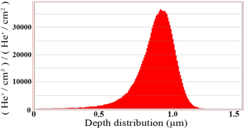
Si an initial electronic stopping of about 250 eV/nm and a nuclear one of 2 eV/nm. During this slowing-down process, ions are deflected very little and move in an almost straight line, causing few dislocations in the crystalline lattice. The energy lost per unit of path is described by the Bragg curve [55], which has a peak near the final point of the trajectory where the ion velocity is low and the transferred momentum is maximum. At this point, the interactions of the implanted ions with the nuclei of the substrate become significant and the number of dislocations in the crystalline lattice increases. Under the conditions of implantation aforementioned, the depth distribution of implanted He+ ions was simulated through the SRIM program (see Fig.2.5). The ions projected range resulted Rp = 0.88 µm with a straggling of σ = 0.14 µm. When stopped, the ions cause the amorphization of the substrate and thus its swelling [56]. As a result, the implantation process is capable of imparting a sub-surface stress, creating a tensile layer buried in the substrate structure [57]. The buried layer of amorphous material extends below the sample surface within ±3σ = 0.84 µm. This layer represents 0.42% of the total volume of the crystal, namely it is a very thin layer. For this reason, the crystals can be considered “defect-free” for the applications
Figure 2.5: Depth distribution of implanted He+ ions in a monocrystalline Si substrate
simulated through the SRIM program.
that require a high lattice quality of the crystal bulk.
Fig.2.6.a shows the deformation of the sample as measured using an optical profilometer (VEECOT M NT1100). The sample resulted uniformly bent with a curvature radius of
10.5±1.0 meters. This curvature is the largest achieved in literature for a macroscopic Si sample implanted with ions under the MeV energy.
The amorphous-Si phase is metastable and may transform into crystalline-Si. The trans-formation rate is strongly dependent on temperature and presents an Arrhenius-like be-haviour with an activation energy of 2.7 eV. At temperatures below ∼300◦C, the amorphous
to crystal transition is kinetically inhibited [58]. Thus, to prove the stability of the obtained curvature, we submitted the sample to a 300◦C annealing process 3 hours long and then
we measured again the curvature, founding it unchanged. This operation was performed at SSL using a Lenton ECF 12/6 chamber furnace.
Since the amorphized portion of the sample acts as a tensile film, the Stoney formalism for an equi-biaxial plane stress regime can be applied [59]:
σf = Es 6(1 − νs) h2 s hf 1 R (2.1)
where hs and hf are the thickness of the substrate and of the tensile film, respectively. Es
and νs are the Young’s modulus and Poisson’s ratio of the substrate, σf the film tensile
stress, and R is the local radius of curvature. Since the exact value of the film thickness is not known, the integrated stress in the film S = σfhf has been used in the computation.
Since R = 10.5 m, using the Stoney’s formula it can be inferred that ion implantation induced an integrated stress S of 145.4 ± 14.0 Pa×m.
The effect of ion implantation was then simulated through Straus7 finite element (FE) package [60]. An equivalent Si layer 1 µm thick and with a tensile stress of 145.4 MPa
Figure 2.6: Square sample bent to a spherical curvature using ion implantation. The surface that did not undergo the implantation process is displayed. (a) Morphological surface of the sample measured through interferometric profilometry. (b) Same sample simulated through FE analysis.
bonded to a Si crystal 10×10×0.2 mm with the same crystallographic orientation as the manufactured sample was simulated. A net and spherical curvature was obtained, with the radius of curvature being 10.7 m (see Fig.2.6.b).
The effect of ion implantation was finally analytically calculated through AniCryDe [61], imposing a couple of perpendicular moments per unit length
M[110]= M[112] = σfhf
hs+ hf
2 , (2.2) to the crystal plate. In this case, the radius of curvature turned out to be 10.4 m.
X-ray analysis
The depth reached by the implanted ions is very small compared to the crystal thick-ness, that is 200 µm. Then, defects and dislocations do not affect the crystal bulk. In order to verify that the whole crystal structure is not altered and uniformly bent, the sam-ple was tested by X-ray diffraction using a beam that passed through the entire crystal thickness, namely in transmission (Laue) geometry. The characterization was carried out
Figure 2.7: Rocking curves by X-ray diffraction. Experimental intensities for the diffracted (blue) and the transmitted (red) beam are plotted taking into account the experimental uncertainty. The gray areas represent the expected results as calculated by taking into account the uncertainty on the radius of curvature of the sample.
by performing rocking curves (RCs).
Curved crystalline planes were selected for the diffraction experiment because, in this case, the RCs contain information related to the crystalline quality of the bulk. Indeed, the full width at half maximum (FWHM) of the RCs for a perfect bent crystal is equal to the angle subtended by the curved diffracting planes, since the Bragg condition is met within the angular range defined by the diffracting plane curvature. If the crystal quality is deteriorated, the RCs would result broadened and the diffraction efficiency would decrease with respect to the theoretical value [12]. (311) planes were chosen because they are the curved lattice planes in Laue geometry with the highest diffraction efficiency. Here, (311) planes are in asymmetric configuration, holding an asymmetry angle ϕ = 58.52◦ from the
(111) surface [62]. Thus, diffraction occurred according a configuration rotated by 58.52◦ with respect to the geometry 1.
Characterizations were performed at beamline ID15A of ESRF (Grenoble, France). A highly monochromatic and collimated beam was tuned to 150 keV by a two-reflection Laue Si (111) unbent monochromator. The monochromaticity was ∆E/E = 2×10⁻³, the beam size was 50×50 µm. Diffraction analysis is shown in Fig.2.7. The expected diffraction efficiency was calculated taking into account an ideal bent crystal. The good agreement
between experimental data and theoretical expectations indicates that the crystallographic planes are homogeneously bent and the crystallographic quality preserved. The technique here proposed is precise and suited for miniaturization, however it requires an ion implanter and does not permit to bend crystals thicker than few hundreds of µm.
As an elective application of ion implantation to obtain a deformed crystal, we envisage the fabrication of a crystalline undulator (CU). A CU consists of a crystal whose planes are periodically bent with an amplitude much larger than the interplanar spacing. Such an undulator can be exploited as a generator of electromagnetic radiation by ultra-relativistic positrons channeling in the undulated planes of the CU [36]. Indeed, ion implantation can be used to produce precise bending of perfect crystals, leaving the bulk substantially defect-free, which is a necessary condition for channeling experiments. Moreover, ion implantation can be combined to photolithographic techniques, in order to produce micrometric pattern of implanted regions. In [63], we numerically simulated a Si CU, 5 mm long, 0.2 mm thick, and 1 mm wide; the undulating period was 1 mm. The same CU was realized through the grooving method and successfully tested using a proton beam [64]. These parameters fulfil the condition for an optimal undulator in the case of 15 GeV positrons.
2.2.3 Sandblasting
Sandblasting (or simply blasting) is a mechanical process that consists in driving a stream of abrasive material against a surface. A pressurized fluid, typically compressed air, is used to propel the blasting material. Sandblasting is commonly used to smooth a rough surface, roughen a smooth surface, shape a surface, or remove surface contaminants. Here, we propose to use sandblasting for producing self-standing bent crystals. Indeed, the thin damaged layer that originates at the surface of a blasted crystalline sample acts as a tensile film able to bent the crystal bulk. The advantages of this technique are that it is suitable for mass production, it is fast and economical, it does not add any materials to the crystal, and it permits to bend from thin to thick crystals, up to several mm. The drawback is that a thin layer of the material results damaged by the process itself. In particular, this type of self-standing bent crystal would be a very good solution if used as an optical element of a Laue lens for medical purpose or as an optical element for manipulating charged particles in the cases where contaminating materials are not allowed.
Experimental method and results
Several Si crystals were prepared and machined at SSL. The samples were shaped through a high precision dicing saw (DISCOT M DAD3220) as squared tiles 10×10 mm wide, featuring
Figure 2.8: Schematic representation of the machined Si samples. Table 2.2: Characteristics of the sandblasting process
Sample material Si Sample size (mm) 10×10 Sample thickness (mm) 0.5, 1.0, 2.0
Sandblaster SAMAC
Compressed air consumption 560 lt/s @ 6 bar Blasting medium natron glass Blasting size (µm) 1 - 50 Blasting density (g/cm3) 2.3±0.3
Blasting hardness (Mohs) 6 Blasting distance (cm) ∼ 10
Blasting time (s) 120
three different thicknesses, namely 0.5, 1.0, and 2.0 mm. In particular, three samples for each thickness were produced. The crystallographic orientations of the nine samples are shown in Fig.2.8.
The deformation of the samples was obtained by sandblasting of one of the largest surfaces of the tiles. The characteristics of the manufacturing process are listed in Tab.2.2. Then, the curvature of the samples was measured by using an optical profilometer (VEECOT M NT1100) with 1 µm lateral and 1 nm vertical resolution. Since the machined surface is dam-aged, the profilometric characterization was carried out on the back face of the samples. The results of the profilometric measurements are listed in Tab.2.3.
The sandblasting process produced dislocations on the machined surface of the samples, the thickness of the damaged layer being dependent on the sandblasting process. This layer resulted in a plasticized thin film that bent the crystal. As in other contexts where a plasticized layer lays on the crystal surface, it is possible to model the layer as a compressive thin film. Indeed, the plasticized layer is capable of transferring coactive forces to the crystal bulk, thus producing an elastic strain field within the crystal. Therefore, the Stoney formalism for an equi-biaxial plane stress regime can be adopted. In order to take into
Table 2.3: Experimental and simulated results for the radius of curvature of the samples along the [111] direction.
Sample Interferometric Analytical Simulation Simulation thickness measurements calculation with Straus7 with AniCryDe
0.5 mm 6.2±0.7 m 5.1±0.2 m 5.3±0.1 m 5.1±0.2 m 1.0 mm 20.6±1.8 m 20.4±0.6 m 20.8±0.4 m 20.3±0.7 m 2.0 mm 80.0±6.3 m 81.5±2.6 m 82.5±1.8 m 81.4±2.6 m
account the anisotropic behaviour of Si crystal, the Stoney formula can be written as in [65]: σf = hs2 6(S11+ S12)hf 1 R, (2.3) where hs and hf are the thickness of the substrate and of the compressive film respectively,
σf the film stress, R the curvature radius of the sample, and Sij are the components of
compliance tensor for anisotropic material referred to the (x, y, z) Cartesian system [66]. The film thickness was not directly measurable. It was estimated to be ∼ 5 µm [67]. By fitting the experimental data with Eq.2.3, σf resulted 374±8 MPa. The effect of sandblasting
was then simulated through Straus7 finite element package. An equivalent damaged Si layer 5 µm thick and with a compressive stress of 374 MPa bonded to Si crystal tiles with the same size and crystallographic orientation as the manufactured samples was simulated. The output of the simulations is reported in Tab.2.3. The effect of sandblasting was finally evaluated using the software AnyCriDe, imposing a couple of perpendicular moments per unit length to the crystal plate Mx = My = σfhfhs+h2 f. The simulation results are reported
in Tab.2.3.
Since the simulations are in good agreement with the experimental data, the thin layer of damaged material can be appropriately considered as a compressive thin film.
X-ray analysis
To evaluate the crystalline quality, the samples were tested through γ-ray diffraction at the Institut Laue-Langevin (ILL, Grenoble, France) at DIGRA, that is a facility specifi-cally built for characterizing instrumentation for astrophysics. The γ-ray beam energy was 181.931 keV and its monochromaticity was ∆E/E ≈ 10−6. The beam flux was produced by neutron capture in a gadolinium target (157
64 Gd) inserted close to the nuclear reactor of ILL
at a temperature of about 400◦C. The beam divergence after a Si (220) monochromator was
∼ 3.5 arcsec, as measured by recording a rocking curve (RC) of the monochromator itself. The collimated beam size was 1×2 mm2. A standard electrode coaxial Ge detector with
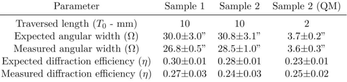
Table 2.4: Experimental and theoretical results for the rocking curves. Parameter Sample 1 Sample 2 Sample 2 (QM) Traversed length (T0 - mm) 10 10 2
Expected angular width (Ω) 30.0±3.0” 30.8±3.1” 3.7±0.2” Measured angular width (Ω) 26.8±0.5” 28.5±1.0” 3.6±0.3” Expected diffraction efficiency (η) 0.30±0.01 0.28±0.01 0.23±0.01 Measured diffraction efficiency (η) 0.27±0.03 0.24±0.03 0.25±0.02 25% relative efficiency was used.
Characterization of the samples was carried out by performing RCs. The crystals were analysed using two different geometries. In the first geometry, the beam passed through the sample along the [111] direction, traversing 10 mm of material (geometry 1). In this geometry, the curvature directly induced by the sandblasting process was measurable. In the second geometry, the beam passed through the shortest side of the crystal, i.e. along the [11-2] direction (geometry 2). In this configuration, it was possible to record the RC of the crystallographic planes bent by the quasi-mosaic (QM) effect [42]. Indeed, the (111) planes resulted bent by the QM effect, as shown in Fig.2.8.
The 2 mm thick samples were selected for X-ray analysis because they were able to show the highest reflectivity. In particular, two samples were tested in the geometry 1 (Fig.2.9.a and b), while the second sample was also measured using the geometry 2 (Fig.2.9.c).
By fitting the RCs with the dynamical theory of diffraction, it is possible to derive the sample curvature, the homogeneity of the curvature, and the quality of the crystal bulk. Indeed, the width of the RC is proportional to the bending angle of the sample and the RC peak is a measure of the crystal quality. The diffraction efficiency is given by the formula
η = 1 − e
−π2T0dhkl
ΩΛ20 , (2.4)
where T0 is the crystal thickness traversed by radiation, dhkl the d-spacing of the
diffract-ing planes (hkl), Λ0 the extinction length as defined in chapter 1 for the Laue symmetric
case, and Ω the bending angle of the curved diffracting planes. Experimental results and theoretical expectations are reported in Tab.2.4.
The results reported in Fig.2.9.c are here explained. From the theory of elasticity, the ratio between the QM curvature radius, RQM, and the superficial (primary) curvature radius
(RP = 72.2 m), is RRQMP = 2.61 for the (111) planes, thus RQM = 2.61Rp = 188.5 m [42].
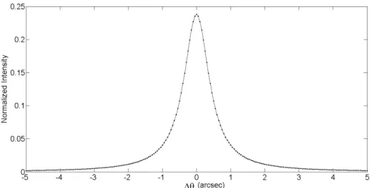
Here, the QM curvature corresponded to an angular spread of 2.19 arcsec for the (111) planes. Diffraction efficiency was expected to be 94.7%. The RCs reported in Fig.2.9.c
Figure 2.9: Rocking curves; black dots represent the diffracted beam, red dots the trans-mitted beam. (a) sample 1 in the geometry 1 (primary curvature); (b) sample 2 in the geometry 1 (primary curvature): (c) sample 2 in the geometry 2 (QM curvature). Grey areas represent the theoretical expectation.
shows a peak far lower than the prediction of the dynamical theory of diffraction. However, there are some factors that have to be taken into consideration. Indeed, the measured RC was the convolution of three functions. The first function was a uniform distribution due to the diffracting QM planes, 2.19 arcsec wide and 0.947 in height. The second function represented the spread owing to the primary curvature, which was a uniform distribution 2.85 arcsec wide and 1 in height. Indeed, the beam had a finite size of 1 mm along the x direction; thus, the primary curvature resulted in a rotation of the diffracting planes by 2.85 arcsec. The third function took into account the resolution of the experimental setup, which was represented by a Normal distribution with standard deviation equal to 3.5 arcsec. As a result, the RC was a symmetric function with 3.66 arcsec as standard deviation and peak equal to 0.238. The grey area in Fig.2.9.c represents the theoretical expectation, taking into account the uncertainty on the primary curvature of the sample. The values reported in Tab.2.4 for the QM case take into account all the contributions in the convolution.
In summary, Figs.2.9.a, b, and c highlight very good agreement between theoretical expectations and experimental results; thus, the method did not compromise the quality of the crystal bulk. Therefore, the samples produced using the sandblasting method can be profitably used as X-ray optical elements and as charged particle beam steerer.
2.3
Focusing capabilities of a bent crystal
In this section, an experiment devoted to the demonstration of the focusing capabilities of a bent crystal is described. In particular, a QM Ge sample was produced through the grooving method [65] and characterized through X-ray diffraction. Exploiting the quasi-mosaic effect, it was possible to combine high intensity of the diffracted beam due to the curvature of the diffracting planes with the focusing due to the primary curvature. The focusing effect was assessed by recording on a detector the image of the sample due to the diffraction of a polychromatic and divergent hard X-ray beam.
Sample production and characterization
Production and morphological characterization of a bent Ge sample was carried out at SSL. A sketch of the sample is shown in Fig. 2.10.
A commercially available pure Ge wafer was diced to form a plate of 10×30×2 mm using a high-precision dicing saw (DISCOT M DAD3220). A permanent curvature was induced through the manufacture of a grid of superficial grooves on one of the largest surfaces of the plate. The surface grooving produced a permanent plastic deformation in a thin layer of the
Figure 2.10: Sketch of the Ge sample. Crystallographic orientations and grooves are high-lighted, with the coordinate system used.
Table 2.5: Crystal features
Material Germanium Tile size (mm) 10×30×2
Blade type G1A 320 Blade width (µm) 250 Blade rotation (rpm) 3000
Blade speed (mm/s) 0.1 Diamond grain size µm 5
Groove depth (µm) 1550 ± 5 Number of grooves 9×28
Groove step (mm) 1
Primary radius of curvature Rp along y axis (m) 38.9 ± 1.9
QM radius of curvature RQM (m) 92.9 ± 4.6
QM angular spread ΩQM (arcsec) 4.4 ± 0.2
crystal beneath the grooves, the extension of the plasticized layer being about 5 µm [41, 65]. Such plasticized layer transferred coactive forces into the crystal bulk, thus producing an elastic strain field within the crystal. The curvature was measured by using an optical profilometer (VEECOT M NT1100) with 1 µm lateral and 1 nm vertical resolution. Main features are reported in Tab.2.5.
Exploiting the QM effect, it was possible to obtain two curvatures of two different family of crystallographic planes. The grooves generated a primary curvature of the largest surfaces of the plate, which are parallel to the (112) planes of the crystal. As a result, quasi-mosaicity induced a secondary curvature of the (111) planes within the crystal, as shown in Fig. 2.10. The primary (Rp) and the QM (RQM) curvature radii are linked by a ratio that depends on
the material and the crystallographic orientations concerned [45]. For the case of concern, this ratio is 2.39. Thus, being Rp = 38.9 m, RQM turns out to be 92.9 m.
The structural characterization of the sample was performed through X-ray diffraction at beamline ID15A of the ESRF (Grenoble, France). A highly monochromatic beam was set at 150 or 300 keV. The characterization of the samples was carried out by performing
Figure 2.11: RCs of crystal. The filled red circles plot the intensity of the transmitted beam, whereas the empty blue circles plot the intensity of the diffracted beam. (a) Beam energy at 150 keV. (b) Beam energy at 300 keV.
rocking curves. The beam size was 50×50 µm wide, impinging on a region of the sample free of the grooves. Rocking curves are shown in Fig. 2.11.a and b.
The FWHM of the RCs is a direct measurement of the angular distribution of the (111) diffracting planes. Since the sample was 2 mm thick, the FWHM of the angular spread was expected to be 4.4 arcsec. This value was well verified through analysis of broadening of the RCs at both beam energies. The reflectivity was about 50% for both cases, though the expected values were 100% at 150 keV and 95% at 300 keV. We observed an effect similar to that in [68, 69], namely diffraction efficiency was pinned at 50% if the diffraction occurred in a layer of material rich in defects and cracks. This effect was interpreted in [69] as a sort of partial mosaicization of the sample due to the grooving process. From a microstructural point of view, the material close to the grooves is subjected to contact with numerous particles of the blade at the same moment, which cause different contact pressures and produce different depth of cut due to their different shape and size. Thus, metallization, plastic deformation and brittle fracture may occur simultaneously [67]. The scarce knowledge of the distribution of dislocations, defects and cracks in the structure due to the grooving process makes it infeasible any attempt to predict analytically the diffraction efficiency. However, recorded values of diffraction efficiency are quite satisfactory, being higher than any other performance relying on mosaic crystals.
Focusing of an X-ray beam
In order to highlight the focusing effect driven by the sample curvature, the crystal was analysed through a diverging and polychromatic X-ray source at Institut Laue-Langevin
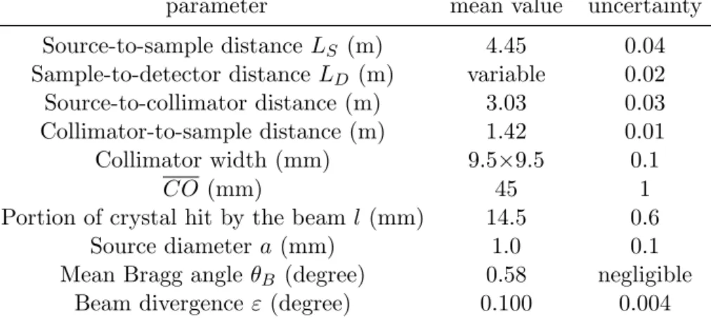
Table 2.6: Experimental and detector parameters an their uncertainty parameter mean value uncertainty Source-to-sample distance LS (m) 4.45 0.04
Sample-to-detector distance LD (m) variable 0.02
Source-to-collimator distance (m) 3.03 0.03 Collimator-to-sample distance (m) 1.42 0.01 Collimator width (mm) 9.5×9.5 0.1
CO (mm) 45 1 Portion of crystal hit by the beam l (mm) 14.5 0.6
Source diameter a (mm) 1.0 0.1 Mean Bragg angle θB (degree) 0.58 negligible
Beam divergence ε (degree) 0.100 0.004
Table 2.7: The detector: high-resolution and sensitive X-ray image intensifier coupled with a CCD camera
Number of pixels 512×512 Size of each pixel (mm) 0.35×0.35
Acquisition time few seconds
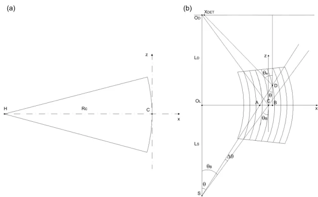
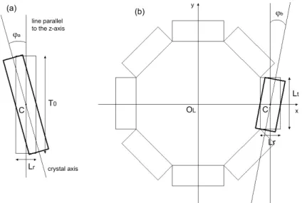
(ILL, Grenoble, France) [70, 71]. The diffractometer used a high-voltage and fine-focus X-ray tube designed for industrial radiography, the X-X-ray energy range being between 80 and 420 keV. The beam impinged onto the sample with an angle depending on the position at the entry face of the crystal. Thus, X-rays with different energies were diffracted towards the image point, which depended on the curvature of the crystal. A sketch of the experimental configuration is shown in Figs. 2.12.a and 2.12.b.
Diffraction of (111) planes was firstly analysed with the beam impinging on the crystal surface as in Fig. 2.12.a. Then, the crystal was rotated by 180◦ around the x axis (see
Fig. 2.12.b). The geometrical parameters are reported in Tab. 2.6, whereas the detector is described in Tab. 2.7. Considering the geometrical configuration, the energy range of diffracted beam turned out to be 160-227 keV.
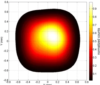
The crystal behaved as a cylindrical lens because the focusing effect occurred only in the scattering plane. Diffraction of a polychromatic and divergent beam produces a line on the detector [72]. The FWHM of the intensity profile, taken on a cross section perpendicular to the line, depends on several parameters. In the case of a perfect crystal and the sample-to-detector distance LD equal to source-to-sample distance LS, the width size depended only
on the X-ray source size and on the crystal thickness traversed by the beam. Conversely, a curved crystal can concentrate the diffracted X-rays at either smaller or larger distance.
Figure 2.12: Schematic representation of the experiment with a divergent polychromatic X-ray beam and the bent crystal with the QM curvature in Laue symmetric geometry. Depending on the sign of RP, the image distance increases (a) or decreases (b). (c) FWHM
of diffraction profile plotted as a function of sample-to-detector distance LD. Blue filled
circles plot the measured width related to (a) and red empty circles plot the measured width related to (b). Dashed lines enclose the range of the theoretical width calculated using Eq. 2.6 and considering the uncertainty over parameters. (d) Diffraction profile with detector in position P2 (LD = 3.45 m). Blue filled circles refer to (a), red empty circles refer
Indeed, under the small-angle approximation, it is possible to obtain 1 Li = 1 LS + 2 RP (2.5) where Li is the image distance of a bent crystal with primary radius of curvature equal to
Rp. The plate divides the space into a convex and a concave region1. We set RP < 0 when
the incident beam comes from the part of plane topologically convex (Fig. 2.12.a), while RP > 0 in the opposite case (Fig. 2.12.b).
To evaluate the focusing capability of the sample, we recorded the FWHM of the diffract-ing profile on the detector, that is
F W HM = √ a2+ ( 2tθB+ 2LD t RQM +l 1 − LD Li )2 (2.6) where a is the source diameter, t the sample thickness traversed by the beam, l the size of the beam on the crystal surface and RQM the radius of curvature of the QM diffracting planes. In
this case RQM < 0 when the incident beam comes from the part of plane topologically convex
with respect to the QM diffracting planes (Fig. 2.12.a), while RQM > 0 in the opposite case
(Fig. 2.12.b). The term 2LDRQMt represents the contribution of quasi-mosaicity, which can
modify the FWHM of the spot but not the distance Li. If LD = LS it is possible to obtain
the formula described in [73, 74].
The image distance was Li = 5.77 m for Fig. 2.12.a and Li= 3.62 m for Fig. 2.12.b. In
order to verify the effect of the crystal curvature, the detector was positioned at 5 different points indicated with P 1, P 2, P 3, P 4, P 5 in Figs. 2.12.a and 2.12.b, while LS was kept
fixed. LD was increased by steps of 1.00 m, starting from 2.45 m for P 1 to 6.45 m for P 5. In
Fig. 2.12.c the width of the measured diffraction profiles were plotted as a function of LD,
in agreement with their theoretical expectations. Finally, Fig. 2.12.d shows the measured diffraction profiles with LD = 3.45 m (P 2).