Holey fiber mode-selective couplers
Gaetano Bellanca,1 Nicolas Riesen,2,3 Alexander Argyros,4 Sergio G. Leon-Saval,4 Richard Lwin,4 Alberto Parini,1 John D. Love,2 and Paolo Bassi5,*
1Department of Engineering, University of Ferrara, Italy
2Research School of Physics and Engineering (RSPE), The Australian National University, ACT 2601, Australia 3Institute for Photonics and Advanced Sensing (IPAS) and School of Physical Sciences, The University of Adelaide,
SA 5005, Australia
4Institute of Photonics and Optical Science (IPOS), School of Physics, The University of Sydney, NSW 2006,
Australia
5Department of Electrical, Electronic and Information Engineering, University of Bologna, Italy *[email protected]
Abstract: Directional mode coupling in an asymmetric holey fiber coupler
is demonstrated both numerically and experimentally for the first time. The holey fiber mode couplers have interesting spectral characteristics and are also found to exhibit increased dimensional tolerances. Following a design based on numerical investigations, a dual-core polymer holey fiber coupler for LP01 and LP11 mode multiplexing was fabricated via a drilling and
drawing technique. The measurements are compared with the simulation results.
©2015 Optical Society of America
OCIS codes: (000.4430) Numerical approximation and analysis; (060.1810) Buffers, couplers,
routers, switches, and multiplexers; (060.4005) Microstructured fibers; (060.4230) Multiplexing; (060.5295) Photonic crystal fibers; (230.1150) All-optical devices.
References and links
1. R. Essiambre, G. Kramer, P. J. Winzer, G. J. Foschini, and B. Goebel, “Capacity limits of optical fiber networks,” J. Lightwave Technol. 28(4), 662–701 (2010).
2. J. D. Love and N. Riesen, “Single-, few-, and multimode Y-junctions,” J. Lightwave Technol. 30(3), 304–309 (2012).
3. J. B. Driscoll, R. R. Grote, B. Souhan, J. I. Dadap, M. Lu, and R. M. Osgood, Jr., “Asymmetric Y junctions in silicon waveguides for on-chip mode-division multiplexing,” Opt. Lett. 38(11), 1854–1856 (2013).
4. N. Riesen, J. D. Love, and J. W. Arkwright, “Few-mode elliptical-core fiber data transmission,” IEEE Photon. Technol. Lett. 24(5), 344–346 (2012).
5. S. G. Leon-Saval, N. K. Fontaine, J. R. Salazar-Gil, B. Ercan, R. Ryf, and J. Bland-Hawthorn, “Mode-selective photonic lanterns for space-division multiplexing,” Opt. Express 22(1), 1036–1044 (2014).
6. S. Yerolatsitis, I. Gris-Sánchez, and T. A. Birks, “Adiabatically-tapered fiber mode multiplexers,” Opt. Express
22(1), 608–617 (2014).
7. S. Gross, N. Riesen, J. D. Love, and M. J. Withford, “Three-dimensional ultra-broadband integrated tapered mode multiplexers,” Laser Photonics Rev. 8(5), L81–L85 (2014).
8. N. Riesen and J. D. Love, “Tapered velocity mode-selective couplers,” J. Lightwave Technol. 31(13), 2163– 2169 (2013).
9. N. Riesen, S. Gross, J. D. Love, and M. J. Withford, “Femtosecond direct-written integrated mode couplers,” Opt. Express 22(24), 29855–29861 (2014).
10. W. V. Sorin, B. Y. Kim, and H. J. Shaw, “Highly selective evanescent modal filter for two-mode optical fibers,” Opt. Lett. 11(9), 581–583 (1986).
11. S. H. Chang, H. S. Chung, N. K. Fontaine, R. Ryf, K. J. Park, K. Kim, J. C. Lee, J. H. Lee, B. Y. Kim, and Y. K. Kim, “Mode division multiplexed optical transmission enabled by all-fiber mode multiplexer,” Opt. Express
22(12), 14229–14236 (2014).
12. N. Hanzawa, K. Saitoh, T. Sakamoto, T. Matsui, K. Tsujikawa, M. Koshiba, and F. Yamamoto, “Two-mode PLC-based mode multi/demultiplexer for mode and wavelength division multiplexed transmission,” Opt. Express 21(22), 25752–25760 (2013).
13. N. Riesen, J. D. Love, and J. W. Arkwright, “Few-core spatial-mode multiplexers/demultiplexers based on evanescent coupling,” IEEE Photon. Technol. Lett. 25(14), 1324–1327 (2013).
14. J. D. Love and N. Riesen, “Mode-selective couplers for few-mode optical fiber networks,” Opt. Lett. 37(19), 3990–3992 (2012).
16. Z. Wang, G. Kai, Y. Liu, J. Liu, C. Zhang, T. Sun, C. Wang, W. Zhang, S. Yuan, and X. Dong, “Coupling and decoupling of dual-core photonic bandgap fibers,” Opt. Lett. 30(19), 2542–2544 (2005).
17. K. Saitoh, Y. Sato, and M. Koshiba, “Coupling characteristics of dual-core photonic crystal fiber couplers,” Opt. Express 11(24), 3188–3195 (2003).
18. J. Laegsgaard, O. Bang, and A. Bjarklev, “Photonic crystal fiber design for broadband directional coupling,” Opt. Lett. 29(21), 2473–2475 (2004).
19. K. Saitoh, Y. Sato, and M. Koshiba, “Polarization splitter in three-core photonic crystal fibers,” Opt. Express
12(17), 3940–3946 (2004).
20. L. Zhang and C. Yang, “Polarization splitter based on photonic crystal fibers,” Opt. Express 11(9), 1015–1020 (2003).
21. B. H. Lee, J. B. Eom, J. Kim, D. S. Moon, U.-C. Paek, and G. H. Yang, “Photonic crystal fiber coupler,” Opt. Lett. 27(10), 812–814 (2002).
22. B. J. Mangan, J. C. Knight, T. A. Birks, P. St. J. Russell, and A. H. Greenaway, “Experimental study of dual-core photonic crystal fibre,” Electron. Lett. 36(16), 1358–1359 (2000).
23. Comsol Multiphysics, http://www.comsol.com
24. F. Fogli, L. Saccomandi, P. Bassi, G. Bellanca, and S. Trillo, “Full vectorial BPM modeling of index-guiding photonic crystal fibers and couplers,” Opt. Express 10(1), 54–59 (2002).
25. J. Laegsgaard, “Directional coupling in twin-core photonic bandgap fibers,” Opt. Lett. 30(24), 3281–3283 (2005).
26. H. Arao, O. Shimakawa, M. Harumoto, T. Sano, and A. Inoue, “Compact multi-core fiber fan-in/out using GRIN lens and microlens array,” in Proc. OECC/ACOFT, p.42–43 (2014).
27. Y. Sasaki, H. Uemura, K. Takenaga, S. Nishimoto, T. Uematsu, K. Omichi, R. Goto, S. Matsuo, and K. Saitoh, “Multicore fiber-based mode multiplexer/demultiplexer,” Proc. SPIE 9389, 938905 (2015).
28. K. Watanabe, T. Saito, and M. Shiino, “Development of fiber bundle type fan-out for 19-core multicore fiber,” in
Proc. OECC/ACOFT, p.44–45 (2014).
29. D. G. Lancaster, S. Gross, H. Ebendorff-Heidepriem, K. Kuan, T. M. Monro, M. Ams, A. Fuerbach, and M. J. Withford, “Fifty percent internal slope efficiency femtosecond direct-written Tm³⁺:ZBLAN waveguide laser,” Opt. Lett. 36(9), 1587–1589 (2011).
30. E. Bricchi, B. G. Klappauf, and P. G. Kazansky, “Form birefringence and negative index change created by femtosecond direct writing in transparent materials,” Opt. Lett. 29(1), 119–121 (2004).
1. Introduction
Mode-division multiplexing appears to be one of the final frontiers for increasing optical fiber capacity beyond the soon-to-be reached capacity limits of single-mode fiber [1]. Although simple in concept, mode-division multiplexing carries some considerable technological challenges, such as the independent excitation and detection of the actual spatial modes of the few or multimode fibers used. Several potential solutions to this problem have been proposed: simple and practical light-processing waveguide devices such as asymmetric Y-junctions [2– 4], dissimilar-core photonic lanterns [5, 6], tapered velocity mode couplers [7, 8] and mode-selective couplers [9–14]. In this paper we consider mode-mode-selective couplers, which involve directional coupling between a higher-order mode of one fiber core and the fundamental mode of another closely-positioned core, or vice versa [14]. The mode-selective functionality is achieved through the matching of the modal propagation constants by, for instance, using different diameter cores. As with standard directional couplers, these mode-selective variants are in essence interference-based devices. Mode couplers are hence sensitive to the operating wavelength, especially since both the coupling length and the propagation constant matching are wavelength-dependent [14]. This presents an issue if such devices were to be used for wideband mode-division multiplexing.
This paper suggests that, by exploiting the unusual spectral characteristics of holey fibers, broadband mode-selective couplers can be designed and fabricated. In this paper, theoretical and preliminary experimental results of mode-selective coupling in a holey fiber based device are reported for the first time, with the results showing that coupling can also be selective with respect to polarization, a feature that increases the versatility of the device.
2. Mode-selective coupler design
Holey fibers are index-guiding photonic crystal fibers (PCF) that have a cladding consisting of a series of air-holes extending the length of the fiber [15]. Guidance is assured by total internal reflection coming from the smaller volume average refractive index of the cladding
compared to that of the core [16]. Directional coupling in symmetric dual-core devices has been investigated previously both theoretically [17–20] and experimentally [21, 22], with applications including polarization splitting [19, 20] and super-broadband directional coupling [18]. The asymmetric mode-selective coupler presented in this paper shares similar broadband characteristics, whilst permitting directional coupling between different modes.
In the dual-core holey fiber coupler proposed here, each of the two cores is defined by concentric rings of air holes which provide sufficiently strong guidance to ensure minimal light leakage over the device length. Coupling occurs between the fundamental LP01 mode of
the smaller core and the degenerate (i.e. propagation constant matched) second anti-symmetric LP11a mode of the larger core. The degeneracy is achieved by careful choice of
core diameters. The design process for the dual-core coupler involved a numerical analysis of different geometries using a Finite Element Method (FEM) [23]. The material assumed in the design is polymethylmethacrylate (PMMA), which is a low-cost polymer that is transparent in the visible up to 850 nm [15]. In the infrared the transparency of the polymer is reduced by C-H bond absorption [15]. Polymer was chosen instead of silica to simplify fabrication of the fiber coupler by permitting the use of a drilling and drawing technique [15], instead of using e.g. relatively complicated stacked silica preforms. The present work represents a proof of concept for mode coupling in holey fiber devices, although for telecommunications applications a silica variant would be preferred. The use of silica instead of polymer would also mitigate issues relating to cleaving and splicing. For the present case of a polymer device, to both minimize losses and facilitate the experimental demonstration or characterization of the coupler, the nominal wavelength was set at λ ~633 nm. The holes used in the design had a radius of 1.1 μm to ensure compatibility with the available fabrication method.
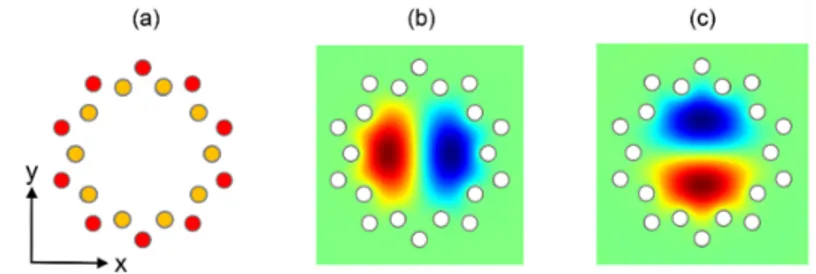
Fig. 1. (a) Geometry of the large fiber core. Field patterns of the (b) Ex/Ey components of the LP11a mode and (c) Ex/Ey components of the LP11b mode.
The cores of the dual-core coupler were initially studied in isolation. First, holey fiber cores with just a single ring of holes were considered (e.g. yellow holes, Fig. 1). The effective index of the LP11 mode of a large fiber core (i.e. 10 hole ring, radius 10 μm) and that of the
LP01 mode of a smaller fiber core (i.e. 7 hole ring, radius 6.5 μm) were closely matched (neff
~1.4884). Unfortunately, these fiber cores were highly lossy (20 dB/m and 17 dB/m respectively). With the addition of a second outer ring of holes (e.g. red holes, Fig. 1), the effective indices of the modes of the two fiber cores remained almost unchanged, although the losses decreased dramatically to acceptable values well below material absorption (0.086 and 0.012 dB/m, compared to a material loss exceeding 0.15 dB/m [15]).
The larger fiber core also supports the LP01 mode with neff = 1.4888, although the index
mismatch with the LP01 mode of the smaller core (neff = 1.4884) ensures negligible coupling
between these modes when the two cores are brought together. Among the possible polarizations of the LP11 mode of the large fiber core (see Fig. 1) that are permitted by
rotational symmetry, we consider those with electric field components (Ex or Ey) showing an
intensity distribution with two lobes and a vertical (LP11a) or a horizontal (LP11b) node line.
The former, shown in Fig. 1(b), corresponds to fields having Perfect Magnetic Conductor Symmetry (PMCS) for the Ex and Perfect Electric Conductor Symmetry (PECS) for the Ey
components with respect to the horizontal x axis. The latter, shown in Fig. 1(c), corresponds to Ex (PECS) and Ey (PMCS) field symmetry with respect to the same axis.
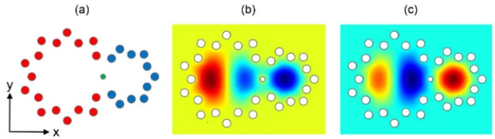
As suggested, the coupler is obtained by positioning the two fiber cores side by side, as shown in Fig. 2(a). In this figure, the red holes define the large fiber core, whereas the blue holes define the small core. As shown later, coupling between the two cores can be controlled by varying the radius of the central hole shared by the two cores (i.e. the green hole in Fig. 2(a)). The radius of this coupling hole was initially chosen at 0.75 μm.
For the coupler geometry we consider the quasi degenerate supermodes that exist. The two supermodes with largest and smallest values of the effective index neff have Ex components
with field distributions shown in Fig. 2, exhibiting PMCS along the x axis. Those with intermediate values of neff have Ey components exhibiting PECS. Their Ey field distributions
have the same overall pattern as the other pair of supermodes. Each set of supermodes interfere, hence allowing for power exchange between the respective cores.
Fig. 2. (a) Geometry of the dual-core coupler. (b)-(c) Distribution of the Ex/Ey field components of the two supermodes with PMCS/PECS along the horizontal x axis.
In this paper we limit our attention to coupling between the LP01 mode of the small fiber
core and a single LP11 mode polarization of the large core. The underlying principles of mode
coupling in holey fiber devices are however extendable to other pairs of modes.
3. Mode-selective behavior
A preliminary study of the dependence of coupling performance on device geometry (i.e. radii of fiber cores and holes) has been carried out using the field distributions and the relevant FEM-calculated propagation constants. In particular, coupling lengths have been determined via the classical equation: Lc = λ / Δneff, with λ being the free-space operating wavelength and
Δneff the difference in effective indices of the two supermodes with the same symmetry.
Starting with the geometry of Fig. 2(a), the cross-section of the structure was scaled, to simulate e.g. imperfect fiber drawing, and therefore provide insight into the fabrication tolerances. Two scale factors were introduced to independently alter the structure size: the first referring to both the fiber cores and hole radii (Structure Scale Factor, SSF), and the second changing only the radius of the coupling hole (Coupling Hole Scale Factor, CHSF). Indeed, it is known that fiber drawing can affect holes of different sizes in different ways.
The influence of the CHSF on the coupling lengths for different values of SSF is shown in Fig. 3. Continuous/dashed lines correspond to supermodes with larger values of the Ex/Ey
components, respectively. Red/blue/green/black lines refer to SSF = 1/0.85/0.75/0.7. For small values of CHSF, for which the coupling hole size is smaller than that of the other fiber holes (i.e. left part of figure), reducing the overall structure size decreases the coupling length Lc with negligible polarization dependence. For larger values of CHSF, corresponding to
structures in which the coupling hole size becomes comparable to or greater than the fiber holes (i.e. right part of figure), the coupling becomes both less effective (Lc increases) as well
Fig. 3. FEM-calculated coupling length as a function of Coupling Hole Size Factor (CHSF) for a Structure Scale Factor, SSF = 1.0 (red), 0.85 (blue), 0.75 (green), 0.7 (black). Solid and dashed lines refer to Ex and Ey polarizations, respectively.
Fig. 4. Values of supermode effective indices neff as a function of the Coupling Hole Size
Factor (CHSF) for Structure Scale Factor, SSF = 0.85. Blue and red lines refer to Ex and Ey, respectively.
Analyzing in more detail the physics of the device, the polarization dependence of Lc was
found to result from different behavior of the effective indices of the supermodes with changes in the CHSF parameter. An example of this is shown in Fig. 4, where the values of the effective indices are reported for SSF = 0.85. Here the two smaller effective index neff
values of the two supermodes do not vary significantly, whereas the larger supermode effective indices do change with respect to the radius of the coupling hole.
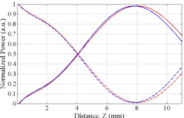
Coupling between the two fiber cores was also investigated through a Finite Difference full vectorial Beam Propagation Method (BPM) approach [24]. Figure 5 shows the longitudinal power distribution for different excitations of the large core of the original coupler structure. As predicted by FEM, coupling does not exist between the two polarizations of the LP11b mode (Ex or Ey with horizontal node line, inset (ii) in Fig. 5) in the
large core and the LP01 mode of the smaller core. On the contrary, efficient coupling is
observed when the LP11a mode is launched (either Ex or Ey with vertical node line, see inset
(iii) in Fig. 5). The absence of coupling with the two polarizations of the LP11b mode is
Fig. 5. Plot of the power in each fiber core for different excitations of the large core. Launching the two polarizations (Ex, Ey) of the LP01 mode (inset i) or those of the LP11b mode (inset ii) one gets nearly identical (i.e. superimposed) curves. In particular, the green and magenta curves (a,b) refer to the excitation of the LP11b mode polarizations. The blue and red curves (c) refer to the excitation of the two polarizations of the LP11a mode (inset iii). Solid lines refer to power evaluated in the larger fiber core, whereas dashed lines refer to power in the smaller core.
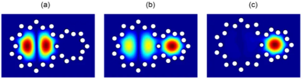
The intensity distributions in three different sections of the coupler are shown in Fig. 6: the start, the half coupling length (Lc/2) and the full coupling length (Lc) when the Ex field of
the LP11a mode is excited in the large core of the coupler. Nearly identical intensity
distributions, but with slightly different values of Lc, are obtained when the Ey field of the
same mode is launched. BPM predicts values of Lc of about 27-28 mm, which are in good
agreement with FEM results (see Fig. 3).
Fig. 6. Field intensities calculated at Z = 0, Lc/2, and Lc when the Ex polarization of the LP11a mode of the large fiber core is launched.
Figure 7 shows the coupling for the LP11a polarizations with a reduced CHSF. The
coupling lengths decrease, but remain nearly identical for the two different polarizations, as expected from the FEM calculations. The slight difference in the values of Lc evaluated by
FD-BPM compared with the FEM values may be due to the staircase approximation of the geometry used in BPM, which does not allow for precise modeling of the smaller coupling hole.
An interesting feature of the proposed device is its reduced wavelength-dependence compared to that of an asymmetric coupler realized using standard step-index fiber cores. This is demonstrated using BPM simulations in Fig. 8, where the wavelength-dependence of the holey fiber coupler is compared with that of an analogous step-index coupler. Here, the core diameters of the two couplers are nearly identical, with only slight differences to ensure both devices are phase-matched.
Fig. 7. Plot of the power in each fiber core for different excitations of the large core. Settings are identical to those of Fig. 5 except that CHSF = 0.4. As before, the blue and red curves refer to the power evolutions in the two cores when the two polarizations of the LP11a mode are launched. Dashed lines refer to power evaluated in the larger fiber core, whereas solid lines refer to power in the smaller core.
Fig. 8. Wavelength-dependence of coupling from the LP01 mode excited in the small fiber core to the LP11a mode of the large core of the holey fiber coupler. Also shown is the spectral response of an analogous step-index fiber mode coupler. Results obtained using numerical BPM simulations.
The considerably lower wavelength-dependence of the holey fiber coupler is attributed to the strong dependence of the effective refractive index of the polymer-air cladding on wavelength. The further the field extends outside the core, the higher the effective index of the cladding. For this reason, the phase-matching condition is less sensitive to the specific wavelength compared with a standard step-index mode coupler. The fabrication tolerances are also improved for similar reasons. The holey fiber coupler’s bandwidth is shown to span almost the entire visible spectrum. It is believed that by incorporating an index depression in the cores, even greater bandwidth could be achieved for the holey fiber mode coupler, because of wavelength-flattening of the coupling length [18]. The broadband nature of the holey fiber coupler demonstrated in this paper, is also likely to apply to couplers involving modes of higher order, although this would require further investigation.
Note also that similar broadband performance is expected for silica-based holey fiber couplers which, unlike the polymer devices presented here, would be suitable for use within the telecommunications bands. The low wavelength-dependence would be of particular benefit if such a device were to be used for combined mode- and wavelength-division
4. Preliminary experimental results
A prototype of the device was fabricated by drilling the designed hole pattern into a solid PMMA cylinder to form the primary preform. This was followed by drawing it into a cane, sleeving it with polycarbonate, and further drawing to the final fiber diameter of approximately 190 μm. The length of fiber used for the device was 2.0 ± 0.2 cm corresponding to approximately Lc/2 with SSF ~0.9 in Fig. 3. The propagation losses over the
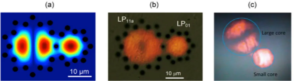
short length of the device were negligible. The hole diameters were measured at approximately 2 µm, with the coupling hole at around 1.2 µm corresponding to a SSF and CHSF of 0.9 and 0.8, respectively. Indicative values for the smaller and larger core diameters were 13 µm and 22 µm, respectively. The near-field output of the dual-core coupler when exciting the fundamental mode in the small core was then measured. Excellent agreement exists in the 3 dB coupling section between the calculated (Fig. 9(a)) and measured (Figs. 9(b) and 9(c)) field intensities. Figure 9(b) shows the measured near-field distribution when the small core of the coupler is excited using a supercontinuum source for an approximately 600-700 nm bandwidth. Figure 9(c) shows the measured output when a 10 nm bandpass filter centered at 600 nm is added.
Fig. 9. (a) BPM-calculated intensity pattern for the 3 dB coupling cross section. Coupler output measured in the near-field after launching into the small core using a supercontinuum source for an approximately 600-700 nm bandwidth without (b) and with (c) a 10 nm bandpass filter centered at 600 nm.
As suggested, the close proximity of the cores in the design is necessary to ensure strong coupling. This however complicates the launch and detection of the light in the two cores. In the experiment, to ensure that only the fundamental mode in the smaller core was being excited, launching was achieved by direct butt-coupling to a single-mode silica fiber, either a PCF or a step index fiber, with a core diameter of 5 µm or smaller. The light in the two cores could however be excited/separated much more effectively using one of several practical approaches involving either tapering, or fan-in/fan-out configurations similar to those described in [26–28]. As mentioned, the dual-core device presented in this paper allows coupling to only the LP11a mode and no coupling occurs to the orthogonal LP11b mode. Using
the present fabrication technique it may not be practical to multiplex such orthogonal mode pairs using e.g. a linear cascade of dual-core couplers or a multi-core coupler configuration [14]. In terms of scaling the device to additional modes, more practical structures might be realized using e.g. the femtosecond-laser direct write technique in which ‘holes’ or index depressions could be inscribed into bulk glass via laser-induced negative index changes [29, 30]. In such an approach a linear cascade of two- or three-core couplers with arbitrary angular offsets could be inscribed into the glass, with an appropriate fan-in fan-out configuration to separate out the individual cores at either end of the device.
At this point it is also worth noting that there may exist the potential to design and fabricate photonic bandgap variants of the dual-core coupler demonstrated here. This could be realized by e.g. filling the air-holes with high-index rods. In this configuration the cladding states in the high-index regions are likely to mediate interaction between the relevant modes
in the cores via off-resonant coupling [17]. Therefore even stronger coupling would be expected allowing for a greater separation of fiber cores in the interaction region.
5. Conclusion
This paper has reported the first realization of a mode-selective coupler based on holey fiber technology. Preliminary experimental results are in agreement with theoretical and numerical predictions. Variants of the proposed device have potential to be used for mux/demux operations in mode-multiplexed networks for increasing optical fiber capacity. Its features include mode and polarization selectivity, and low wavelength-dependence making it a promising solution for further investigation.
Acknowledgments
N. Riesen acknowledges the support of an Australian Research Council Georgina Sweet Laureate Fellowship awarded to T. M. Monro, FL130100044. This work was performed in part at the Optofab node of the Australian National Fabrication Facility (ANFF) using Commonwealth and NSW State Government funding.