1
University of Salerno
Department of Chemistry and Biology
PhD in
SCIENCE AND TECHNOLOGY FOR
CHEMICAL,PHARMACEUTICAL AND FOOD INDUSTRY”
XII CYCLE - Chemistry Curriculum
2013/2014
New Chemical Topologies
Based on Calixarene Threading
2
Supervisors
Prof. Placido Neri
University of Salerno
Prof. Yoram Cohen
University of Tel Aviv
Counter Supervisor
Prof. Francesco De Riccardis
University of Salerno
Coordinator
Prof. Gaetano GuerraUniversity of Salerno
University of Salerno
Department of Chemistry and Biology
Ph.D in
SCIENCE AND TECHNOLOGY FOR CHEMICAL, PHARMACEUTICAL, AND FOOD INDUSTRY”
XII CYCLE - Chemistry Curriculum 2011-2014
Ph.D. Thesis
New Chemical Topologies Based on Calixarene Threading
Roberta Ciao
3
CHAPTER I
1. Supramolecular Topology Outline 15
1.1 Supramolecular Topology. An informal discussion 15
1.2 DNA topological isomerism 22
1.3 Supramolecular topologies: from paper to laboratory 24
1.3.1 Catenanes and Rotaxanes 24
1.3.2 Molecular knots 34
1.4 Topological and functional complexity 43
1.4.1 Rotaxanes and Catenanes as supramolecular devices. 43
1.4.2 Rotaxanes and catenanes innanotechnology 51
CHAPTER II 2.1 Complex Topologies based on Calixarenes 56
2.2 Supramolecular Properties of Calix[n]arenes 60
2.3 Through-the-Annulus Threading of Large Calixarenes Induced by Very Loose Alkylammonium Ion Pairs 62
CHAPTER III 3.1 Goal of the research 71
CHAPTER IV 4.1 Introduction 76 4.2 Synthesis of double-calix[6]arene Derivative 12. 79 4.3 Synthesis of double-threaded[2]pseudorotaxane 14,16 82 4.3.1 Threading of double-calix[6]arene 12 with di-n- pentylammonium axle 2+ 83 4.3.2 Directional threading of double-calix[6]arene 12 with nonsymmetrical n- butylbenzylammonium axle 89 4.4 Synthesis of Double-Calix[6]arene Derivative 21 94 4.5 Synthesis of double-threaded[2]pseudorotaxane 22, 23. 97
4.5.1 Threading of double-calix[6]arene 21 with di-n- pentylammonium axle 2+ 97 4.5.2 Directional threading of double-calix[6]arene 21 with nonsymmetrical n- butylbenzylammonium axle 3+ 100 4.5.3 Threading of double-calix[6]arene 21 with di- benzylammonium axle 4+ 103
4.6 Conclusion 104
4.7 Experimental section 106
4.7.1 Synthesis and characterization of double-calixarene 12. 108
4
4.7.2 Preparation of singly-threaded pseudo[2]rotaxanes
13,15 116
4.7.3 Preparation of doubly threaded pseudo[3]rotaxanes 14,16 119 4.7.4 Synthesis and characterization of double-calixarene 21 122
4.7.5 Preparation of singly-threaded pseudo[2]rotaxanes 22
24, 26 130
4.7.6 Preparation of doubly-threaded pseudo[3]rotaxanes
23, 25, 27 134
4.7.7 Determination of Kass values of (2+)212 and (3+)212
complexes by quantitative 1H NMR analysis 139
CHAPTER V
5.1 Introduction 141
5.2 Stereo-programmed synthesis of (T,T)-handucff-[2]rotaxane 146
5.2.1 Stereo-programmed formation of an (T,T)-handucuff-
pseudo[2]rotaxane (292+) 146
5.2.2 Stereo-programmed synthesis of an (T,T)-handcuff-
[2]rotaxane (322+) 153
5.3 Stereo-programmed formation of (H,H)-handucuff-[2]rotaxane 158
5.3.1 Stereo-programmed formation of an (H,H)-handucuff-
pseudo[2]rotaxane (342+) 158
5.3.2 Stereo-programmed synthesis of an (H,H)-handucuff-
[2]rotaxane (372+) 161
5.4 Stereo-programmed formation of (H,T)-handucuff-[2]rotaxane 167
5.4.1 Stereo-programmed formation of an (H,T)-handucuff-
pseudo[2]rotaxane (392+) 167
5.4.2 Stereo-programmed synthesis of an (H,T)-handucuff-
[2]rotaxane (422+) 169
5.5 Experimental section 176
5.5.1 Preparation of handcuff pseudo[2]rotaxane (T,T)-292+ 177 5.5.2. Preparation of handcuff pseudo[2]rotaxane (T,T)-312+ 179
5.5.3. Synthesis of handcuff [2]rotaxane (T,T)-322+ 180
5.5.4 Simulated Annealing Experiments on handcuff
pseudo[2]rotaxane (T,T)-312+ 185
5.5.5 Simulated Annealing Experiments on handcuff
[2]rotaxane (T,T)-322+ 185
5.5.6 Preparation of handcuff pseudo[2]rotaxane (H,H)-342+ 186 5.5.7 Preparation of handcuff pseudo[2]rotaxane (H,H)-362+ 188 5.5.8 Synthesis of handcuff [2]rotaxane (H,H)-372+ 189
5.5.9 Preparation of handcuff pseudo[2]rotaxane (H,T)-392+ 193 5.5.10 Synthesis and characterization of thread 402+ and its
precursors 194
5.5.11 Preparation of handcuff pseudo[2]rotaxane (H,T)-412+ 212
5
5.6 Conclusion 216 CHAPTER VI 6.1 Introduction 218 6.2 Synthesis of triple-tert-butylated-calix[6]arene (57) 220 6.3 Synthesis of triple-threaded[4]pseudorotaxane 2226.3.1 Threading of triple-calix[6]arene 57 with di-n-
pentylammonium axle 2+ 224
6.3.2 Threading of triple-calix[6]arene 57 with di-
benzylammonium axle 4+ 226
6.3.3
Directional threading of triple-calix[6]arene 57 withnonsymmetrical n-butylbenzylammonium axle 3+ 228
6.4 Experimental section 232
6.4.1 Synthesis of triple tert-butylated-calix[6]arene 57 233 6.4.2 Preparation of singly-threaded pseudo[2]rotaxanes 58+,
61+ and 64+ 235
6.4.3 Preparation of triply-threaded pseudo[4]rotaxanes 603+,
633+ and 663+ 240
6.5 Conclusion 245
CHAPTER VII
6
FIGURE LISTS
Figure 1. Classical topological transformation: a donut that becomes a
cup………..…
Figure 2. Some simple objects for the consideration of Euclidean
geometry………..
Figure 3. Topologically equivalent constructions... Figure 4. Two topologically distinct closed curve structures Figure 5. Structure and graph of a fungicide
Figure 6. On the left a planar graph, on the right a non-planar graph…..45 Figure 7. (a ) A right and left handed trefoil knot; (b) an achiral figure-of-
eight knot………
Figure 8. Topoisomerase General mechanism………
Figure 9. Micrograph of DNA topological isomers by the action of DNA
topoisomerase………..
Figure 10. A pseudorotaxane: common precursor to catenane and
rotaxane……….
Figure 11. Pseudorotaxane Rotaxane………...
Figure12. A catenane structure and its cartoon
representation……….
Figure 13. Nomenclature pseudorotaxanes rotaxanes and catenanes Figure 14. Wasserman [2]catenane
Figure 15. Schill and Lüttingraus [2]catenane by template synthesis
Figure 16. Schematic representation of the synthesis of a catenane by the
metal template effect..
Figure 17. A supramolecular self-assembly process of [2]-catenane. Figure 18. Rotaxane obtain by threading e stoppering.
Figure 19. Cartoon representation of the clipping strategy for the
synthesis of a rotaxane...
Figure 20. Cartoon representation of a slipping strategy for the synthesis of
a rotaxane
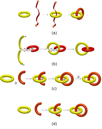
Figure 21. Cartoon representation of (a) a statistical, (b) a directed, (c) a
metal templated synthesis and (d) electrostatic interaction or H- bonding templated synthesis for a catenane.
Figure 22. (a) Lactoferrin structure (b) acid ascorbic structure
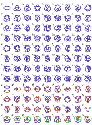
Figure 23. A schematic tabulation of simple knots and links, accompanied
by their trivial names and descriptors using the Alexander-Briggs notation.
Figure 24. Trefoil knot rapresentation
Figure 25. A visualization of the inherent topological chirality of Trefoil
Knots
Figure 26. Knot Sauvage Synthesis.
Figure 27 Sauvage Trefoil Knot Synthesized via the metathesis.
Figure 28. Examples of decorative Solomon Link (on the left) on an Italian
7
Figure 29. Schematic rapresentation of Borromeam rings and molecular
equivalents of its constituents.
Figure 30. Stoddart olympiadane
Figure 31. Ball-and-stick representation of the solid-state structure of a
suit[2]ane
Figure 32. A molecular clamp by light activated, structure (on the left) and
cartoon representation(on the right).
Figure 33. Molecular Shuttle driven by chemical impulses Figure 34. A four-stroke engine based on rotaxane
Figure 35. Diagram of a pH dependent molecular shuttle.
Figure 36. Redox controlled ring rotation in a catenane containing a non-
symmetric ring
Figure 37. The molecular elevator of Stoddart and Balzani in a graphical
representation.
Figure 38. Structure of the bistable [2]rotaxane used in the crossbar
memory and SEMs of the nanowire crossbar memory
Figure 39. Molecular junction constituted by a layer of bistable [2]
catenanes.
Figure 40. Schematic representation of a molecular carrier and bistable
[2]rotaxane structure
Figure 41. AFM image on the writing on a rotaxane film Figure 42. Calix crater and p-terz-butilcalix[4]arene structure Figure 43. The phenol-derived calixarene family
Figure 44. (a) Crown ethers, cucurbiturils and cyclodexstrines; (b)
Structure of larger calix[n]arene (n = 6, 7 e 8)
Figure 45. Threading of calix[6]arene derivative. Figure 46. Threading of calix[6]arene derivate.
Figure 47. Through-the-Annulus Threading of Calixarenes. Induced by Very
Loose Alkylammonium Ion Pairs
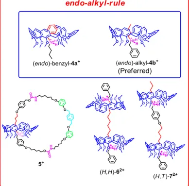
Figure 48. The endo alkyl preference
Figure 49. [2]rotaxane synthesis and its unprecedented inversion of the
wheel orientation
Figure 50. Through-the-annulus threading of nonsymmetrical alkylbenzyl ammonium cations by hexaalkoxycalix[6]arene
Figure 51. The three stereoisomeric [3]rotaxane structures named a.Tail to
Tail, b. Head to head, and c.Head to Tail.
Figure 52. Calix[6]arene-based catenane
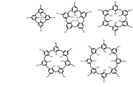
Figure 53. Double-calix[6]arene and tris-calix[6]arene structures Figure 54. Double-calixarene-based handcuff-rotaxane
Figure 55. Three stereoisomeric handcuff-pseudo[3]rotaxane structures Figure 56. Double-threaded[2]catenane topologies
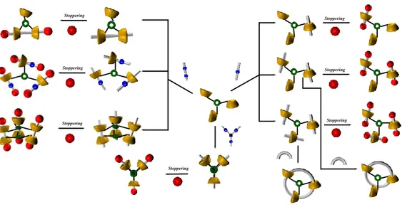
Figure 57. The variety of topological isomers obtainable from a tris-
calixarene host.
Figure 58. The endo-alkyl rule
8
examples of handcuff-derived architecturesFigure 60. Stereoisomeric oriented handcuff pseudo-[2]rotaxanes Figure 61. 1H NMR spectrum of double-calixarene derivative 12
Figure 62. Linear mono-ammonium systems, double‒calixarene host Figure 63. Schematic representation of directional threading of 12 with the
n-butylbenzylammonium axle 3+
Figure 64. 1H NMR of: a) 12 (aa x10-3 M); b)12 and 0.5 equiv of 2+; c)12 and 1 equiv of 2+; d)12 and 2 equiv of 2+; e)12 and 3 equiv of 2+; f) significant portion of the ESI(+) mass spectrum of a mixture of 12 and 1 equiv of 2+.
Figure 65. 2D COSY spectrum of the 1:1 mixture of 12 and 2+∙TFPB−.
Figure 66. HSQC spectrum of an equimolar solution of 2+ and 12.
Figure 67. DFT calculation.
Figure 68. Schematic representation of Directional threading of 12 with the
n-butylbenzylammonium axle 3+.
Figure 69. The “endo-alkyl rule” and related examples of oriented
interpenetrated architectures.
Figure 70. Possible double-threaded pseudo[2]rotaxane stereoisomers by
directional threading of 12 with the n-butylbenzylammonium axle 3+.
Figure 71. 1H NMR of: a)12 (aa x10-3 M); b)12 and 0.25 equiv of 3+; c)12 and 0.5 equiv of 3+; d)12 and 0.75 equiv of 3+; e)12 and 1.0 equiv of 3+; f) 12 and 2.0 equiv of 3+; g) ESI(+) mass spectrum of a mixture 1:1 of 12 and 3+.
Figure 72. Energy-minimized structures of the (3+)212 complex (B3LYP
DFT calculation
Figure 73. Energy-minimized structures of endo-alkyl/endo-alkyl (3+)212 (B3LYP DFT calculation using the 6-31G* basis set).
Figure 74. 1H NMR spectrum of double-calixarene derivative 21
Figure 75. Linear mono-ammonium systems, double-calixarene host
21
Figure 76. Schematic representation of directional threading of 21 with the
n-butylbenzylammonium axle 2+.
Figure 77. 1H NMR (400 MHz, 298 K, CDCl3) of: a) 21(aa x10-3 M); b) 21
and 1.0 equiv of 2+; c) 21 and 2.0 equiv of 2+; d) 21 and 5.0 equiv of 2+; significant portion of the ESI(+) mass spectrum of a mixture of 21 and 1.0 equiv of 2+.
Figure 78. Significant portions of the 2D COSY spectrum of the 1:2 mixture
of 21 and 2+∙TFPB−.
Figure 79. Schematic representation of Directional threading of 21 with the
n-butylbenzylammonium axle 3+.
Figure 80. Possible double-threaded pseudo[2]rotaxane stereoisomers by
directional threading of 21 with the n-butylbenzylammonium axle 3+.
9
and 2.0 equiv of 3+; d) 21 and 5.0 equiv of 3+;Figure 82. Significant portions of the 2D COSY spectrum of the 1:2 mixture
of 21 and 3+∙TFPB−.
Figure 83. Schematic representation of threading of 21 with the di-
benzylammonium axle 4+.
Figure 84. 1H NMR of: a) 21(aa x10-3 M); b) 21 and 0.5 equiv of 4+; c) 21
and 1.0 equiv of 4+; d) 21 and 2.0 equiv of 4+
Figure 85. Significant portions of the 2D COSY spectrum of the 1:2 mixture
of 21 and 4+∙TFPB−
Figure 86. 1H NMR spectrum of derivative 9.
Figure 87. 13C NMR spectrum of derivative 9
Figure 88. 1H NMR spectrum of derivative 10
Figure 89. 13C NMR spectrum of derivative 10
Figure 90. 1H NMR spectrum of derivative 11.
Figure 91. 13C NMR spectrum of derivative 11.
Figure 92. 1H NMR spectrum of derivative 12 .
Figure 93. 13C NMR spectrum of derivative 12.
Figure 94. ESI(+) MS spectrum of derivative 12.
Figure 95. 1H NMR spectrum of the 1:1 mixture of 12 and 2+∙TFPB−
Figure 96. 2D COSY spectrum of the 1:1mixture of 12 and 2+∙TFPB− Figure 97. 1H NMR spectrum of the 1:1 mixture of 12 and 3+∙TFPB−
Figure 98. 1H NMR spectrum of the 1:2 mixture of 12 and 2+∙TFPB−
Figure 99. 1H NMR spectrum of the 1:2 mixture of 12 and 3+∙TFPB−
Figure 100. Spectrum 1H NMR of derivative 18.
Figure 101. Spectrum 13C NMR of derivative 18.
Figure 102. Spectrum 1H NMR of derivative 19
Figure 103. Spectrum 13C NMR of derivative 19
Figure 104. Spectrum 1H NMR of derivative 20
Figure 105. Spectrum 13C NMR of derivative 20
Figure 106. Spectrum 1H NMR of derivative 21
Figure 107. Spectrum 13C NMR of derivative 21
Figure 108. ESI(+) MS spectrum of derivative 21.
Figure 109. 1H NMR spectrum of the 1:1 mixture of 21 and 2+∙TFPB−
Figure 110. 1H NMR spectrum of the 1:1 mixture of 21 and 3+∙TFPB−
Figure 111. 1H NMR spectrum of the 1:2 mixture of 21 and 3+∙TFPB−
Figure 112. 1H NMR spectrum of the 1:2 mixture of 21 and 4+∙TFPB−
Figure 113 Cartoon representations of handcuff-like systems
Figure 114. Stereo-programmed direct synthesis of calixarene-based
[2]rotaxanes
Figure 115. Handcuff-rotaxanes
Figure 116. Sequence stereoisomerism in handcuff-[2]rotaxane
Figure 117. 1H NMR spectra of: (a) 12, (b) an equimolar mixture of 12 and 282+∙ 2TFPB−, (c) an equimolar mixture of 12 and
302+∙ 2TFPB−
10
minimized structure (inset)Figure 119. Expansions of 2D COSY-45 spectrum of an equimolar mixture
of 12 and 282+∙ 2TFPB−
Figure 120. Lowest energy structure of three possible handcuff-
pseudo[2]rotaxane 312+ (from left to right: T,T; H,T and H,H)
Figure 121. (a-c) Snapshot from an MD simulation of (T,T)-handcuff-
pseudo[2]rotaxane 312+
Figure 122. ESI(+) mass spectrum of (T,T)-322+ and its AMBER energy- minimized structure (inset)
Figure 123.(a) 1H NMR spectrum of handcuff-[2]rotaxane (T,T)-322+
Figure 124. Lowest energy structure of the (T,T)-handcuff-
pseudo[2]rotaxane 312+
Figure 125. 1H NMR spectra of: (a) 12, (b) an equimolar mixture of 12 and 372+∙ 2TFPB−, (c) an equimolar mixture of 12 and 312+∙
2TFPB−
Figure 126. 2D COSY-45 spectrum of 12 and 372+∙ 2TFPB−
Figure 127. ESI(+) mass spectrum of doubly-charged (H,H)-handcuff-
pseudo[2]rotaxane 392+
Figure 128. ESI(+) mass spectrum of (H,H)-412+ and its AMBER energy- minimized structure (inset)
Figure 129.(a) 1H NMR spectrum of handcuff-[2]rotaxane (H,H)-372+ ∙ 2TFPB-
Figure 130. Expansions of 2D COSY-45 spectrum of the (H,H)-handcuff-
[2]rotaxane 372+
Figure 131. Lowest energy structure of the (H,H)-handcuff-[2]rotaxane 372+
Figure 132. 1H NMR spectra of: (a) 12, (b) an equimolar mixture of 12 and 402+∙ 2TFPB− (c) an equimolar mixture of 12 and 402+∙ 2TFPB−
Figure 133. ESI(+) mass spectrum of (H,T)-422+ and its AMBER energy- minimized structure (inset)
Figure 134. 1H NMR spectrum of handcuff-[2]rotaxane (H,T)-422+.
Figure 135. 2D COSY-45 spectrum of the (H,T)-handcuff-[2]rotaxane 422+ Figure 136. Lowest energy structures of the (H,T)-handcuff-[2]rotaxane 422+ Figure 137. The three possible (H,H)-, (T,T)-, and (H,T)-handcuff-
[2]rotaxane
Figure 138.2D COSY spectrum of handcuff pseudo[2]rotaxane (T,T)- 292+∙2TFPB−
Figure 139.2D COSY spectrum of handcuff pseudo[2]rotaxane (T,T)- 312+∙2TFPB−
Figure 140. 1H NMR spectrum of handcuff [2]rotaxane (T,T)-322+ ∙ 2TFPB-
Figure 141. 13C NMR spectrum of handcuff [2]rotaxane (T,T)-302+
Figure 142.2D COSY spectrumof handcuff [2]rotaxane (T,T)-302+∙2TFPB−
Figure 143. Dihedral angle values (°) around C(1)-C(2) and C(2)-C(3)
bonds measured for the SA structures of (T,T)-362+ in the 4 kcal/mol lowest energy window.
11
Figure 144. Dihedral angle values (°) around C(1)-C(2) and C(2)-C(3)
bonds measured for the SA structures of (T,T)-302+ in the 4 kcal/mol lowest energy window.
Figure 145. 1H NMR spectrum of handcuff pseudo[2]rotaxane (H,H)-382+ ∙ 2TFPB-
Figure 146.2D COSY spectrum of handcuff pseudo[2]rotaxane (T,T)- 382+∙2TFPB−
Figure 147.
Figure 148. 1H NMR spectrum of handcuff [2]rotaxane (H,H)-402+
Figure 149.13C NMR spectrum of handcuff [2]rotaxane (H,H)-402+
Figure 150. 2D COSY-45 spectrum of Handcuff [2]rotaxane (H,H)-402+ Figure 151. 13C NMR spectrum of handcuff [2]rotaxane (H,H)-402+
Figure 152. Spectrum 1H NMR of derivative 51
Figure 153. Spectrum 13C NMR of derivative 51
Figure 154. Spectrum 1H NMR of derivative 53
Figure 155. Spectrum 13C NMR of derivative 53
Figure 156. Spectrum 1H NMR of derivative 54
Figure 157. Spectrum13C NMR of derivative 53
Figure 158. Spectrum 1H NMR of derivative 56
Figure 159. Spectrum 13C NMR of derivative 56
Figure 160. Spectrum 1H NMR of derivative 57
Figure 161. Spectrum 13C NMR of derivative 57
Figure 162. Spectrum 1H NMR of derivative 58
Figure 163. Spectrum 1H NMR of derivative 60
Figure 164. Spectrum 13C NMR of derivative 60
Figure 165. Spectrum 1H NMR of derivative 61
Figure 166. Spectrum 13C NMR of derivative 61
Figure 167. Spectrum 1H NMR of derivative 34
Figure 168 Spectrum 13C NMR of derivative 342+
Figure 169. 2D COSY spectrum of handcuff pseudo[2]rotaxane (H,T)-
622+∙2TFPB−
Figure 170. 1H NMR spectrum of handcuff [2]rotaxane (H,T)-632+ ∙ 2TFPB
-Figure 171. 13C NMR spectrum of handcuff [2]rotaxane (H,T)-632+∙ 2TFPB
-Figure 172. 2D COSY-45 spectrum of Handcuff [2]rotaxane (H,H)-402+ Figure 173. Threading of triple-calixarene hosts with TFPB salts of n-
alkylammonium cations
Figure 174. (a)1H NMR spectrum of tris-calixarene derivative 67; (b) ESI(+) MS spectra of derivative 67
Figure 175. Linear mono-ammonium systems (left), triple‒calix[6]arene host
(right)
Figure 176. Cartoon rapresentations of new topologies obtained through
the threading of triple calix[6]arene with mono-ammonium axles.
Figure 177. 1H NMR of: a) 57 (aa x10-3 M); b) 57 and 1 equiv of 2+; c) 57 and 2 equiv of 2+; d) 57 and 3 equiv of 2+; e) 57 and 8 equiv of
12
2+Figure 178. 1H NMR of: a) 57(aa x10-3 M); b) 57 and 1 equiv of 4+; c) 57
and 2 equiv of 4+; d) 57 and 3 equiv of 4+; e) 57 and 8 equiv of 4+: on the right expansion of shielded benzyl region.
Figure 179. Schematic representation of directional threading of 57 with
the n-butylbenzylammonium axle 3+.
Figure 180. Possible triple-threaded pseudo[4]rotaxane stereoisomers by
directional threading of 67 with the n-butylbenzylammonium axle 3+.
Figure 181. 1H NMR of: a) 57(aa x10-3 M); b) 44 and 1 equiv of 3+; c) 7 and 2 equiv of 3+; d) 57 and 3 equiv of 3+; e) 57 and 8 equiv of 3+: on the right expansion of shielded alkyl region.
Figura 182. Spectrum 1H NMR of derivative 57
Figura 183. Spectrum 13C NMR of derivative 57
Figure 184. 1H NMR spectrum of the 1:1 mixture of 57 and 3+∙TFPB−.
Figure 185. 1H NMR spectrum of the 1:1 mixture of 57 and 3+∙TFPB−
Figure 186. 1H NMR spectrum of the 1:1 mixture of 57 and 3+∙TFPB−.
Figure 187. 1H NMR spectrum of the 1:3 mixture of 57 and 2+∙TFPB−.
Figure 188. 1H NMR spectrum of the 1:3 mixture of 57 and 4+∙TFPB−.
13
Abstract
Recently, Neri et al. have introduced an efficient method to obtain endo-cavity complexation and through-the-annulus threading of large calixarenes by exploiting the inducing effect of the weakly coordinating tetrakis[3,5-bis-trifluoromethyl)phenyl]borate (TFPB-) anion. The corresponding calix[6]-arene/dialkylammonium pair can be considered a versatile recognition motif, which can be used for the construction of a large variety of calixarene-threaded architectures.
This Ph. D. thesis deals with the exploration of the stereochemical features of the threading of hosts containing multiple cavities. Therefore, the synthesis of double- and triple-calixarenes is reported, which is followed by the subsequent study of their threading abilities with dialkylammonium axles.
The results confirmed the now well-known endo-alkyl rule of calix[6]arenes that give the inclusion of alkyl chains inside the calix-cavity. On this basis, we were then able to build new attractive chemical topologies. In particular, doubly-threaded pseudo[3]rotaxane structures have been obtained by the threading of double-calixarene hosts with mono-ammonium axles. The subsequent extention to triple-calixarene hosts, in which three macrocycles are covalently linked to one another by means of an appropriate spacer, gave triply-threaded pseudo[4]rotaxane structures.
Because of the three-dimensional nonsymmetrical nature of the calix[6]arene wheels, by threading double-calixarene hosts with bis-ammonium axles three examples of beautiful stereoisomeric calixarene-based handcuff rotaxanes were obtained, which could be termed as
head-to-head (H,H), head-to-tail (H,T), and tail-to-tail (T,T).
On the basis of these results, it is conceivable that the extension of this approach could lead to novel mechanically interlocked architectures with high-order topologies.
14
E il tempo che hai perso per la tua rosa,
a rendere importante la tua rosa
15
CHAPTER I
Introduction
The main interpretation of supramolecular chemistry as the chemistry that goes beyond the covalent bond is inherent to its original foundation by Lehn.1 In particular, anyone who approaches to that branch of chemistry is introduced to the weak interactions between molecular components. These interactions can be recognized within these supramolecular structures and lead to a superior organization of the matter. Supramolecular chemistry has found quite different applications, ranging from chemistry to biological mimicry, including nanotechnology and computing at the molecular level. Starting from the Lehn’s approach1 as the basic foundation of
supramolecular chemistry, during the 90s of the last century there has been a gradual development of a new field: supramolecular topology. This field of research, will be introduced in the first chapter, and afterward will be used to frame the subject of the experimental work of this thesis, that is, the development of new supramolecular architectures based on calixarene2 macrocycles. Such compounds are able to accommodate guest molecules in their cavities and therefore are well suitable to give systems of higher complexity.
1 Lehn, J.-M. “Supramolecular Chemistry - Concepts and Perspective: Molecules” VHC,
Weinheim, 1995.
2
16
1. Supramolecular Topology Outline
1.1 Supramolecular Topology. An informal discussion
The rubber geometry metaphor, which we frequently encounter leafing through the classics on the subject, is particularly useful to introduce topology,3 the mathematic’s branch that classifies its objects by their connectivity. Through the use of transformations such as contraction or expansion of distances and angles in order to establish equivalence relationships, it marks a clear boundary with the Euclidean geometry. The rigidity of the objects is essential for the latter, whilst for the former two objects are equivalent as long as they can convert one into the other by steps that do not involve tearing or gluing, which is a homeomorphism: 4 a sewing needle and a pipe, a donut and a cup of coffee, Euclidean objects completely different, are topologically equivalent.
Euclidean geometry and topology are two complementary approaches to molecular structure which show alternative aspects of the chemical aggregates. However, in Euclidean geometry the key idea is that of
geometrically equivalent or congruent figures. Two figures are called
congruent if an intellectual transformation allows one figure to be “placed on the other” so that the two figures exactly coincide in all the geometrical
3
P. Mezey, Shape in Chemistry, VCH Publishers, New York (New York), 1993, pag. 50
4
Ibid., 51.
Figure. 1 – Classical topological transformation: a donut that becomes a cup.
17
properties. In Euclidean geometry, squares A and B (Figure 2), which have the same side lengths and areas, would be said to be equivalent (orcongruent in mathematical terminology). Square C, which differs in size, is
not equivalent but is said to be similar. Clearly, triangle D and circle E are entirely different objects.
Figure 2. Some simple objects for the consideration of Euclidean geometry.
In topological geometry however, we consider different properties such as connectivity: lengths, angles and size are no longer considered. Topologically, two objects are identical if one can be deformed into the other in a continuous fashion as long as nothing is broken or no holes are punched through during the process.
If we now look again at the object in Figure 3, we can see that in terms of topology they are all equivalent, since given complete freedom to distort lengths and angles, any one object can be transformed into any other. Indeed, they are all simply different representations of the same topological object, a closed curve. When considering the transformation of any object into another in topological geometry, one may consider the object to be totally flexible with no restriction on length and angle changes. However, connectivity is a property that must remain unchanged and for this question the circle, square and triangle are termed homeomorphic.5
5
18
If we consider the circle and the knot in Figure 4: both are closed curves, but they are topologically distinct. So we can see that while normal chemical isomerism such as stereoisomerism arises from the consideration of Euclidean properties (bond types, angles), to classify topological isomers, we must consider topological geometry.6It is clear that, topologically, a molecule is simply a collection of vertices (atoms) connected to each other by edges (bonds), with no regard to angles or lengths, considering only the connectivity.
The above dIscussion of the topology of one dimensional constructions such as closed curves and lines is directly transferable to molecular structures once the molecular graph is defined. A graph is a simply collection of vertices bound together by lines,7 in correspondence with its atoms and bonds. We define the molecular graph as simply the graph where nuclei define the points and bonds define the edges (Figure. 5).
6
Breault, G.A.; Hunter, C. A.; Mayers P.C.,Tetrahedron, 1999, 55, 5265.
7
N. J. Turro, Angew. Chem. Int. Ed. Engl., 1987, 25, 887.
Figure 3. Topologically equivalent constructions .
19
Thus, the molecular graph is exactly the common structural formula embedded in a 3D-space.Embedding in 3D-space imparts extrinsic topological properties to a construction. Two constructions which are topologically equivalent in a 3D-space are termed isotopic. All isotopic constructions are homeomorphic. Not all homeomorphic constructions, however, are isotopic. The distinct character of the mirror image of trefoil knots, or of the linked and separated rings, are extrinsic topological properties. These constructions are homeomorphic, but not isotopic. Any topological chirality must necessarily be a property of embedding of an object in some space and is an extrinsic property - all mirror image objects are homeomorphic. Topological stereochemistry involves a collection of extrinsic topological properties deriving from the embedding of molecular graphs in a 3D-space.
The graphological footprint of a supramolecular architectures, whatever discernes it from a molecular entity in the topology of its graph, is the non-planarity.8 In fact, if the three-dimensional structure is projected on a plane, a graph whose lines intersect in an irreversible way is obtained (Figure 6). It is impossible to remove the overlapping by a topological transformation.
8 O. E. Polansky, “Elements of Graph Theory for Chemists”, in D. Bonchev (ed.), Chemical
Graph Theory: Introduction and Fundamentals, Taylor and Francis, London (UK), 1991, 58.
Figure. 5. Structure and graph of a fungicide. From the most structural to the most
20
Going to the insertion of a graph in three-dimensional space, the topoisomerism is evidently a stereochemical property and it is therefore subjected to the same wording as the stereoisomerism (i.e. there will be topological enantiomers and topological diastereoisomers). It becomes clear that, to a higher complexity of the construct corresponds to a higher number of topological stereoisomers that it is possible to find. Although, to date, the math has not yet produced a consolidated and comprehensive survey of the stereotopological tools, in chemistry it has been suggested a conjecture9,10 which involves the occurence of topological enantiomers when at least one of the following elements in the graph is present:11 an oriented ring, a chiral ring, a chiral knot, a chiral non-planar graph. The condition given for the topological diastereoisomerism is, instead, more elastic, since it requires that the graphs are just not planar (they do not need be topologically chiral). The topological isomerism of molecules becomes more interesting when chirality is considered. For molecules to be topologically chiral, they must remain non-superimposable with their mirror image under all distortions. In fact, the necessary and sufficient condition for topological chirality is that
9
Ibid., 3167.
10
P. Mezey, Shape in Chemistry, VCH Publishers, New York (New York), 1993, 73.
11
E. Flapan, “Topological Chirality and Symmetries of Non-rigid Molecules”, in D. Buck, E.
Flapan (eds.), Applications of Knot Theory, American Mathematical Society, Providence (Rhode Island), 2009, 21.
Figure 6. On the left a planar graph, where you can move
the internal bond above the structure and avoid overlapping; on the right a non-planar graph.
21
any presentation of the construction must be topologically distinct from its mirror image. This implies that no presentation may be converted into its mirror by continuous deformation in the 3D-space. This property implies that the graph of the molecule is non-planar. Molecular systems with an intrinsically non-planar graph are scarce. If any rigidly achiral presentation is found for a construction, topological chirality is ruled out. Of course, such a presentation must possess an improper axis of symmetry.12 This constraint readily allows topological chirality to be ruled out for most molecular graphs. Specifically, any planar presentation of a molecular graph is rigidly achiral in the 3D-space. It possesses at least one σ plane (the plane in which it is embedded), and is therefore a rigidly achiral presentation. Most topologically non-planar one-dimensional objects contain either a link, knot, or non-planar graph. The non-planar graphs are intrinsically non-planar, the links and knots are non-planar when embedded in a 3D-space. For example the trefoil knot is chiral, whereas a figure-of-eight knot is achiral (Figure 7).
12 O. E. Polansky, “Elements of Graph Theory for Chemists”, in D. Bonchev (ed.), Chemical
Graph Theory: Introduction and Fundamentals, Taylor and Francis, London (United
Kingdom), Nature, 1991, 58.
Figure 7. (a ) A right and left handed trefoil knot; (b) an achiral figure-of-eight knot. (a) (b)
22
1.2. DNA topological isomerism
Nature gives us the most emblematic example of structural complexity
through the topological isomerism of DNA. After the discovery in 1953 of the double helix by Watson and Crick,13 the scientific community was puzzled to explain how it was possible that the strand of human DNA, even one meter long, wrapped on itself, could be in the cell’s nucleus, which has a size of about five millionths of a meter. In addition, remained to explain what was the mechanism by which the structure was carried out to expose the nucleotide bases during replication and transcription. It took some time before realizing that the answer lays in topology, in particular in the theory of knots. It became soon clear that it was necessary to think DNA as a twisted band in space, a kind of node (open), whose geometry can be modified by enzymes which were responsible for relax (remove) the tensions created in the double helix DNA afterwards the transcription or other cellular processes and therefore involve a change in DNA topology (Figure 8). Knot theory will be important here, because while the effects of enzymes on DNA can not be seen directly, it is possible to realize the changes induced in its geometry.
13
23
Figure 8. Topoisomerase General mechanismIn practice, these enzymes, called topoisomerases14, resolve the helix supercoiling, producing DNA breakage at the phosphodiester bond level (Figure 8) and allowing the opening of the replication fork without excessive torsional stress.
These results encouraged the scientific research and shortly thereafter followed a successful series of articles in which even more intriguing topologies were characterized, such as knots and catenanes, of both artificial15,16 and natural DNA (Figure 9).17,18,19 Thus, from simple [2]catenanes up to networks of thousands of interlocked circular DNA were found in mitochondrial of trypanosomes.
14
A. D. Bates, A. Maxwell, DNA Topology, 2nd ed., Oxford University Press, Oxford (United
Kingdom), 2005,. 26.
(b) Wang, J. C. , Untangling the Double Helix: DNA Entanglement and the Action of the DNA
Topoisomerases; CSHL Press: Cold Spring Harbor, 2009
15
L. F. Liu, R. E. Depew, J. C. Wang, J. Mol. Biol., 1976, 106, 439.
16 N. C. Seeman, “Synthetic DNA Topology”, in J. P. Sauvage, C. Diederich – Buchecker
(eds.), Molecular Catenanes, Rotaxanes, and Knots, Wiley – VCH, Weinheim (Germany),
1999, 323.
17 B. Hudson, J. Vinograd, Nature, 1967, 216, 647 – 652.
18 D. A. Clayton, J. Vinograd, Nature, 1967, 216, 652 – 657.
24
Figure 9. Micrograph of DNA topological isomers by the action of DNAtopoisomerase.
1.3. Supramolecular topologies: from paper to laboratory
Now we will discuss the most important complex architectures that have been obtained from experimental chemistry to date. Leafing through the classics of supramolecular chemistry one easily comes across in topologically complex structures and this shows the fervent interest in this attractive field of research. In particular, we intend to focus our attention to rotaxanes, catenanes, and knots.
1.3.1 Catenanes and rotaxanes20
Rotaxanes and catenanes are interpenetrated structures topologically more relevant in the literature. Both derive from the same precursor known as pseudorotaxane (Figure 10).
Figure 10. A pseudorotaxane: common precursor to catenane and rotaxane
Specifically, a pseudorotaxane is a supramolecular system consisting of a linear molecule, the "axle", stuck in a cyclic molecule, the "wheel", in
20
Molecular Catenanes, Rotaxanes and Knots: A Journey Through the World of Molecular
25
which the two units are held together only by secondary chemical forces, such as hydrogen bonds, electrostatic interactions, or π-π stacking interactions. The peculiarity of pseudorotaxane systems is that they can "disassemble" by means of the "pulling out" of the two parts. A rotaxane can be seen as a pseudorotaxane in which the ends of the linear component are covalently linked to groups bulky enough to not allow the "parade" of the axle (stoppering) (Figure 11).
Figure 11. Pseudorotaxane & rotaxane
Starting from the pseudorotaxane we can get a different kind of interlocked structure if a suitably functionalized axis is subjected to a macrocyclization reaction rather than a stoppering reaction, as previously discussed. The interlocked structure thus obtained is called “catenane” (Figure 12) and it consists of two cyclic interpenetrated molecules that cannot be separated unless that a covalent bond is broken (Figure 12). 2
The nomenclature for interpenetrated systems provides to indicate, in square brackets, the number of constituents that make up the system,
26
followed by the name of the given system (pseudorotaxane, rotaxane and catenane) (Figure 13).Figure 13. Nomenclature pseudorotaxanes rotaxanes and catenanes The first examples date back as far as 1960, when Wasserman,21 with the so-called “statistical approach”, began to cyclize an thirty-eight carbon atom ester by acyloin condensation, then reducing it with deuterium chloride by Clemmensen reaction. The acyloin condensation of the same substrate in presence of a macrocycle led to a mixture of topoisomers, including the [2]catenane. Wasserman proved the goodness of the synthesis by purifying the small amount of interlocked compound from the starting materials by column chromatography and by checking carbon-deuterium stretching with infrared spectroscopy (Figure 14).
21
27
Figure 14. Wasserman [2]catenane
Notwithstanding the very low yields (ca.1%), the most interesting aspect of this work concerned the introduction of the concept of mechanical bond in chemistry and the definition of the field of chemical topology. However, the insertion of a linear bifunctional molecule through a macrocycle is a strategy that is still used today, the so-called threading.
The success of Wasserman prompted further scientific researches to develop new synthetic routes with improved yields. Thus, Schill and Lüttingraus published in 1964 the first template synthesis strategy of a [2]catenane.22 The rather long synthesis (Figure 15) took advantage of the acetal formed by a substituted cyclic catechol with bis-(12-chlorododecyl) ketone. The introduction of an amino group to give a nucleophilic intramolecular substitution, followed by acetal removal and oxidation phenol, brought the desired architecture. In this methodology the role of the acetal intermediate is crucial, because the intramolecular cyclization on nitrogen is forced by the tetrahedral geometry of the protected carbonyl carbon. This synthetic approach was subsequently used for the construction of the first [3]catenane.23
22 G. Schill, A. Luttingraus, Angew. Chem. Int. Ed. Engl., 1964, 3, 546 – 547. 23
28
Figura 15. Schill and Lüttingraus [2]catenane by template synthesis
In the early 80's, Sauvage24 developed a very effective template synthesis strategy, taking advantage of the use of metal coordination centers. With this methodology he assembled a polyether bridged [2]catenane.25,26,27 A phenanthroline formed a complex with copper (I) threading a pre-formed macrocycle (Figure 16). A bis-iodide terminal polyether was used to bridge the free phenolic functions under high dilution conditions. Finally, the metal was removed with cyanide.
a)
24
J.-P. Sauvage, C. O. Diederich-Buchecker, Chem. Rev. 1987, 87, 795.
25
J.-P. Sauvage, C. O. Diederich-Buchecker, Tetrahedron Lett., 1983, 24, 5091.
26
C. O. Diederich-Buchecker, J.-P. Sauvage, J. P. Kintzinger, Tetrahedron Lett., 1983, 24, 5095.
27
C. O. Diederich-Buchecker, J.-P. Sauvage, J.-M. Kern, J. Am. Chem. Soc., 1984, 106, 3043.
29
b)
Figure 16. Schematic representation of the synthesis of a catenane
by the metal template effect.
The template effect can also come into play by exploiting electrostatic interactions. This strategy was widely investigated by the group of F. Stoddart,28,29 and is specific for aromatic compounds, as it develops on their packing interactions. In fact, -donor/-acceptor interactions between electron-poor paraquat (N,N-dimethyl-4,4'-bipyridinium) and electron-rich hydroquinone or napthoquinone moieties were utilized in order to preorganize a pseudorotaxane that can then be functionalized with appropriate groups to give a rotaxane or a catenane.
28
Raymo, F.M.; Stoddart. J. F. Organic Template-Directed Syntheses of Catenanes,
Rotaxanes, and Knots in Molecurlar Catenanes, Rotaxanes, and Knots. Sauvage. J.-P.,
Dietrich-Buchecker. C. Eds.Wiley-VCH, 1999, 143.
29
30
Quite different is the Hunter method,30 that uses H-bonding and π-π interaction. With this method a 34% yield of catenane was obtained from a one-pot double macrocyclization reaction (Figure 17).After this short background, required to introduce the reader into the world of interlocked structures, it is important to illustrate the procedures allowing their synthesis. Hereinafter, it is shown how scientists have developed, over the years, synthetic strategies able to realize complex interlocked structures with increased efficiency. From the simplest structure, the rotaxane, we will move on to catenanes until we will come to a growing of complexity in knot structures.
As in asymmetric synthesis, where absolute stereochemistry is controlled, control of topological stereochemistry has required the development of new synthetic strategies. The key step in any synthesis is the generation of an intermediate that contains latent topological properties: the latent topology is realised by macrocyclisation of this intermediate. In fact, as mentioned above, the synthesis of the more complex catenane must proceed via the simpler pseudo-rotaxane.
30
C. A. Hunter, J. Am. Chem. Soc., 1992, 114, 5303.
Figure 17. A supramolecular self-assembly process that results
31
These intermediates are often not isolated and may only be present in the reaction mixture in very small amounts, but it is their properties that define the limits on the yields of catenane.Chemists working in this field soon realised that it was possible to trap the latent topological properties of the pseudo-rotaxane by capping the ends of the linear molecule with two bulky stopper groups to prevent the unthreading (Figure 18).31
Figura 18. Rotaxane obtained by threading e stoppering.
One special feature in common to all pseudorotaxane structures is related to their ability to "disassemble" due to the unthreading of the axle with respect to the wheel portion. Therefore, the structure can be defined as "interpenetrated" but not "interlocked", whereas an "interlocked" structure requires the presence of mechanical restriction between the constitutive components as in the case of rotaxanes. Thus, strictly speaking, rotaxanes are not topological isomers of their separate components, because they accept continuous deformations of the graphs until they are split. However, in experimental practice this
31
J. W. Steed, D. R. Turner, K. J. Wallace, Core Concepts in Supramolecular Chemistry and
32
fracture does not occur if it is not accompanied by the breaking of a covalent bond, making these structures quite peculiar.In addition to threading, a rotaxane can also be assembled by clipping, i.e. by closing the wheel around the axle. This method, shown in Figure 19, provides an initial complexation of a preformed dumbbell with a half wheel and subsequent [1 +1] cyclization reaction with an appropriate species.
In order to achieve high yields, is an essential prerequisite that balance is strongly shifted in the direction of complex formation. In this way, it is possible to minimize the formation of unthreaded cyclic species.
A further synthetic method is known as slipping strategy, when, by temperature increasing, the macrocycle possesses enough energy to overtake one of the stoppers, slipping it reversibly. This approach takes advantage from rotaxane kinetic stability. In fact, cooling the dynamic complex, it becomes kinetically trapped as rotaxane.
Figure 19. Cartoon representation of the clipping strategy
33
Catenanes also follow the same synthetic strategies used for rotaxanes as summarized in Figure 21. (a) (b) (c) (d)
Figure 20. Cartoon representation of a slipping strategy
for the synthesis of a rotaxane
Figure 21. Cartoon representation of (a) a statistical, (b) a directed, (c) a metal templated
34
1.3.2 Molecular knots
Knots and links are all around us (Figure 22). Be they functional or decorative, we encounter them constantly, when, for example, tying simple bow knots in our shoelaces or the four-in-hand knot in a necktie. These entangled and interlocked entities have also developed strong spiritual and symbolic meanings as human culture has advanced from prehistory, and now embody many tenets of both religious and secular societies. However, from a scientific point of view, the attention given to these systems is mainly due to their presence in natural systems such as DNA and proteins. In fact, aside from the DNA knottiness, of which has been exhaustively discussed in the previous pages, examples of natural macromolecules that contain knots, such as the protein lactoferrin and the enzyme ascorbic acid oxidase32 are known (Figure 22).
32
C. Liang, K. Mislow, J. Am. Chem. Soc,. 1995,117, 4201 C. Liang, K. Mislow, J. Am.Chem. Soc. 1994, 116, 11189
35
Following the mathematical rigorism, a knot is defined as a closed curve in the three- dimensional space that does never not intersect.33 Its representation on a plane is a “projection”. If knot projection intersects no more than two points, it is isomorphous to a loop, which is equivalent to a
trivial knot: a twisted knot admits at least three intersections. A knot is
“oriented” when it is possible to choose a traveling direction along it. It is clearly lawful to block together more than one knot to form a chain. From the just given definitions, it is clear the high lushness of this approach with a literally imaginable unlimited number of knot and chains, so that mathematicians have classified them in various tabs.34 For our purposes the most suitable is the one using the Alexander-Briggs notation (Figure 23).35 This notation takes advantage of a descriptor xyz that represents a knot or link, where x is the minimum number of nodes, or crossing points of any projection of the knot or link, y is the number of components (in a knot, y = 1 and is usually not displayed in the Alexander-Briggs notation), and z is the order of the knot among its peers with the same number of nodes and components, which describes, when embedding the knot or link on a sphere, the number of handles that must be added such that no crossings are observed.
33
C. Adams, The Knot Book. An Elementary Introduction to the Mathematical Theory of
Knots, W. H. Freeman and Company, New York (New York), 1994, pag. 2.
34
Ibid., 31.
35
R. S. Forgan, J.-P. Sauvage, J. F. Stoddart, Chem. Rev., 2011, 111, 5434.
36
Figura 23. A schematic tabulation of simple knots and links, accompanied by their
trivial names and descriptors using the Alexander-Briggs notation.
However, the above described simplicity of method has not deterred chemists to employ commonly used names. Thus, for example, it is usual to refer to knot 31 with the term trefoil knot, for his clear similary with the plant.
The 212 knot is called Hopf ring (corresponding to catenane), whereas 412
one is called Solomon ring. The advantage to use similar practical terminology finds its counterpart in an apparent loss of information about architecture topology.
The search for an appropriate nomenclature that allows to draw the supramolecular assembly graph from its name is a problem still open at the present. At the dawn of the millennium, Vögtle36 e co-workers have devised a very rigorous systematic, but unfortunately equally abstruse and poorly
36
37
manageable. At the moment, it is common to name catenanes or knots that have Alexander-Briggs zenith greater than or equal to 2 and to precede, between brackets, the number of interlocked units making up the architecture. e.g. [3]catenane (3 denoting the number of interlocked rings). The limitations of this approach are obvious; for example, Hopf knot andSolomon Knot are expressed with the same word of [2]catenane.
The search for aesthetically appealing molecules has been a goal of chemistry since its origins. In fact, nowadays chemists know how to create all types of exotic molecules. For example, Sauvage is a chemical has been primarily interested to trefoil knot which is the “simplest example of a
non-trivial first knot’ (Figure 24). It is known to mathematicians as 31, because it
is formed by three crossings: is a first knot because, it is not separable into its components and, as such, it is the cornerstone of the mathematical knots theory.
Knots such as trefoil knot inspireed the scientific community for several years. Apart from their aesthetic beauty, an interesting aspect that surrounds these architectures is related to their properties in relation to chirality. In fact, in the particular case of the trefoil, due to the asymmetric nature of the structure, two form of trefoil knot are known, a left-handed and a right-handed. Therefore, the object is chiral and, as a consequence of this peculiarity, it exists as two enantiomers (Figure 25).
38
m
Figure 25. A visualization of the inherent topological chirality of Trefoil Knots,
wherein the two nonsuperimposable mirror images which comprise the (+) and (-) isomers are displayed side-byside about a mirror plane, m.
Returning to Sauvage, his interest for this molecular architecture was such that immediately, in collaboration with Buchecker, he realized its synthesis (Figure 26). In fact, just after the development of the template method, he37 was able to intertwine a phenanthroline double helix, through intramolecular cyclization.
37
J.-P. Sauvage, C. O. Diederich-Buchecker, Angew. Chem. Int. Ed. Eng., 1989, 28, 189.
39
The yields in the first instance were scarce, but they were optimized by changing the bridging groups between the aromatic units and by exploiting a metathesis reaction in order to close the macrocycle (76%) (Figure 27).38
Figure 27 Sauvage Trefoil Knot Synthesized via the metathesis.
38
(a) Dietrich-Buchecker, C., Rapenne, G. Sauvage, J. P. Chem. Commun. 1997, 2053. (b) G. A. Breault, C. A. Hunter, P. C. Mayers, Tetrahedron, 1999, 55, 5265 .
40
More recently, Vögtle was successful in joining a macrocyclic trefoil by exploiting an appropriate hydrogen-bonding. This discovery led to a series of differently functionalized chiral knots 31.39 By suitable changes to themodern synthetic protocols, various laboratories have enriched the literature with even more intricate geometrical knots, among which the above mentioned Solomon and Borromean ring (Figure 28).40
The latter, recalling to mind the heraldic family crest of a prestigious Italian Renaissance family from which it is named. It is composed of three macrocycles not concatenated but interlocked, for which the breaking of just one causes the dissociation of the others two. The building of this architecture is not trivial job. For example, the ring by ring assembly requires that they lie on orthogonal planes: a condition that is obtained through weak coordinating interactions (Figure 29).
39
F. Vogtle, A. Hunten, E. Vogel, S. Buschbeck, O. Safarowsky, J. Recker, A.-H. Parham, M. Knott, W. M. Muller, U. Muller, Y.Okamoto, T. Kubota, W. Lindner, E. Francotte, S. Grimme,
Angew. Chem. 2001, 113, 2534; Angew. Chem. Int. Ed. 2001, 40, 2468; O. Lukin,W. M.
MQller, U. MQller, A. Kaufmann, C. Schmidt, J. Leszczynski, F. Vogtle, Chem. Eur. J., 2003, 9, 3507.
40
R. S. Forgan, J.-P. Sauvage, J. F. Stoddart, Chem. Rev., 2011, 111, 5448.
Figure 28. Examples of decorative Solomon Link (on the left) on an Italian mosaic tile;
A schematic diagram of Solomon ring; Examples of Borromean Rings depicted in art, religion, and science. Schematic diagram showing metal template approch to
41
Figura 29. Schematic rapresentation of Borromean rings and molecularequivalents of its constituents.
At the peak of this crescendo in topological complexity, we come to discuss the most complex systems made in laboratory up to now:
olimpiadane and suitanes. The first,41 represent the most ambitious outcome at the present obtained in the context of catenane architectures, because they consist of five linearly interlocked macrocycles (Figure 30). Their synthesis, carried out by Stoddart,42 provides that the architecture is composed of two crown ethers and three cycle-bis(paraquat-p-phenylene) units.
41
D. B. Amabilino, P. R. Ashton, V. Balzani, S. E. Boyd, A. Credi, J. Y. Lee, S. Menzer, J. F. Stoddart, M. Venturi, D. J. Williams, J. Am. Chem. Soc., 1998, 120, 4295.
42
D.B. Amabilino, P. R. Ashton, A. S. Reder, N. Spencer, J. F. Stoddart, Angew. Chem. Int.
42
Suitanes, instead, consist of two units, one of which has a central body which exhibits a number of arms capable of recognizing cyclic molecules. These latter are connected with spacers to give the second unit, as if it was a suit sewn on the central body: an analogy used by its inventor, Stoddart.43 The number of protruding limbs is inserted between “suit” and “ane” in square brackets according a supramolecular chemistry custom. Thus, the simplest member of the series would be a suit[2]ane, a linear structure in which the suit surrounds the body with limbs protruding outwards in opposite directions (Figure 31), such that there is no easy way by which the suit can be removed from the body. Thus, the suit[2]ane depicted in Figure 32 was synthesized upon recognition of two [24]crown-8 molecules which were linked to a planar molecule bearing two bis-benzilammonium arms.
43
A. R. Williams, B. H. Northrop, T. Chang, J. F. Stoddart, A. J. P. White, D. J. Williams,
Angew. Chem. Int. Ed., 2006, 45, 6665.
Figure 30. Stoddart olympiadane of. a) X-ray Structure b) on the left the
symbol of the Internation Olympic Games from which it takes its name and on the right its structure
43
1.4. Topological and functional complexity
441.4.1 Rotaxanes and catenanes as supramolecular devices
After the journey trough the classifications, now we will show how the topological complexity can imply a functional aspect. This will be done through a number of molecular machines representing the most natural evolution in the synthesis of such interlocked structures.
Artificial molecular machines capable of converting chemical, photochemical and electrochemical energy into mechanical motion represent a high-impact, fast-growing field of interdisciplinary research. These molecular-scale systems utilize a “bottom-up” approach centered on the design and manipulation of molecular assemblies and are potentially capable of delivering efficient actuation at length scales dramatically smaller than traditional microscale actuators. Much of the inspiration to construct such molecular devices and machines comes from the outstanding progress in molecular biology that has begun to reveal the functioning of the natural nanodevices, which are essential for life. Mechanically interlocked molecules, such as rotaxanes, are one of the most suitable candidates for molecular machines because the mechanical bond allows a large variety of
44
V. Balzani, A. Credi, M. Venturi, Molecular Devices and Machines. A Journey into the
Nanoworld, Wiley – VCH, Weinheim (Germany), 2003.
44
mutual arrangements of the molecular components, while conferring stability to the system. The interlocked architecture limits the amplitude of the intercomponent motion in the three dimensions; the stability of a specific arrangement is determined by the strength of the intercomponent interactions; and such interactions can be modulated by external stimulation.These systems, initially gained interest due to their peculiar topology and the associated synthetic challenge, but recent efforts have showed that they are also attractive as nanoscale switches for molecular electronics and nanoelectromechanical systems because of their electrical properties and bi- or multistable behavior.
In general, these devices consist of at least two structures, one fixed and one sliding, which are mutually interlocked. The fixed part has a pair of sites of the same or different affinity against the complementary sliding one. In the first case, the sliding unit will oscillate between two identical stations. In the second, however, it will have a preferential status, from which the system may be removed by chemical stimulus, usually hydrogen acids or oxidizing agents, electronic or light, thus through reversible transformations. Let us see some examples.
Molecular shuttles.45
One of the first examples found in the literature of artificial molecular machine of a single component, is known as molecular clamp (Figure 32).46
45
V. Balzani, A. Credi, F. Raymo, J. F. Stoddart, Angew. Chem. Int. Ed., 2000, 39, 3372.
46
P. R. Ashton, R. Ballardini, V. Balzani, I. Baxter, A. Credi, M. C. T. Fyfe, M. T. Gandolfi, M. Gòmez-Lòpez. M.-V. Martìnez-Dìaz, A. Piersanti, N. Spencer, J. F. Stoddart, M. Venturi, A. J. P. White, D. J. Williams, J. Am. Chem. Soc. 1998, 120, 11932.
![Figura 15. Schill and Lüttingraus [2]catenane by template synthesis](https://thumb-eu.123doks.com/thumbv2/123dokorg/7206321.76101/28.748.95.659.132.314/figura-schill-lüttingraus-catenane-template-synthesis.webp)
![Figura 31. Ball-and-stick representation of the solid-state structure of a suit[2]ane](https://thumb-eu.123doks.com/thumbv2/123dokorg/7206321.76101/43.748.214.526.101.276/figura-ball-stick-representation-solid-state-structure-suit.webp)
![Figure 49. [2]rotaxanes synthesis 78 and its unprecedented inversion of the wheel orientation](https://thumb-eu.123doks.com/thumbv2/123dokorg/7206321.76101/67.748.130.606.82.623/figure-rotaxanes-synthesis-unprecedented-inversion-wheel-orientation.webp)
![Figure 50. Through-the-annulus threading 79 of nonsymmetrical alkylbenzyl ammonium cations by hexaalkoxycalix[6]arene](https://thumb-eu.123doks.com/thumbv2/123dokorg/7206321.76101/68.748.192.632.83.427/figure-annulus-threading-nonsymmetrical-alkylbenzyl-ammonium-cations-hexaalkoxycalix.webp)
![Figure 52. double-calix[6]arene and tris-calix[6]arene structures](https://thumb-eu.123doks.com/thumbv2/123dokorg/7206321.76101/71.748.115.612.531.755/figure-double-calix-arene-tris-calix-arene-structures.webp)