Direct detection of antiprotons with the Timepix3 in a new
electrostatic selection beamline
N. Pacifico
q,n, S. Aghion
a,b, J. Alozy
g, C. Amsler
c, A. Ariga
c, T. Ariga
c, G. Bonomi
d,e,
P. Bräunig
f, J. Bremer
g, R.S. Brusa
h,i, L. Cabaret
j, M. Caccia
b,k, M. Campbell
g, R. Caravita
l,m,
F. Castelli
b,n, G. Cerchiari
o, K. Chlouba
p, S. Cialdi
b,n, D. Comparat
j, G. Consolati
a,b,
A. Demetrio
f, L. Di Noto
l,m, M. Doser
g, A. Dudarev
g, A. Ereditato
c, C. Evans
a,b,
R. Ferragut
a,b, J. Fesel
g, A. Fontana
e, S. Gerber
g, M. Giammarchi
b, A. Gligorova
q,
F. Guatieri
h,i, S. Haider
g, H. Holmestad
r, T. Huse
r, E. Jordan
o, A. Kellerbauer
o, M. Kimura
c,
D. Krasnický
l,m, V. Lagomarsino
l,m, P. Lansonneur
s, G. Lawler
t, P. Lebrun
s, X. Llopart
g,
C. Malbrunot
g,u, S. Mariazzi
u, L. Marx
g, V. Matveev
v,w, Z. Mazzotta
b,n, G. Nebbia
x,
P. Nedelec
s, M. Oberthaler
f, D. Pagano
d,e, L. Penasa
h,i, V. Petracek
p, C. Pistillo
c, F. Prelz
b,
M. Prevedelli
y, L. Ravelli
h,i, L. Resch
g, O.M. Røhne
r, A. Rotondi
e,z, M. Sacerdoti
b,n,
H. Sandaker
r, R. Santoro
b,k, P. Scampoli
c,aa, L. Smestad
g, F. Sorrentino
l,m, M. Spacek
p,
J. Storey
c, I.M. Strojek
p, G. Testera
m, I. Tietje
g, L. Tlustos
g, E. Widmann
u, P. Yzombard
j,
S. Zavatarelli
m, J. Zmeskal
u, N. Zurlo
e,abaPolitecnico of Milano, Piazza Leonardo da Vinci 32, 20133 Milano, Italy bINFN Milano, via Celoria 16, 20133 Milano, Italy
cLaboratory for High Energy Physics, Albert Einstein Center for Fundamental Physics, University of Bern, 3012 Bern, Switzerland dDepartment of Mechanical and Industrial Engineering, University of Brescia, via Branze 38, 25123 Brescia, Italy
eINFN Pavia, via Bassi 6, 27100 Pavia, Italy
fKirchhoff-Institute for Physics, Heidelberg University, Im Neuenheimer Feld 227, 69120 Heidelberg, Germany gPhysics Department, CERN, 1211 Geneva 23, Switzerland
hDepartment of Physics, University of Trento, via Sommarive 14, 38123 Povo, Trento, Italy iTIFPA/INFN Trento, via Sommarive 14, 38123 Povo, Trento, Italy
jLaboratory Aimé Cotton, University of Paris-Sud, ENS Cachan, CNRS, University Paris-Saclay, 91405 Orsay Cedex, France kDepartment of Science, University of Insubria, Via Valleggio 11, 22100 Como, Italy
lDepartment of Physics, University of Genova, via Dodecaneso 33, 16146 Genova, Italy mINFN Genova, via Dodecaneso 33, 16146 Genova, Italy
nDepartment of Physics, University of Milano, via Celoria 16, 20133 Milano, Italy oMax Planck Institute for Nuclear Physics, Saupfercheckweg 1, 69117 Heidelberg, Germany pCzech Technical University, Prague, Brehov 7, 11519 Prague 1, Czech Republic
qInstitute of Physics and Technology, University of Bergen, Allgaten 55, 5007 Bergen, Norway rDepartment of Physics, University of Oslo, Sem Slandsvei 24, 0371 Oslo, Norway
sInstitute of Nuclear Physics, CNRS/IN2p3, University of Lyon 1, 69622 Villeurbanne, France tUniversity of Boston, 590 Commonwealth Avenue, Boston, MA 02215, United States
uStefan Meyer Institute for Subatomic Physics, Austrian Academy of Sciences, Boltzmanngasse 3, 1090 Vienna, Austria vInstitute for Nuclear Research of the Russian Academy of Science, Moscow 117312, Russia
wJoint Institute for Nuclear Research, 141980 Dubna, Russia xINFN Padova, via Marzolo 8, 35131 Padova, Italy
yUniversity of Bologna, Viale Berti Pichat 6/2, 40126 Bologna, Italy zDepartment of Physics, University of Pavia, via Bassi 6, 27100 Pavia, Italy
aaDepartment of Physics, University of Napoli Federico II, Complesso Universitario di Monte S. Angelo, 80126 Napoli, Italy abDepartment of Civil Engineering, University of Brescia, via Branze 43, 25123 Brescia, Italy
Contents lists available atScienceDirect
journal homepage:www.elsevier.com/locate/nima
Nuclear Instruments and Methods in
Physics Research A
http://dx.doi.org/10.1016/j.nima.2016.03.057
0168-9002/& 2016 Elsevier B.V. All rights reserved.
nCorresponding author.
a r t i c l e i n f o
Article history:
Received 25 November 2015 Received in revised form 3 March 2016
Accepted 16 March 2016 Available online 22 March 2016 Keywords: Silicon Antiprotons Detector AEgIS Antimatter Timepix
a b s t r a c t
We present here the first results obtained employing the Timepix3 for the detection and tagging of annihilations of low energy antiprotons. The Timepix3 is a recently developed hybrid pixel detector with advanced Time-of-Arrival and Time-over-Threshold capabilities and has the potential of allowing precise kinetic energy measurements of low energy charged particles from their time of flight. The tagging of the characteristic antiproton annihilation signature, already studied by our group, is enabled by the high spatial and energy resolution of this detector. In this study we have used a new, dedicated, energy se-lection beamline (GRACE). The line is symbiotic to the AEgIS experiment at the CERN Antiproton De-celerator and is dedicated to detector tests and possibly antiproton physics experiments. We show how the high resolution of the Timepix3 on the Time-of-Arrival and Time-over-Threshold information allows for a precise 3D reconstruction of the annihilation prongs. The presented results point at the potential use of the Timepix3 in antimatter-research experiments where a precise and unambiguous tagging of antiproton annihilations is required.
&2016 Elsevier B.V. All rights reserved.
1. Introduction
Antimatter experiments often make use of annihilation detec-tors, i.e. detectors dedicated to spatially and temporally resolve an annihilation event by the detection of annihilation products.
To date, tracking detectors have always been employed to de-tect remote annihilations, i.e. annihilations happening at a dis-tance from the detector planes. This allows to have the antimatter interactions happening in a separate environment from where the detector is located, thus relaxing the constraints on environmental parameters (mainly pressure and temperature) for the detector operation.
In the AEgIS experiment[1,2]at the CERN Antiproton Decel-erator (AD)[3], a silicon strip detector will be used for the first time as a direct annihilation detector. The detector will provide preliminary position information along with Time-of-Arrival (ToA) of a collimated antihydrogen beam, annihilating on the detector surface. Submicron-resolution will be then provided by a down-stream emulsion detector, that will tag and reconstruct the single annihilation vertices, to be matched with single hits measured on the strip detector. The position information will be used to mea-sure the small deflection from a straight path of a free-falling antihydrogen beam. This deflection is expected to be in the order of 20 μm.
Along with the development of the strip detector, in its final stages, we are currently investigating ToA-capable thick pixel de-tectors, which could provide a stand-alone solution for antimatter detection and tagging in scenarios with more relaxed position resolution requirements.
In the following sections we will present the results obtained using the Timepix3 readout ASIC (Application Specific Integrated Circuit) and a relatively thick silicon pixel sensor. The tests were aimed at validating for the first time a new slow antiproton ex-traction line (GRACE), that will be dedicated to detector test and interferometry study. The beamline employs electrostatic optics and is able to select antiprotons of ∼keV energy. We further de-monstrate the potential shown by the Timepix3 in its use as a direct-annihilation detector. These results complement previous works published by our group, employing different sensor tech-nologies[4–6].
2. Antiproton annihilation physics
When antiprotons come to rest in Z>1 materials, they anni-hilate with a proton or a neutron of the atoms composing the material. The direct products of this annihilation are mesons (pions and kaons), resulting from a rearrangement of the quarks
composing the antiproton and the proton or neutron. As some of these pions cross through the now destabilized nucleus, nuclear fragmentation may occur with the further production of heavy charged particles. The total energy available in an annihilation event (to be distributed between the pions’ mass and the kinetic energies of the annihilation products) is given by the mass-to-energy equivalence of the antiproton and proton (or neutron) taking part in the annihilation (∼2 GeV). Hence the energy of the products is usually in the order of few ! 102MeV. A more detailed description of the process, together with estimated multiplicities of the different annihilation products in silicon, is provided in[4].
3. Experimental setup 3.1. The Timepix3
The Timepix3 is a data-driven hybrid pixel readout ASIC de-veloped in the context of the Medipix3 collaboration[7]. The ASIC provides a readout matrix of 256 " 256 pixels, spaced by a pitch of 55 μm. A dynamic range of at least 4–500 keV per pixel can be achieved. Each pixel is equipped with its own preamplifier with a peaking time which is tuneable around a default value of 25 ns. The ASIC is able to measure simultaneously the Time-over-Threshold (ToT) and Time-of-Arrival (ToA) for pulses of charge detected at each pixel. The accuracy on the ToA is 1.58 ns.
We present here the results obtained using a 675 μm thick sensor. The sensor, manufactured with p-readout, n-bulk tech-nology was produced and bump-bonded by ADVACAM (Finland)
[8]. The depletion voltage for the sensor was 200 V. We operated the sensor at a voltage of 350 V throughout the measurements presented here. A photo of the Timepix3, as implemented in our setup, is provided inFig. 1.
3.2. The GRACE beamline
The purpose of the GRACE beamline is to provide slow anti-protons of known energies, while minimizing the background produced by the annihilations of faster antiprotons. The AD de-livers antiprotons in bunches of 3 ! 107 particles at an energy of 5.3 MeV. The bunches are delivered with a slightly variable re-petition rate in the order of ∼100 s. In order to slow the anti-protons down to energies of a few keV thin foil moderators are used. In our case, the AD beamline is terminated with a 50 μm thick titanium vacuum separation foil. The GRACE entrance win-dow is located win-downstream of the AD winwin-dow, after a ∼40 mm air grap. The entrance window is made of 25 μm thick Ti foil. Taking into account the attenuation power of the air gap, a further 46 μm
of Al foils were necessary to moderate antiprotons to an energy of few keV. Downstream of this moderator assembly, the beam in-tensity is 50% of the original value (as estimated in a similar configuration in[4]), but still high enough to produce important pile-up effects in tracking detectors. For this reason we im-plemented in our chamber assembly an electrostatic optics system able to select the low energy antiprotons. Energy selection is also important to control the annihilation depth of the antiprotons, in our case in silicon.
The energy selection is accomplished through two einzel lenses and an electrostatic deflector. The electrostatic optics was simu-lated using the IBSimu (Ion Beam Simulation) package [9]. The chamber is shown inFig. 2, along with the simulated values of the electrostatic field lines and the paths followed by 107impinging antiprotons. Slow antiprotons are deflected at a 40° angle. The electrostatic deflector can be biased up to ∼10 kV through a CAEN
N470 HV supply. Given the bending angle (40°), the expected antiproton energy is given by Ekin≃ ·eVelec·cos 40( °), where Velecis the potential difference between the two bending electrodes.
The number of low energy antiprotons delivered at the end of the deflection line is in the order of 100, with an anisotropic spatial distribution as shown inFig. 3. The narrow y distribution was achieved by employing an asymmetric deflector, with the inner bending plate shorter in the vertical direction than the outer one, as shown inFig. 4.
In order to increase the lifetime of antiprotons and avoid in-Fig. 1. Timepix3 and its chipboard, mounted on the support frame in our setup.
Fig. 2. Layout of the GRACE extraction line, along with antiproton paths (red) and equipotential field lines (green). (For interpretation of the references to color in this figure caption, the reader is referred to the web version of this paper.)
X position[m] 0.08 − −0.06 −0.04 −0.02 0 0.02 0.04 0.06 0.08 Y position[m] 0.08 − 0.06 − 0.04 − 0.02 − 0 0.02 0.04 0.06 0.08
Fig. 3. Simulated spatial distribution of the antiprotons at the exit of the chamber for a total deflector voltage of 2000 V.
Fig. 4. The electrostatic deflector (foreground). In the back the first einzel lens is visible.
flight annihilations, the chamber is kept at a vacuum pressure better than 1 ! 10# 6mbar, ensuring an antiproton lifetime in the order of milliseconds.
In our chamber assembly, the detector was mounted at the end of the deflection line. Thermal management of the Timepix3 in vacuum is ensured through an electrically insulating thermal pad and the heat is sunk in the aluminum support where the Timepix3 board was mounted. This allows to operate the detector at stable temperatures lower than 70 °C. The electrical connections of the chipboard are ensured through a custom-made VHDCI vacuum feedthrough.
4. Beam characterization
We verified the correct operation of the electrostatic deflector with the Timepix3, by measuring the arrival time of the slow an-tiprotons as a function of the electrode's bending voltage. The deflector was operated by applying identical voltages, with op-posite polarities, to the two bending electrodes.Fig. 5shows the time distribution for the hit pixels. The first, highest, peak, com-mon to the three distributions, is the background (mostly pions), deriving from the annihilations at the chamber entrance. The pions generated in annihilations are relativistic, hence arrive to the detector (at 1.4 m distance) in a few ns. This time is negligible compared to the width of the antiproton bunch delivered by the AD (200 ns FWHM). The following peak, one for each voltage, re-presents the arrival of the deflected antiprotons to the detector.
Fig. 6shows the correlation between the time-of-flight and the antiproton kinetic energy.
5. Tagging of antiprotons with the Timepix3
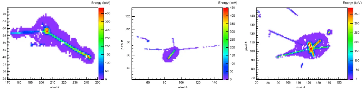
The Timepix3 produces well defined annihilation signatures. Annihilation products produce clear tracks which are isotropically distributed. The high dynamic range of the ASIC allows correct tagging of both pion (MIPs – Minimum Ionizing Particles) and heavy fragment tracks.Fig. 7shows a selection of events, produced by ∼1 keV antiprotons. The average energy of annihilation pro-ducts is in the range of ∼100 MeVs[5]. At these energies, only pions are MIPs, hence it is possible to directly identify them within the observed events. Information on the kind of product can often be obtained also for highly ionizing particles, depending on the presence of a Bragg peak and the observed track length[4].
The clear signature of antiproton annihilations obtained with
the Timepix3 can be used for material fragmentation studies, i.e. by interposing thin foils on the detector surface. The information on the energy of the incoming antiprotons via the TOA allows to be sure that the annihilations take place within the foil volume and not on the detector surface. Such studies will be performed in the next data taking runs.
The TOA information produced by the Timepix3 can also be exploited to obtain 3D information on the direction of the track vectors. The pixels within a single annihilation event were ob-served to have a TOA spread in the order of 40 ns, compatible with the carrier drift time traversing up to 675 μm Si thickness from the nþimplant to the pþpixelated junctions. Moreover the far ends of the observed tracks had generally a lower TOA than the annihi-lations centers. This is expected from the annihilation taking place on the detector nþ side, given the low kinetic energy of the in-coming antiprotons: the charge carriers generated on the far end of the detector will have to drift over the whole detector thickness. In our case the detection threshold was set at 4 keV, well below the expected charge released by a MIP in a sideways path through a 55 μm pixel (∼14 keV). With MIPs-induced tracks, with relatively low values of deposited charge, the ToA for the pixels closer to the annihilation vertex (i.e. the detector backplane, where the anni-hilation is taking place) is comparable to the expected drift time for holes over the whole 675 μm bulk thickness. This is likely caused by the fact that the integrated charge pulse exceeds the discriminator threshold only in very close proximity of the pixel junction due to the peaking of the pixel's weighting field in this region.
Knowing the applied bias and the depletion voltage and using the Jacoboni parametrization for hole mobility[10]we were able to generate a time-depth lookup table. The 3D reconstruction of one annihilation event with three pions is shown in Fig. 8. The accuracy of the z information is dependent from the accuracy in the modelling of the electric field as well as the biasing conditions of the detector (lower bias voltages corresponding to longer drift times can increase the resolution – at the cost of a higher charge smearing due to diffusion effects) and has to be evaluated on a per-detector basis. However, the information (here with an esti-mated accuracy of 4% – calculated as ratio between the ToA re-solution and the drift time) is always sufficient to unambiguously define the direction vector of the annihilation prongs.
6. Conclusions and outlook
We have shown results obtained using the first implementation of a new low energy antiproton extraction line implemented in the Time [ns] 0 1000 2000 3000 4000 5000 Normalized counts 0 0.002 0.004 0.006 0.008 0.01 0.012 0.014 0.016 1000 V 2000 V 5000 V
Pixel time distribution
Fig. 5. Integrated time distribution of fired pixels for different applied deflector voltages.
AEgIS experimental area. The simple concept of the line allows for quick mounting and implementation of setups making use of such antiprotons. The extraction line is able to provide monoenergetic antiproton beams, with a low background. Further improvements will be commissioned in the future (larger acceptance to incoming antiprotons and improved electrostatic optics), mainly in order to increase the flux.
We have employed this beamline for validating the use of the Timepix3 readout ASIC for direct annihilation detection. The ASIC, coupled with a relatively thick, 675 μm, sensor, showed a large acceptance to annihilation fragments. Moreover we proved the capabilities of the Timepix3 as a silicon drift chamber when oper-ated to detect antiproton annihilations. Its TOA resolution provides the ASIC with the unique capability of determining the depth of the antiproton annihilations and the angles at which annihilation products are emitted.
Though large datasets were acquired, their heterogenous to-pology will require further analysis and the results will be the subject of a dedicated publication, especially in order to define the
best reconstruction strategies for the annihilation position.
Acknowledgements
This work was supported by DFG research Grant, excellence initiative of Heidelberg University, ERC under the European Unions Seventh Framework Program (FP7/2007-2013)/ ERC Grant Agree-ment nos. 291242 and 277762, Austrian Ministry for Science, search and Economy, Research Council of Norway, Bergen Re-search Foundation, Istituto Nazionale di Fisica Nucleare (INFN-Italy), John Templeton Foundation, Ministry of Education and Sci-ence of the Russian Federation and Russian Academy of SciSci-ences, European social fund within the framework of realizing the pro-ject: Support of inter-sectoral mobility and quality enhancement of research teams at Czech Technical University in Prague, CZ.1.07/ 2.3.00/30.0034. 25 30 35 40 45 50 55 60 65 70 0 50 100 150 200 250 300 350 400 40 60 80 100 120 0 50 100 150 200 250 300 350 400 450 70 80 170 180 190 200 210 220 230 240 250 60 80 100 120 140 90 100 110 120 130 140 150 70 80 90 100 110 120 130 140 0 50 100 150 200 250 300 350 pixel # pixel # Energy (keV) Energy (keV) Energy (keV) pixel # pixel # pixel # pixel #
Fig. 7. Sample frames for some topologies of annihilation events. From left to right: two heavily ionizing particles with Bragg peak production, three MIPs and one heavy fragment, five heavily ionizing particles (one with a clear Bragg peak) and one MIP.
Pixel # [X coord.] 90 100 110 120 130 140 150 160 Pixel # [Y coord.] 10 20 30 40 50 60 70 80 90 Depth[ µm] 0 100 200 300 400 500 600 Pixel # (Y coord.) Pixel # (X coord.) 50 100 150 200 250 0 20 40 60 80 100 Pixel # (X coord.) Depth [µ m] 0 100 200 300 400 500 600 Pixel # (Y coord.) 50 100 150 200 250 50 100 150 200 250 50 100 150 200 250 Depth [ µm] 0 100 200 300 400 500 600
Fig. 8. Isometric view and XY, XZ and YZ projections (left to right, top to bottom) of an annihilation event. The z coordinate was obtained by correlating the carrier drift time with the generation depth, as explained in the text.
References
[1] G. Drobychev, et al., in: CERN-SPSC-2007017, 2007 〈http://cdsweb.cern.ch/re cord/1037532〉.
[2] M. Doser, et al., Exploring the WEP with a pulsed cold beam of antihydrogen, Class. Quantum Grav. 29 (2012) 184009,http://iopscience.iop.org/article/10. 1088/0264-9381/29/18/184009.
[3]S. Baird, et al., Nucl. Instrum. Methods Phys. Res. A 391 (1997) 210.
[4] S. Aghion, et al., Journal of Instrumentation 9 (2014) P06020.
[5]N. Pacifico, et al., Investigation of silicon sensors for their use as antiproton annihilation detectors, Nucl. Instrum. Methods Phys. Res. A 765 (2014) 161. [6] A. Gligorova, et al., IEEE Trans. Nucl. Sci. NS-61 (6) (2014) 3747.
[7] T. Poikela, et al., J. Instrum. 9 (2014) C05013. [8] ADVACAM Official Website 〈http://www.advacam.com〉.
[9] Ion Beam Simulator Official Website 〈http://ibsimu.sourceforge.net〉. [10]C. Jacoboni, et al., Solid State Electron. 20 (2) (1977) 77.