Politecnico di Milano
Scuola di Ingegneria Industriale e dell’Informazione
Corso di Laurea Magistrale in Ingegneria Informatica
Dipartimento di Elettronica, Informazione e Bioingegneria
A Stealth, Selective, Link-layer Denial-of-Service
Attack Against Automotive Networks
Relatore: Prof. Stefano ZANERO
Tesi di laurea di:
Andrea PALANCA Matr. 823482
In loving memory of my mother, Attilia Colombo (1956 - 2013). You may not be with me anymore, but you shall forever thrive in my mind.
Abstract
Modern vehicles incorporate tens of electronic control units (ECUs), driven by, according to estimates, as much as 100,000,000 lines of code. They are tightly interconnected via internal networks, mostly based on the CAN bus standard. Past research showed that, by obtaining physical access to the network or by remotely compromising a vulnerable ECU, an attacker could control even safety-critical inputs such as throttle, steering or brakes. In order to secure current CAN networks from cyberattacks, detection and prevention approaches based on the analysis of transmitted frames have been proposed, and are generally considered the most time- and cost-effective solution, to the point that companies have started promoting aftermarket products for existing vehicles.
This thesis presents a selective denial-of-service attack against the CAN standard which doesn’t involve the transmission of any frames for its execu-tion, and thus would be undetectable via frame-level analysis. As the attack is based on CAN protocol weaknesses, all CAN bus implementations by all man-ufacturers are vulnerable, even outside of the automotive world. Moreover, the attack can also be performed completely remotely under easily achievable assumptions. In order to precisely investigate the time, money and expertise needed, an experimental proof-of-concept against a modern, unmodified vehi-cle is implemented and it is proved that the barrier to entry is extremely low. Finally, this paper presents a discussion of the threat analysis, and proposes possible countermeasures for detecting and preventing such an attack.
Unfortunately, since the attack is rooted on design weaknesses, the viable countermeasures are far from a «plug-and-secure» approach. Instead, they imply significant changes in how CAN networks are typically deployed. The hope is that future generation CAN networks will be designed taking into account the possibility of attacks such as the one that it is presented.
Sommario
L’automobile, di gran lunga il mezzo di trasporto più utilizzato sulla Ter-ra, nel corso degli anni è stata oggetto di profonde modifiche e miglioramenti: dall’evoluzione delle architetture motoristiche ai fini di migliori consumi di car-burante o di energia elettrica senza sacrificare le prestazioni, agli sviluppi della struttura dello pneumatico allo scopo di garantire aderenza in tutte le possibili condizioni del manto stradale; dalla scelta di materiali strutturali sempre più leggeri ma allo stesso tempo capaci di assorbire una quantità di energia sem-pre più alta in caso di incidente, all’applicazione di studi di aerodinamica per ottenere contemporaneamente la massima efficienza e deportanza possibili.
Nonostante sia imprescindibile l’apporto dato dai progressi sopracitati (e non), l’aspetto che ha maggiormente rivoluzionato il mondo dell’automobile negli ultimi 40 anni è stata l’integrazione sempre più massiccia di elettronica e software. Partendo dai primi sistemi di iniezione del carburante e proseguendo verso i primi sistemi di antibloccaggio delle ruote in frenata (ABS), l’automo-bile si è dotata in maniera sempre più evidente di computer predisposti alla gestione di ogni singolo suo aspetto, con il risultato che una moderna berlina dispone di decine di centraline elettroniche di controllo (ECU), connesse tra loro tramite una o più reti interne tendenzialmente basate sul protocollo CAN, e di centinaia di milioni di righe di codice.
Seppur riconosciute e statisticamente rilevanti le migliorie apportate da tali sistemi, l’aggiunta sempre più ingente di computer per la gestione di aspetti anche critici del veicolo ha inevitabilmente portato con sé problemi di natura di sicurezza informatica, problemi tutt’altro che ignoti al mondo dell’ICT ma inediti nel mondo dell’automobilismo. Una combinazione di pressioni econo-miche per il rilascio sempre più solerte di nuovi prodotti sul mercato, esigenze di integrazione di componenti di diversi fornitori, adempienza alle norme di legge, l’aggiunta sempre più preponderante sulle centraline della vettura di interfacce comunicanti con il mondo esterno, una scarsa o persino totalmente
assente metodologia d’approccio verso il problema della sicurezza informatica ed una frenetica ricerca del profitto necessaria per la sopravvivenza in un mer-cato estremamente competitivo hanno portato negli ultimi anni alla comparsa sui veicoli di vulnerabilità informatiche sempre più concretamente fattibili da sfruttare per un eventuale aggressore.
Vulnerabilità che, come testimoniano i precedenti numerosi studi compiuti da ricercatori di sicurezza informatica, possono portare alla capacità di con-trollare in maniera arbitraria e, in alcuni casi, persino totalmente da remoto, sistemi critici della vettura quali acceleratore, sterzo e freni, ponendo guidatore e passeggeri potenzialmente in grave pericolo.
La stragrande maggioranza degli attacchi informatici dimostrati sinora da ricercatori di sicurezza consiste, tramite connessione fisica alla vettura o tra-mite compromissione da remoto di una centralina già presente a bordo della macchina, nella contraffazione ed invio indiscriminato di messaggi (in termi-ne tecnico, frame) all’interno della rete CAN dell’automobile con lo scopo di compromettere in maniera vantaggiosa per l’avversario il funzionamento del veicolo. L’attacco tramite iniezione di frame, nella stragrande maggioranza dei casi, consiste nella generazione e trasmissione di frame standard (normal-mente impiegati all’interno delle comunicazioni di rete della vettura) ad un rateo ben superiore del normale, con lo scopo di convincere la centralina sotto attacco ad ignorare i messaggi legittimi, oppure di frame di diagnostica, ai fini di portare la centralina sotto attacco in uno stato non standard e fare da essa eseguire operazioni di collaudo non sicure in situazioni di uso normale della vettura con conducente a bordo (un esempio è la modifica della posizione della pinza freno rispetto al disco, operazione prevista da alcuni produttori per ef-fettuare diagnosi sui freni a macchina ferma ma che, se effettuata con veicolo in movimento, può portare a situazioni pericolose).
A causa della natura di tali attacchi e della topologia bus della rete CAN, il modo considerato più efficiente per rendere sicura a sufficienza (almeno allo stesso livello di sicurezza di un attacco fisico su altri aspetti della vettura) un’auto da attacchi informatici consiste nell’installazione di un sistema di in-dividuazione o di prevenzione delle intrusioni (IDS/IPS), che monitora ogni messaggio circolante sulla rete della macchina ed attua contromisure qualora stabilisca, con un livello di probabilità sufficientemente alto, l’esecuzione di un attacco in corso. Seppur non trascurabile la barriera in ingresso per lo sviluppo e l’impiego di un tale sistema di sicurezza da parte di un produttore automobilistico, precedenti studi compiuti da ricercatori di sicurezza hanno
ampiamente dimostrato la fattibilità e l’efficacia di tali sistemi nel riconoscere e prevenire attacchi di iniezione di frame all’interno di una rete CAN.
Nel seguente lavoro di tesi, viene presentato un innovativo attacco di nega-zione del servizio (DoS) contro il protocollo CAN che non prevede l’inienega-zione di alcun frame all’interno della rete della macchina, risultando di conseguenza po-tenzialmente in grado di aggirare tutti i sopracitati IDS/IPS basati sull’analisi di frame.
L’attacco sfrutta una caratteristica intrinseca del protocollo CAN, ovvero la capacità per un bit dominante di sovrascrivere sempre un bit recessivo, e fa leva su due sue «fragilità», ovvero il sistema di gestione degli errori ed il sistema di confinamento automatico di centraline malfunzionanti. Il risultato è la possibilità per un eventuale avversario di bloccare qualunque messaggio circolante all’interno della rete della macchina tramite l’invio di 1 singolo bit dominante sovrascritto al posto di un qualunque bit recessivo del messaggio, e la possibilità di disattivare totalmente le comunicazioni di qualunque centralina connessa alla rete CAN della macchina tramite un minimo di 32 sovrascritture di un qualunque messaggio mandato da tale centralina.
Essendo l’attacco basato su falle di sicurezza proprie del protocollo, ogni implementazione del protocollo CAN da parte di ogni produttore è vulnerabile, comprese applicazioni al di fuori dell’ambiente automobilistico (il protocollo CAN, ad esempio, è usato per la gestione automatizzata delle attrezzature all’interno delle sale operatorie di ospedali o per la supervisione telemati-ca all’interno delle industrie di macchinari basati sui protocolli DeviceNet o CANopen).
L’attacco può avvenire mediante connessione fisica alla rete interna della vettura (ad esempio, tramite l’aggiunta di un dispositivo alla porta OBD-II della macchina, obbligatoria per legge, oppure attraverso il collegamento diretto alla rete CAN di una nuova centralina compromessa) oppure anche da remoto (tramite la riprogrammazione remota di una centralina già presente all’interno della vettura) e non può essere rilevato né fermato in una normale moderna rete CAN salvo una profonda riprogettazione della stessa.
Allo scopo di comprovare la validità della tesi, è stato concretamente porta-to a termine (e viene accuratamente documentaporta-to all’interno di quesporta-to lavoro di tesi) un attacco contro una moderna automobile completamente di serie attraverso l’aggiunta di un dispositivo alla porta OBD-II della macchina, di-mostrando peraltro un’allarmante fattibilità in termini di spesa monetaria, tempo e conoscenze richieste per la sua realizzazione.
La parte conclusiva di questa tesi è dedicata alla discussione dei possibili pericoli derivanti dall’attuazione di un tale attacco nel mondo reale, all’analisi degli scenari nei quali la realizzazione dell’attacco potrebbe risultare fattibile da parte di un eventuale aggressore ed alla presentazione di possibili contromi-sure per poter rilevare e, possibilmente, bloccare l’attacco dall’essere compiuto.
Contents
1 Introduction 1
1.1 The Evolution of the Car Architecture . . . 1
1.2 Towards Automotive Security . . . 2
1.3 The Contribution of this Work . . . 4
2 Controller Area Network (CAN) Bus 6 2.1 Introduction . . . 6
2.2 Protocol Overview . . . 6
2.3 Historical Background . . . 8
2.4 Physical Layer Description . . . 9
2.4.1 Introduction . . . 9
2.4.2 Architecture . . . 10
2.4.3 Signaling Levels . . . 11
2.4.4 Network Specifications . . . 12
2.5 Data Link Layer Description . . . 13
2.5.1 Introduction . . . 13 2.5.2 Message Framing . . . 13 2.5.2.1 Data Frame . . . 14 2.5.2.2 Remote Frame . . . 15 2.5.2.3 Error Frame . . . 15 2.5.2.4 Overload Frame . . . 16 2.5.2.5 Interframe Space . . . 17
2.5.3 Frame Identifier, Bus Arbitration and Message Priority . 17 2.5.4 Message Validation . . . 19
2.5.5 Bit Timing . . . 19
2.5.6 Bit Stuffing . . . 20
2.6 Applications of CAN Bus . . . 21
Contents
2.6.1.1 Motivations . . . 21
2.6.1.2 Automotive Messages Taxonomy . . . 21
2.6.1.3 Active Safety Systems . . . 22
2.6.2 Other Applications . . . 22
3 Background 24 3.1 Prior Studies . . . 24
3.2 Proposed Countermeasures . . . 28
3.3 Related Work . . . 30
4 Protocol Analysis and Attack Description 32 4.1 Introduction . . . 32
4.2 CAN Error Handling Weakness Description . . . 33
4.2.1 CAN Specification . . . 33
4.2.2 Weakness Analysis . . . 34
4.3 CAN Fault Confinement Weakness Description . . . 34
4.3.1 CAN Specification . . . 34
4.3.2 Weakness Analysis . . . 37
4.4 Technical Requirements . . . 37
4.5 Proposed Attack Algorithm . . . 39
4.5.1 Algorithm Presentation . . . 39
4.5.2 Setup Algorithm . . . 39
4.5.3 RXD Falling Edge ISR Algorithm . . . 40
4.5.4 Timer Expiration ISR Algorithm . . . 40
5 Experimental Proof-of-Concept Implementation and Testing 43 5.1 Introduction . . . 43
5.2 Target Identification . . . 44
5.3 CAN Traffic Analysis . . . 46
5.3.1 Introduction . . . 46
5.3.2 Scantool OBDLink SX Setup . . . 48
5.3.3 Giulietta CAN Capturing . . . 50
5.3.4 Target Frame Identification . . . 52
5.4 Attacking Device Implementation . . . 53
5.4.1 Introduction . . . 53
5.4.2 Components Overview . . . 53
5.4.2.1 Arduino Uno Rev 3 . . . 53
Contents
5.4.2.3 SAE J1962 Male Connector . . . 56
5.4.3 Implementation . . . 58
5.4.3.1 Uno Complete Source Code . . . 58
5.4.3.2 Uno Source Code Analysis . . . 60
5.4.3.3 Wires Soldering and Final Architecture . . . 69
5.5 On Bench Testing . . . 72
5.5.1 Introduction . . . 72
5.5.2 Attack Test . . . 72
5.5.3 Reliability Measurement . . . 73
5.5.3.1 Introduction . . . 73
5.5.3.2 CANtact Python Wrapper Complete Source Code 74 5.5.3.3 CANtact Python Wrapper Source Code Analysis 75 5.5.3.4 OBDLink SX Python Wrapper Complete Source Code . . . 77
5.5.3.5 OBDLink SX Python Wrapper Source Code Analysis . . . 80
5.5.3.6 Python CAN Fuzzer/Checker Complete Source Code . . . 81
5.5.3.7 Python CAN Fuzzer/Checker Source Code Anal-ysis . . . 84
5.5.3.8 Test Execution and Final Results . . . 85
5.6 On Vehicle Testing . . . 87
6 Threat Model Discussion and Remediation Approach 91 6.1 Introduction . . . 91
6.2 Threat Assessment . . . 91
6.2.1 Introduction . . . 91
6.2.2 Active Safety Systems Attacks . . . 92
6.2.3 Car Ransom . . . 92
6.2.4 Theft Support . . . 94
6.3 Threat Vectors Analysis . . . 94
6.3.1 Introduction . . . 94
6.3.2 Local Vectors . . . 95
6.3.2.1 Introduction . . . 95
6.3.2.2 Malicious OBD-II Devices . . . 95
6.3.2.3 Malicious Directly Attached Nodes . . . 96
Contents
6.4 Detectability and Countermeasures . . . 98
6.4.1 Introduction . . . 98 6.4.2 Attack Detection . . . 98 6.4.2.1 Before Execution . . . 98 6.4.2.2 While/After Execution . . . 100 6.4.3 Attack Prevention . . . 100 6.4.3.1 Introduction . . . 100 6.4.3.2 Network Segmentation . . . 100
6.4.3.3 Diagnostic Port Access Control . . . 101
6.4.3.4 Network Topology Alteration . . . 101
6.4.3.5 Encryption . . . 101
6.4.3.6 Other Protocols . . . 102
7 Future Work 103
8 Conclusion 105
List of Figures
1.1 Modal split of inland passenger transport in Europe in 2013. . 2
1.2 Features controlled by ECUs in a modern premium sedan. . . . 3
1.3 Lines of code in modern vehicles compared to aircrafts. . . 3
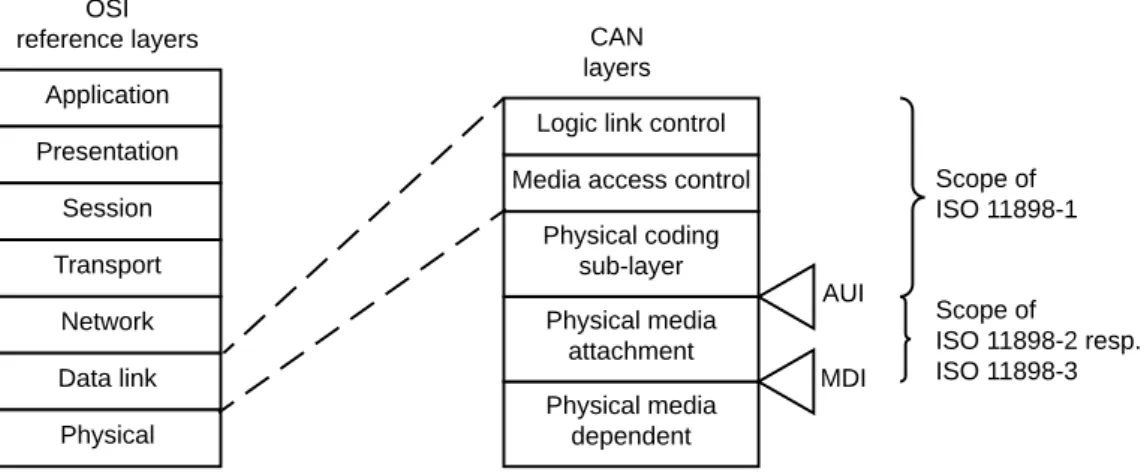
2.1 CAN link and physical layers relation to OSI model. . . 7
2.2 The 1989 BMW 8 Series grand tourer coupè. . . 9
2.3 Example architecture of an ISO 11898-2 CAN network. . . 10
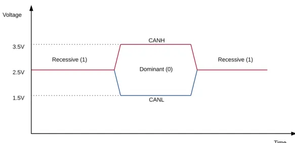
2.4 ISO 11898-2 electrical levels and respective signaling states. . . . 12
2.5 An ISO 11898-2 transceiver block diagram. . . 13
2.6 CAN data frame format. . . 14
2.7 CAN remote frame format. . . 15
2.8 CAN error frame format. . . 16
2.9 CAN overload frame format. . . 16
2.10 CAN interframe space format. . . 17
2.11 CAN arbitration algorithm example. . . 18
2.12 Partition of the CAN bit time. . . 19
2.13 Euro NCAP Roadmap 2016-2020. . . 22
2.14 The 2002 Ducati 999 sport bike. . . 23
3.1 Cherokee hack headline on Wired. . . 27
3.2 Examples of commercial automotive IDSs/IPSs solutions. . . 29
3.3 sfiCAN architecture. . . 30
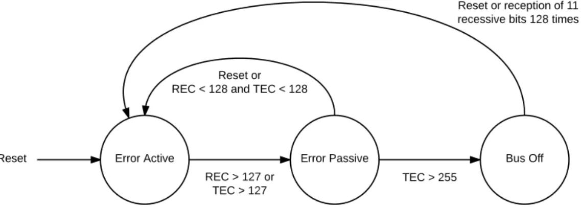
4.1 CAN fault confinement finite state machine. . . 37
4.2 Attacking node required architecture. . . 38
4.3 Visualization of the proposed attack algorithm on a time graph. 42 5.1 The Alfa Romeo Giulietta employed for the test. . . 45
5.2 Architecture of the Giulietta’s internal CAN networks. . . 45
List of Figures
5.4 The Giulietta’s OBD-II port. . . 47
5.5 The Scantool OBDLink SX USB-to-OBDII cable. . . 48
5.6 The FCA cars CAN B OBD-II adapter and its schematic. . . 49
5.7 Giulietta CAN traffic capturing. . . 50
5.8 The Arduino Uno Rev 3. . . 54
5.9 Arduino Uno Rev 3 pinout. . . 55
5.10 The Microchip MCP2551 E/P. . . 55
5.11 Microchip MCP2551 block diagram. . . 57
5.12 The SAE J1962 Male Connector. . . 57
5.13 Schematic of the crafted attacking device. . . 70
5.14 The attacking device after wires soldering. . . 71
5.15 On bench test CAN setup. . . 73
5.16 The attacking device attached to the Giulietta’s OBD-II port. . 88
5.17 The parking sensors malfunction on driver’s LCD. . . 88
6.1 The compromised Uconnect system of a Jeep Cherokee. . . 93
6.2 Architectures of local attacks via malicious OBD-II devices. . . 95
6.3 Architectures of local attacks via malicious attached nodes. . . . 96
6.4 Architectures of remotely attacked nodes. . . 97
List of Tables
5.1 Giulietta Full Model Specifications. . . 44
5.2 Giulietta Brief Technical Specifications. . . 44
5.3 Arduino Uno Rev 3 Technical Specifications. . . 54
5.4 Microchip MCP2551 E/P Technical Specifications. . . 56
5.5 TIMSK2 - Timer/Counter2 Interrupt Mask Register Structure. . 63
5.6 TCCR2A - Timer/Counter2 Control Register A Structure. . . . 64
5.7 TCCR2B - Timer/Counter2 Control Register B Structure. . . . 64
5.8 TIFR2 - Timer/Counter2 Interrupt Flag Register Structure. . . 65
5.9 EIMSK - External Interrupt Mask Register Structure. . . 65
5.10 EICRA - External Interrupt Control Register A Structure. . . . 66
5.11 EIFR - External Interrupt Flag Register Structure. . . 66
5.12 PORTD - Port D Data Register Structure. . . 68
5.13 PIND - Port D Input Pins Address Register Structure. . . 69
List of Algorithms
4.1 CAN Denial-of-Service Setup Algorithm. . . 39 4.2 CAN Denial-of-Service RXD Falling Edge ISR. . . 40 4.3 CAN Denial-of-Service Timer Expiration ISR. . . 41
Listings
5.1 Scantool OBDLink SX setup. . . 48
5.2 Scantool OBDLink SX CAN capturing commands. . . 50
5.3 Examples of Giulietta CAN B frames in various conditions. . . . 51
5.4 The Giulietta CAN B frame sent by the parking sensors module. 52 5.5 Arduino Uno Rev 3 complete source code. . . 58
5.6 CANtact Python wrapper complete source code. . . 74
5.7 OBDLink SX Python wrapper complete source code. . . 77
5.8 Python CAN fuzzer/checker complete source code. . . 81
5.9 Start of the CAN fuzzer/checker, first error and end. . . 86
Chapter 1
Introduction
1.1
The Evolution of the Car Architecture
By far, road vehicles are the most popular mode of transport in the world. According to official statistics from Eurostat [33] and from USA Bureau of Transportation [21], cars, motorcycles, trucks and coaches are on average adopted four times more than rail, air or sea for passenger transfers (Fig. 1.1). Among these, cars are the most preferred: Considering only legally reg-istered automobiles, in 2015 there were 1,776,136,357 vehicles circulating on Earth [87], and this number is expected to grow even more in the near future. Cars have massively evolved over the years. The well known saying «four wheels and an engine», by which automobiles are sometimes referred, is to-day by all means completely inadequate to describe the technological state to which cars have leaped, thanks to decades of research. Improvements in active and passive safety systems have almost halved road casualties in the USA with respect to 40 years ago [6], enhancements in powertrain technologies and aero-dynamics have resulted in road legal vehicles capable of very high performance on a race track and impressive fuel efficiency on a road [81] and autonomous cars are no longer solely in the realm of science fiction [84].
Though by no means diminishing other paramount enhancements in the car universe, the most radical changes cars have witnessed in the last four decades are owed to the ever increasing addition of electronics and software. Starting from the late seventies with the first and relatively simple (at least if compared to modern standards) engine control units, responsible for regu-lating fuel injection systems in order to meet the increasingly stringent laws on emissions [5], embedded systems have rapidly pervaded throughout the car
1.2. Towards Automotive Security
Figure 1.1: Modal split of inland passenger transport in Europe in 2013 [32].
and now, by communicating among each other via an internal network - the most common of which, today, is CAN bus -, supervise every aspect of it, from telematics units to steering, from airbags deployment to central locking, from heating, ventilation and air conditioning to autonomous active safety systems (Fig. 1.2). Modern cars are equipped with an average of 50 electronic control units (ECUs) and 100 million lines of code, and these numbers are barely going to stabilize or decrease in the future [82] (Fig. 1.3).
1.2
Towards Automotive Security
Albeit irreproachable the contribution of embedded computers to overall cars improvement, the unavoidable consequence of this increased complexity and co-presence of electronic and computer based components is a wider dig-ital attack surface. A combination of time to market pressures, integration needs of components from manifold distinct suppliers, laws abidance, outside world interfaces requirements, poor or even absent security concerns and fran-tic cost reduction originated a totally new set of vulnerabilities (new to the car
1.2. Towards Automotive Security
WiFi/Internet Connectivity Autonomous Cruise Control
Mobile App Remote Control Adaptive Front Lighting System
Lane Departure Warning System Tire Pressure Monitoring System
Electronic Throttle Control AM/FM/Digital/Satellite/Internet Radio Airbags
Electronic Stability Control Antilock Braking System
Advanced Emergency Braking Blind Spot Monitor
Parking Sensors Active Suspensions Regenerative Braking Self Parallel Parking Key-less Entry System Anti-theft System
Power Adjustable Seats Electric Power Steering
Bluetooth Smartphone Connectivity Automatic Windshield Wipers
Satellite Assisted Navigation Digital Instrument Panel Cluster
Figure 1.2: Overview of the features typically controlled by ECUs in a modern premium sedan [71].
Figure 1.3: Average lines of software code in modern luxury vehicles compared to types of aircraft [78].
industry, yet most of them well known by the majority of IT companies) that a potential adversary might exploit for malicious intents. Indeed, in the last decade the number of automotive security studies and reported possible exploit vectors - even completely remote and Internet based - has increased exponen-tially [26, 36, 45, 52, 53, 79], to the point that «car hacking» is now being taken into serious consideration by, for instance, US government agencies [19,78] and government acts for strengthening automotive cybersecurity regulations [3] or bills for specifically sanctioning unauthorized access to vehicles have already been proposed [10].
Most attacks published so far share a common point: the leverage of a vulnerability (or a chain of vulnerabilities) with the aim of indiscriminately sending messages into the internal car network and proving that it is possi-ble to alter the behavior of safety-critical elements such as engine, brakes or steering. Fortunately, the frame based nature of these attacks makes them effectively recognizable by proper intrusion detection or prevention systems (IDSs/IPSs), which monitor all messages circulating on the network and
trig-1.3. The Contribution of this Work
ger countermeasures in case they detect that an attack is in progress. Although it is acknowledged that the adoption barrier of IDS/IPS technologies into car networks is significant, previous work [27, 52, 78, 79] has shown the feasibility of porting classic intrusion detection methodologies to the automotive domain and car cybersecurity companies have already proposed aftermarket solutions for existing vehicles [15, 77].
1.3
The Contribution of this Work
This thesis presents a novel denial-of-service attack against the CAN bus standard which is inherently harder to detect, as it exploits the design of the CAN protocol itself at a low level, and can selectively cause malfunctions of safety-critical components or completely disable vehicle functionalities (e.g., electronic stability control, electric power steering).
The attack works between the physical and data link layers of the OSI stack, without requiring any message sending capability to the adversary. As such, it is completely undiscoverable without a major restructuring of current CAN bus networks.
Since the attack exploits design weaknesses of the CAN protocol, any im-plementation and manufacturer is vulnerable. Moreover, CAN adoption goes beyond the automotive domain, including critical applications such as fac-tory automation (e.g., CANopen or DeviceNet based machinery), building automation (e.g., elevator management), and hospitals (lights, beds, X-Ray machines) [23, 24]. Therefore, the opportunities for an attacker to connect to a CAN bus network are all but scarce.
The attack works locally, through the standard diagnostic port, which is mandatory in essentially every country [59], or via a tampered/counter-feited replacement part, and remotely. Therefore, the attacker model is rather generic, including for example a malicious mechanic, a malicious OTA firmware upgrade, a malicious passenger or driver in a car sharing (or even self driving car) setting, and similar scenarios.
In order to precisely evaluate the required time, level of expertise and cost, a proof-of-concept of the attack was concretely implemented against a modern, unaltered production vehicle (an Alfa Romeo Giulietta) and it is proved that it can be efficiently and conveniently mounted against a specific frame with 99.9974 % accuracy using a development board as simple as an Arduino Uno.
1.3. The Contribution of this Work
In the end, this paper discusses examples of possible threats to car occu-pants, examines which are potential attack vectors and real world scenarios where such attack could be staged by attackers and proposes possible remedi-ation approaches.
In summary, this thesis makes the following contributions:
• It describes a stealth, denial-of-service attack against the CAN standard to which all CAN bus implementations are vulnerable;
• It demonstrates the attack feasibility by implementing a low cost proof-of-concept against an unmodified vehicle and includes full source code release to the community;
• It proposes practical solutions for detecting the attack in existing CAN networks and discusses possible network modifications for preventing it in future vehicles.
Chapter 2
Controller Area Network
(CAN) Bus
2.1
Introduction
The Controller Area Network (CAN) bus is a multimaster asynchronous soft realtime serial bus standard designed for allowing communication of mul-tiple microcontrollers with each other.
It was originally developed by Robert Bosch Gmbh, released to the public in 1986 and then standardized in 1993 by the International Organization for Standardization as ISO 11898 [42, 62].
Today, it is the de facto leading standard for ECUs communications in vehicles: Almost all automobiles on the market feature at least one CAN network as a backbone for the interconnection of embedded systems.
This chapter provides an in depth summary of the CAN protocol. It starts by portraying the fundamental properties which guided its design, gives a brief outlook over its history, analyzes the protocol physical and data link layers main characteristics and ends by presenting the most important applications of CAN in a great variety of engineering sectors.
2.2
Protocol Overview
According to the original Bosch specification, the main properties of CAN are:
2.2. Protocol Overview Application Presentation Session Transport Network Data link Physical OSI reference layers Physical media dependent CAN layers Physical media attachment Physical coding sub-layer Media access control
Logic link control
AUI MDI Scope of ISO 11898-1 Scope of ISO 11898-2 resp. ISO 11898-3
Figure 2.1: CAN data link and physical sub-layers relation to the OSI model. Please notice: ISO 11898-2 refers to a yet to be released future version that will incorporate current ISO 11898-2, ISO 11898-5 and ISO 11898-6 parts of ISO 11898 standard [42].
• guarantee of latency times; • configuration flexibility;
• multicast reception with time synchronization; • system wide data consistency;
• multimaster;
• error detection and signaling;
• automatic retransmission of corrupted messages as soon as the bus is idle again;
• distinction between temporary errors and permanent failures of nodes and autonomous switching off of defect nodes.
The ISO standard covers both physical and data link layers, as reported in Figure 2.1, and comprises six parts:
Part 1: defines the data link layer including the logical link control (LLC) sub-layer and the medium access control (MAC) sub-layer, as well as the physical signaling (PHS) sub-layer;
2.3. Historical Background
Part 3: defines the low-speed fault-tolerant physical medium attachment (PMA);
Part 4: defines the time-triggered communication;
Part 5: defines the power modes of the high-speed physical medium attach-ment (PMA);
Part 6: defines the selective wake-up functionality of the high-speed physical medium attachment (PMA).
2.3
Historical Background
CAN bus history dates back to the early 1980s. At that time, embedded systems were more and more growing in popularity among car manufacturers due to the extended capabilities and lower costs they offered with respect to completely mechanical or electronic hard coded controllers, but the engendered wire harnesses because of direct point to point connections between nodes were shortly becoming a significant issue in terms of weight, reliability and mainte-nance costs [54]. This influenced Robert Bosch GmbH, a German engineering and electronics company with an emphasis on the automotive industry, to start analyzing a variety of bus protocols with the aim of finding an appropriate one to deploy in road vehicles, without success.
As a result, in 1983, under the guide of Uwe Kiencke [9], manager of the company advanced systems development department, Bosch initiated the cre-ation of an all new bus standard. The pursued main objectives were noise immunity, broadcast communications, a low cost and lightweight backbone network, priority handling with limited delay for critical messages, error de-tection and fault confinement capabilities. In the development, engineers from Mercedes-Benz and Intel were involved. The name «Controller Area Network» was due to Professor Dr. Wolfhard Lawrenz, from the University of Applied Science in Braunschweig-Wolfenbüttel, hired as a consultant.
Three years later, in February 1986, at the Detroit SAE congress, Uwe Kiencke, Siegfried Dais, and Martin Litschel introduced the «Automotive Serial Controller Area Network». The protocol was welcomed with great enthusiasm by most automotive stakeholders.
One year later, in mid 1987, Intel delivered the first CAN controller chip, the 82526, specifically designed for automotive applications.
2.4. Physical Layer Description
Figure 2.2: The 1989 BMW 8 Series grand tourer coupè [55].
In early September 1989, the Frankfurt Motor Show witnessed the debut of the world’s first CAN bus equipped vehicle, the BMW 8 Series grand tourer coupè (Fig. 2.2), which, thanks to the restricted wire harnesses due to the CAN standard bus topology, could boast a weight saving of over 45 kilograms with respect to non CAN based direct competitors such as the Mercedes-Benz SL R129 [69].
The Bosch CAN specification was submitted for international standardiza-tion in the early 1990s and, after political issues concerning the concurrent Vehicle Area Network (VAN) bus protocol simultaneously developed by PSA and Renault, was eventually standardized as ISO 11898 in November 1993 [23].
2.4
Physical Layer Description
2.4.1
Introduction
The original CAN specification gave only abstract requirements for the physical layer. This freed the protocol from the burdens and the complexities of mandating a common physical implementation which could have limited its adoption. Nonetheless, it left CAN bus implementations open to interoperabil-ity issues due to incompatibilities among different suppliers, that were later - partially, as mechanical protocol aspects are still lacking of standardizing guidelines - solved with ISO 11898-2 and ISO 11898-3.
2.4. Physical Layer Description R 120? R 120? CAN Transceiver CANL CANH CAN Controller Microcontroller ... CAN Transceiver Microcontroller with built-in CAN Controller CAN Transceiver CAN Controller Microcontroller
Engine Control Module
Infotainment Body Control Module
RXD TXD TXD RXD RXD TXD
Figure 2.3: Example architecture of an ISO 11898-2 CAN network.
2.4.2
Architecture
Today, most CAN buses are characterized by the topology specified in ISO 11898-2, also called «high speed CAN»: a two wire, CANH (high) and CANL (low), differential balanced signaling scheme featuring a termination at each end by means of a 120 ohm resistor. The differential signaling allows for noise immunity; the balanced signaling means that the current flowing in each signal line is equal but opposite in direction, resulting in the necessary field-canceling effect to obtain low noise emissions [72].
Each CAN node generally comprises three elements (Fig. 2.3):
Microcontroller: is responsible for sending and processing complete CAN frames to and from the CAN controller and supervising the CAN con-troller operation;
CAN controller: is in charge of correctly implementing the CAN specifica-tions. It synchronizes with the CAN signal, sends and receives logical data to and from the CAN transceiver, automatically adds stuff bits, performs error handling and actualizes the error modes finite state ma-chine;
2.4. Physical Layer Description
CAN transceiver: serves as an interface between the CAN controller and the physical bus by translating logical signals coming from the CAN controller into bus electrical levels.
In the recent years, the trend which has characterized automotive specific mi-crocontrollers is to embed the CAN stack on chip, for both cost effectiveness and space saving reasons [47]. Thus, there exist microcontrollers with em-bedded CAN controllers and microcontrollers which even feature the entire stack on chip (i.e. CAN controller and CAN transceiver incorporated inside a microcontroller [56]).
Though less popular, CAN buses can also be single wire (e.g., standard SAE J2411 [66]). Because of their better error resiliency, two wire buses are preferred, especially in safety-critical applications.
Moreover, in case physical faults tolerance is an essential requirement of the application, the International Organization for Standardization also proposed the ISO 11898-3 standard, called low speed or fault tolerant CAN, which uses a linear bus, star bus or multiple star buses connected by a linear bus and is terminated at each node by a termination resistance of 100 ohm. However, up to now, the adoption of ISO 11898-3 CAN buses has been limited to few niche segments in the automotive world. Today, the general automotive tendency is to substitute ISO 11898-3 CAN transceivers with ISO 11898-2 transceivers with low-power functionality and, fundamentally, to design new CAN networks in compliance with the ISO 11898-2 standard [22].
2.4.3
Signaling Levels
The CAN standard mandates two different signaling states that can be written on the bus: dominant and recessive, with the former capable of anytime overwriting the latter; that is, whenever a dominant bit is sent at the same time as a recessive bit, the bus state and thus the logical signal perceived by all other CAN nodes is dominant. Most CAN bus implementations feature a wired-AND configuration, hence the dominant bit is the logical 0 whereas the recessive bit is the logical 1. The distinguishing factor between a dominant state and a recessive state is the differential voltage between the CANH and the CANL lines (Fig. 2.4). In case such difference doesn’t exceed a threshold value (usually 0.9 V in ISO 11898-2 networks), a recessive state (thus most times 1) is presumed, else a dominant state (0).
2.4. Physical Layer Description 1.5V 2.5V 3.5V Voltage Time CANH CANL Recessive (1) Recessive (1) Dominant (0)
Figure 2.4: Typical ISO 11898-2 electrical levels and their respective signaling states.
During a recessive state, the signal lines and resistors remain in a high impedance states and voltages on both CANH and CANL tend weakly towards a midway value, usually 2.5 V. During a dominant condition, the signal lines and resistors move to a low impedance state so that current flows through the resistor, CANH voltage tends to 3.5 V and CANL tends to 1.5 V (Fig. 2.5).
2.4.4
Network Specifications
The ISO 11898-2 standard supports communications transfer rates up to 1 Mbps (i.e. minimum nominal bit time of 1 us). However, because of un-avoidable skews due to the physical required time for the signal to travel in the transmission medium from one end to the other and the bus nature of CAN which requires all nodes to be synchronized, transfer speeds are restricted by cable length. Approximately, 500 kbps are achievable only in buses up to 100 meters, 250 kbps up to 200 m, 125 kbps up to 500 m and only 10 kbps up to 6 km [46].
The cable impedance is required to be 120 ohm, though values in the in-terval of [108;132] ohm are still permitted.
As aforementioned, no connectors have been mandated up to now. As a result, an array of interfaces has been proposed and utilized, varying with respect to higher layer adopted protocols. The most common are the 9 pin D-Sub, the de facto industrial standard, the 5-pin Mini-C and Micro-C, employed by DeviceNet and SDS appliances, and the RJ10 and RJ45, proposed by CiA
2.5. Data Link Layer Description
Figure 2.5: An ISO 11898-2 transceiver block diagram [73].
in the CANopen standard CiA-303-1 [25].
2.5
Data Link Layer Description
2.5.1
Introduction
Most of CAN standard focuses on the data link layer, acting as an interface between upper layers and the physical one. It has originally and thoroughly been described in the Bosch specification document, although with a few am-biguities that were later clarified in the ISO 11898-1 standard.
2.5.2
Message Framing
The standard describes four types of frames: data frames, remote frames, error frames and overload frames. Data frames and remote frames are char-acterized by two variants: standard frame format (which uses an 11 bit frame identifier, defined in Bosch CAN 2.0 part A) and extended frame format (which uses a 29 bit frame identifier, defined in Bosch CAN 2.0 part B).
2.5. Data Link Layer Description
Figure 2.6: CAN data frame format [62].
2.5.2.1 Data Frame
The data frame, reported on Figure 2.6, carries data from the transmitter to all receivers.
A data frame is composed of:
Start of Frame: 1 dominant bit, allows hard synchronization of all nodes;
Arbitration Field: if standard format is employed, is made up of (in this order): frame identifier (11 bits), remote transmission request (1 domi-nant bit). If extended format is utilized, is composed of (in this order): frame base identifier (11 bits), substitute remote request (1 recessive bit), identifier extension (1 recessive bit), extended frame identifier (18 bits), remote transmission request (1 dominant bit). The role of the arbitration field is described in subsection 2.5.3;
Control Field: if standard format, in this order: identifier extension (1 dom-inant bit), reserved bit r0 (1 domdom-inant bit), data length code (4 bits). If extended format, in this order: reserved bits r1 and r0 (2 dominant bits), data length code (4 bits). The data length code defines the number of bytes carried in the data field, with a maximum value of 8 bytes;
2.5. Data Link Layer Description
Figure 2.7: CAN remote frame format [62].
CRC Field: in this order: CRC sequence (15 bits), CRC delimiter (1 reces-sive bit). Permits messages integrity checks by all receiving nodes; ACK Field: in this order: ACK slot (1 bit), ACK delimiter (1 recessive bit).
The ACK slot bit is sent as recessive by the transmitter, all receivers must overwrite it with a dominant bit in case the message has up to now been correctly received;
End of Frame: 7 recessive bits, notifying the end of the transmission.
2.5.2.2 Remote Frame
A remote frame is transmitted by a node to request a new data frame with the sent identifier (Fig. 2.7).
All fields behave in the same way as in the data frame, with the exception of the remote transmission request - which is now 1 recessive bit -, the data length code which carries the number of bytes of the to be sent data frame -and the lack of the data field.
2.5.2.3 Error Frame
The error frame, shown in Figure 2.8, is sent by any node whenever a bit error, a stuff error, a CRC error, a form error or an acknowledgment error (or
2.5. Data Link Layer Description
Figure 2.8: CAN error frame format [62].
Figure 2.9: CAN overload frame format [62]. a combination of these) has been detected (discussed in chapter 4).
An error frame consists of:
Error Flag: 6 bits, dominant or recessive depending on the current CAN controller error state;
(Superposition of Error Flags): eventual overlapping of error flags sent by different stations at different moments;
Error Delimiter: 8 recessive bits, indicating the end of the error frame.
2.5.2.4 Overload Frame
The overload frame purpose is to delay the transmission of succeeding data frames or remote frames (Fig. 2.9).
An overload frame comprises: Overload Flag: 6 dominant bits;
(Superposition of Overload Flags): eventual overlapping of overload flags sent by different stations at different moments;
2.5. Data Link Layer Description
Figure 2.10: CAN interframe space format [62].
2.5.2.5 Interframe Space
Data frames and remote frames are mandatorily separated from preceding frames (of whichever type) by an interframe space, reported on Figure 2.10.
An interframe space contains: Intermission: 3 recessive bits;
(Suspend Transmission): 8 recessive bits, sent only by error passive nodes;
Bus Idle: an arbitrary length of recessive bits, signaling that the bus is free and ready to transport new frames. Nodes can anytime send a new frame on the bus by asserting the start of frame dominant bit.
2.5.3
Frame Identifier, Bus Arbitration and Message
Priority
In contrast with many other protocols, CAN bus, at least at the data link layer (upper layers, such as ISO 15765 [41], have implemented mitigating so-lutions on top of it to overcome this problem for their specific purposes) and with the only exception of remote frames which, nevertheless, are rarely em-ployed in normal CAN traffic, is characterized by the complete lack of any addressing mechanism, i.e. messages don’t contain any «sender» or «receiver» fields. Rather, the CAN standard operates in a «publish-and-subscribe» fash-ion. Messages, on the basis of their sender and their content, are tagged with a unique label written by their transmitters in their frame identifier fields and then are broadcast. Receivers monitor all messages circulating on the bus and filter the frames they are interested in precisely on the basis of the frame identifier content.
2.5. Data Link Layer Description
Logical Value Sent
Time Node 1 Node 2 Node 3 SoF Loses arbitration Loses arbitration
Wins arbitration and continues message transmission 0 1 Frame Identifier Bus Idle 0 1 1 1 1 1 0 0 0 0 0 1
Figure 2.11: CAN arbitration algorithm example.
The design choice of opting for a publish and subscribe mechanism instead of a classic sender-receiver approach was necessary due to another requirement that CAN had to fulfill, namely colliding messages arbitration biased in favor of higher priority frames.
As a matter of fact, due to the bus topology, a CAN network is a unique collision domain. All CAN nodes are required not to interfere in any way with CAN traffic in case another unit is transmitting a message; however, when the bus is idle, two or more nodes may (and are allowed to) simultaneously start sending new frames, generating a collision.
The solution to the bus arbitration problem stands exactly in the unique-ness of the frame identifier field and in the overwriting capability of dominant bits over recessive bits.
All nodes, when transmitting any message, continuously analyze the logi-cal signal on the bus and compare them with the bit value they are trying to assert; should a difference be found, the node is mandated to back off, commu-nicate the anomaly by sending an error frame (apart when this happens in the arbitration field or in the ACK slot of a frame) and retry the message trans-mission as soon as the bus returns idle. As a consequence, after sending the start of frame bit, all contending CAN nodes confront themselves on the basis of the identifiers of the frames they are trying to transmit: the one sending
2.5. Data Link Layer Description
Figure 2.12: Partition of the CAN bit time [62].
the frame with the lowest identifier won’t notice any discrepancy and will con-tinue broadcasting the message without losing neither time nor information; the other units will withdraw and will afterwards retry the transmission (Fig. 2.11).
Therefore, besides distinguishing messages, the identifier is also responsi-ble for the precedence among frames: the lower the identifier, the higher the priority of that message with respect to other contending transmissions.
2.5.4
Message Validation
As aforementioned, the transmitter of a message continually monitors the bus and compares the perceived signal levels with the transmitted ones. In addition to solving bus contests, this feature is employed for error checking purposes. More in depth, a message is valid for its transmitter if no error has been detected for the whole transmission of the frame. Should any error be observed, retransmission will follow automatically - according to prioritization - as soon as the bus is free again.
A message is valid for the receivers if there is no error until the last bit prior to the end of frame field. The value of the end of frame bit is considered a «don’t care» and a dominant level does not lead to a form error.
2.5.5
Bit Timing
CAN is asynchronous, i.e. it lacks a clock signal line. In order to avoid nodes drifting issues and achieve synchronization, the standard describes bit timing guidelines that CAN controllers must implement.
In particular, each bit on the CAN bus must be considered as composed of minimal periods of time called time quanta, whose length varies among nodes
2.5. Data Link Layer Description
and is multiple of each oscillator period. Time quantas are clustered into four non-overlapping segments (Fig. 2.12):
Synchronization segment: always one quantum long, is used to synchronize nodes on the bus;
Propagation segment: compensates physical delays among nodes;
Phase segment 1 and phase segment 2: fix edge phase errors on the bus, their length can be adjusted.
The bus levels are always sampled between phase segment 1 and phase segment 2.
Synchronization is achieved in two ways:
Hard synchronization: performed when there is a recessive to dominant edge after a bus idle condition, indicating a start of frame bit. All re-ceiving nodes bit time counters are restarted;
Resynchronization: executed whenever a bit edge doesn’t occur within the synchronization segment in a message. As a result, phase segments are lengthened (or shortened) by an integer number of quanta in order to correct the phase error in the signal.
2.5.6
Bit Stuffing
CAN uses a non-return-to-zero encoding, implying that not every bit con-tains a falling or rising edge. This means that the signal level can remain constant over a very long period of time if the transmitted bits have the same logical value, resulting in the impossibility for all CAN nodes to synchronize themselves via resynchronization. In order to overcome this problem, CAN employs a stuff bit rule: Whenever a transmitter detects five consecutive iden-tical bits to be transmitted, it automaiden-tically inserts a following complementary bit in the transmitter bit stream; whenever the receiving nodes detect five con-secutive identical bits on the bus, they automatically discard the following one. This way it is guaranteed that the original bit sequence isn’t altered by any means while at the same time enabling synchronism via resynchronization.
2.6. Applications of CAN Bus
2.6
Applications of CAN Bus
2.6.1
Automotive Industry
2.6.1.1 Motivations
Without any doubt, the most important applications of CAN bus are to be seen in the automotive world, which is the specific domain for which CAN has been designed. Starting from 1989 with the BMW 8 Series, the first produc-tion car to incorporate a CAN network for ECUs interconnecproduc-tion, CAN has relentlessly been adopted by more and more car manufacturers, to the point that almost all automobiles today on the market feature at least one CAN network as a backbone for embedded systems communications. CAN allowed for extremely cost-effective component integration thanks to the general pur-pose ability of carrying data for a great variety of applications, the remarkable reduction of wire harnesses due to the bus topology with respect to direct hard wired connections and extremely competitive chip prices. In addition to that, it permitted fast data transfer rates (up to 1 Mbps), higher than most concurrent standards, and was suitable for communications of soft realtime applications.
2.6.1.2 Automotive Messages Taxonomy
Generally, in today’s production vehicles, CAN is employed to carry two types of messages:
Standard messages: frames exchanged among two or more ECUs in regular communications in order to mutually coordinate for the correct execu-tion of an applicaexecu-tion. For example, the frames exchanged by the radio frequency hub module with the door modules to implement keyless en-try systems or by the driving support module with the instrument panel cluster and the electric power steering module to implement lane depar-ture warning systems, which correct the vehicle trajectory and alert the driver in case the car involuntarily starts drifting into a parallel lane; Diagnostic messages: frames usually exchanged among a diagnostic device
connected to the car internal network (for instance via the mandatory [59] OBD-II port) and one or more ECUs for diagnostic sessions. For example, for vehicle emissions testing sessions or, in case of some vehicle malfunctioning, for checking diagnostic trouble codes.
2.6. Applications of CAN Bus
Figure 2.13: Euro NCAP Roadmap 2016-2020 [31].
2.6.1.3 Active Safety Systems
Notably, one of the major purposes which led to the ever increasing accep-tance of CAN by car manufacturers for modules communications is to be found in active safety systems. The purpose of active safety systems is to reactively (and even proactively) realtime intervene and correct car inputs on behalf of car driver to avoid/mitigate the effects of an accident or to partially lighten her from the burdens of continuously operating with the car commands, for instance in long travels on highways. In the past, active safety systems used to be offered as standard equipment only on luxury vehicles and as optional on premium automobiles; however, due to the acknowledgment of the effec-tiveness of such systems in terms of road casualties and injuries reduction, governments started mandating a minimal presence of active safety systems on all cars sold on their national market [35] and, contemporarily, national crash test evaluation agencies began incentivizing their adoption by means of safety ratings boosts [30,31] (Fig. 2.13), with the result that, today, apart from niche segments or in very underdeveloped countries, it is almost impossible to find new cars which are devoid of any.
2.6.2
Other Applications
Notwithstanding, CAN is not only limited to automobiles.
2.6. Applications of CAN Bus
Figure 2.14: The 2002 Ducati 999 sport bike [1].
implemented by a higher and higher number of motorcycle manufacturers due to the weight saving induced by the restrained wire harnesses.
CAN bus has also been employed for developing train-wide communica-tion networks [11], for instance in linking the door units, for brake controllers coordination or for passenger counting units; in maritime, for control-by-wire of ships; in avionics, for flight-state sensors, navigation systems or communi-cations with research PCs in the cockpit; or in aerospace, for fuel systems, pumps or linear actuators [54].
Outside of the transportation universe, CAN has been used for the most dif-ferent applications, from regulating CANopen or DeviceNet based industrial machinery networks (packaging machines, knitting systems or for semicon-ductor manufacturing) to managing operating rooms equipment in hospitals (lights, beds, X-Ray machines) or controlling elevators in modern, automated buildings [23, 24].
Chapter 3
Background
3.1
Prior Studies
In the last 10 years, the focus on automotive security and the number of published security analyses by academic researchers or field experts has steadily been increasing, due to the constant addition and coupling of embed-ded systems inside vehicles and the inclusion of more and more interfaces with the outside world which started raising concerns on what would happen in case vulnerabilities should be discovered.
This section reports an overview comprising the majority of previously conducted attacks on automotive networks and studies about CAN security, ordered by publication year.
• «Security in Automotive Bus Systems», Marko Wolf, André Weimer-skirch, and Christof Paar, 2004. The first analysis of automotive bus sys-tems with respect to their security against various malicious attacks [85]; • «CANcentrate: An active star topology for CAN networks», Manuel Barranco, Guillermo Rodriguez-Navas, Luis Almeida, and Julian Proenza, 2004. A study on the implementation and dependability of a star variant of CAN bus [17];
• «State of the Art: Embedding Security in Vehicles», Marko Wolf, Andre Weimerskirch, and Thomas Wollinger, 2006. A research on the application of IT security protocols and best practices on automotive networks [86];
3.1. Prior Studies
EDR», Peter Thom, and Arthur MacCarley, 2008. An analysis about privacy concerns on automotive event data recording [76];
• «On the Power of Power Analysis in the Real World: A Com-plete Break of the KeeLoq Code Hopping Scheme», Thomas Eisenbarth, Timo Kasper, Amir Moradi, Christof Paar, Mahmoud Salma-sizadeh, and Mohammad T. Manzuri Shalmani, 2008. A side channel dif-ferential power analysis attack on KeeLoq, a remote keyless entry system block cipher [29];
• «Security and Privacy Vulnerabilities of In-Car Wireless Net-works: A Tire Pressure Monitoring System Case Study», Ishtiaq Rouf, Rob Miller, Hossen Mustafa, Travis Taylor, Sangho Oh, Wenyuan Xu, Marco Gruteser, Wade Trappe, and Ivan Seskarb, 2010. A study over the security of tire pressure monitoring systems [63];
• «Security threats to automotive CAN networks - Practical ex-amples and selected short-term countermeasures», Tobias Hoppe, Stefan Kiltz, Jana Dittmann, 2010. The first research on practical frames injection attacks over windows lifts, warning lights, airbags control sys-tems and central car gateways, provided car physical access, and possible countermeasures that can be applied, including the first usage proposal of IDSs for detecting attacks in automotive networks [40];
• «Experimental Security Analysis of a Modern Automobile», Karl Koscher, Alexei Czeskis, Franziska Roesner, Shwetak Patel, Ta-dayoshi Kohno, Stephen Checkoway, Damon McCoy, Brian Kantor, Danny Anderson, Hovav Shacham, and Stefan Savage, 2010. The first prac-tical frames injection attack over a car CAN networks, provided car physical access, which resulted in arbitrary control by the attacker of safety-critical vehicle commands including throttle or brakes, even by-passing the driver inputs [45]. This and the previous researches were very coldly welcomed by the automakers community, despite the gravity of the claims, due to physical access being required in both situations; • «Comprehensive Experimental Analyses of Automotive Attack
Surfaces», Stephen Checkoway, Damon McCoy, Brian Kantor, Danny Anderson, Hovav Shacham, Stefan Savage, Karl Koscher, Alexei Czeskis,
3.1. Prior Studies
Franziska Roesner, and Tadayoshi Kohno, 2011. The world’s first com-pletely remote attack on an utterly unmodified vehicle and an experimen-tal analysis over the vectors, such as OBD-II port, CD player, bluetooth connected smartphone or cellular connectivity, via which an attack could be mounted [26];
• «Designing sfiCAN: a star-based physical fault injector for CAN», David Gessner, Manuel Barranco, Alberto Ballesteros, and Julián Proenza, 2011. A study and preliminary implementation of a physical fault injec-tor for CAN networks that allows the simulation of a great variety of complex fault scenarios [39];
• «Enhancing Security in CAN Systems using a Star Coupling Router», Roland Kammerer, Bernhard Fromel, and Armin Wasicek, 2012. A study over the security of a star coupling router and an analysis of its trust model to overcome security deficiencies present in bus-based CAN systems [44];
• «Adventures in Automotive Networks and Control Units», Chris Valasek, and Charlie Miller, 2013. A technical white paper describing practical frames injection attacks, provided cars physical access, on two modern vehicles, again leading to the attacker capability of manipulating car safety-critical inputs, including throttle, brakes and steering. Rein-forces usage of IDSs for detecting attacks [79]. Again, not much taken into consideration by car manufacturers due to physical access require-ment;
• «A Survey of Remote Automotive Attack Surfaces», Charlie Miller, and Chris Valasek, 2014. A technical white paper analyzing the feasibility of conducting remote attacks over a variety of different vehicles from different manufacturers, based on internet retrieved material [52];
• «Remote Exploitation of an Unaltered Passenger Vehicle», Char-lie Miller, and Chris Valasek, 2015. Arguably the most famous «car hacking» attack, conducted completely remotely on an unmodified 2014 Jeep Cherokee being driven on a public highway [53]. Highly covered by mass media [83] (Fig. 3.1), led to Fiat Chrysler Automobiles massive recall of 1.4 million vehicles for bug fixing [18];
3.1. Prior Studies
Figure 3.1: The Cherokee remote hack headline on Wired online magazine [83].
• «Fast and Vulnerable: A Story of Telematic Failures», Ian Foster, Andrew Prudhomme, Karl Koscher, and Stefan Savage, 2015. A study over the security of a telematics OBD-II dongle, whose compromise led to the attacker ability to perform frames injection attacks again resulting in remote control of safety-critical inputs [36];
• «The Art of Bit-Banging: Gaining Full Control of (Nearly) Any Bus Protocol», Aaron Waibel, 2016. A research over the vulnerability of many bus systems (and also CAN) to «bit banging» attacks [80]; • «Fingerprinting Electronic Control Units for Vehicle Intrusion
Detection», Kyong-Tak Cho, and Kang G. Shin, 2016. A proof-of-concept discussion and implementation of an intrusion detection
sys-3.2. Proposed Countermeasures
tem capable of distinguishing CAN frames spoofing attacks by analyzing CPUs clocks behaviors [27];
• «Lock It and Still Lose It —on the (In)Security of Automotive Remote Keyless Entry Systems», Flavio D. Garcia, David Oswald, Timo Kasper, and Pierre Pavlidés, 2016. An analysis over the security of remote keyless entry systems based on rolling codes and examples of remote control cloning attacks [38];
• «Truck Hacking: An Experimental Analysis of the SAE J1939 Standard», Yelizaveta Burakova, Bill Hass, Leif Millar, and André Weimerskirch, 2016. In the same fashion as many experimental secu-rity studies conducted on cars, the world’s first practical attacks on a truck and a school bus based on the SAE J1939 standard [20, 65]; • «A Security Analysis of an In-Vehicle Infotainment and App
Platform», Sahar Mazloom, Mohammad Rezaeirad, Aaron Hunter, and Damon McCoy, 2016. A study over the security of an in-vehicle infotain-ment system and its low resilience to digital attacks which could lead to the adversary’s ability to send malicious messages into the car internal network [49].
3.2
Proposed Countermeasures
In order to overcome the road vehicles security issues unveiled thus far, possibly in as short time as possible, a survey conducted in March 2016 by the United States Government Accountability Office [78] among major industry stakeholders identified the following countermeasures that could be possibly applied in order to mitigate the impact of potential attacks:
Trusted Computing Base: hardware security modules or trusted software in order to preserve and guarantee ECUs integrity;
Network Segmentation: critical ECUs decoupling from non safety-critical ECUs or from ECUs featuring external interfaces by confining them in different networks and inter-networks communications restric-tions via firewalls/gateways to solely allow a selected list of trusted frames to be broadcast from less trusted to more trusted networks;
3.2. Proposed Countermeasures
(a) Argus IDPS [15]. (b) TowerSec ECUSHIELD [77].
Figure 3.2: Examples of commercial automotive IDSs/IPSs solutions.
Cryptography: by means of ECUs code signing or frames encryption and authentication;
Intrusion Detection or Prevention Systems (IDSs, IPSs): security ap-pliances that monitor network traffic, try to establish if an attack is in progress and, in case of prevention systems, attempt to stop it automat-ically.
Among these, IDSs/IPSs are currently believed to be the most time- and cost-effective solution for circumventing eventual security threats in CAN net-works. Indeed, CAN frames injection attacks are based either on the trans-mission of normal frames at a much higher rate than usual (the reason is due to the fact that spoofed frames will be sent at the same time as legitimate frames. Thus, in order to trick the receiving ECU into considering only the maliciously crafted messages, these must be sent at a faster rate with respect to the rightful ones) or on the transmission of diagnostic frames, not expected to be seen in standard circumstances, hence both readily recognizable by proper IDSs/IPSs. In addition to that, the bus topology of CAN networks makes the addition of IDSs/IPSs into current architectures effortless with respect to network segmentation or cryptography implementations which would require complete network redesign, to the point that companies have already devel-oped aftermarket IDSs/IPSs for current generation vehicles [15, 77] (Figures 3.2a and 3.2b).
3.3. Related Work
Figure 3.3: sfiCAN architecture [39].
3.3
Related Work
The idea of mounting denial-of-service attacks against CAN networks is not a novelty in the automotive security research field. Indeed, in the aforemen-tioned papers, examples of DoS attacks via frames injection (either by sending frames with the highest possible priority in order to indefinitely delay other nodes transmissions or frames which counteract driver inputs) have been pro-posed. However, these kinds of attacks would be easily detected by IDSs/IPSs and, possibly, blocked as well, making them potentially harmless in IDS/IPS secured automotive networks. As described in the next section, the solution proposed in this paper doesn’t imply any frame sending but exploits the bus nature and fragile CAN protocol rules to mount the attack.
This type of attack has theoretically been proposed in some existing liter-ature. In «Security in Automotive Bus Systems» [85], the authors explore the feasibility of performing frameless denial-of-services by sending well directed error flags into the CAN network, forcing other nodes to reject a message. In «Enhancing Security in CAN Systems using a Star Coupling Router» [44] the authors also briefly touch on the fact that similar consequences could also arise in case a corrupted node arbitrarily upset CAN traffic bits. In «The Art of Bit-Banging: Gaining Full Control of (Nearly) Any Bus Protocol» [80] many bus networks (including CAN) are described as being vulnerable to «bit bang-ing» attacks. However, in all those studies the attack was described from a purely theoretical point of view, without any proof-of-concept implementation nor in depth threat model analysis.
To the best of the author’s knowledge, the only prior work which proposed an implementation of a mechanism capable of inserting faults in CAN net-works is «Designing sfiCAN: a star-based physical fault injector for CAN », in
3.3. Related Work
2011 [39] (Fig. 3.3). Yet, the research focused on injecting errors in CAN net-works for preproduction testing purposes only and didn’t cover any automotive related security considerations. In addition to that, in order to perform such fault injections, the network had to be topologically altered to a not ordinary star schema, tampering which a potential attacker is not expected to perform in a reasonable amount of time. In this work, no modifications are assumed: The attack can be conducted in any unaltered CAN-enabled car.
Chapter 4
Protocol Analysis and Attack
Description
4.1
Introduction
The CAN protocol started being developed in 1983 and was ultimately released to the public in 1986. In an utter similar fashion to what occurred within the IT industry in its first years, the CAN protocol was devised with
safety in mind, rather than security. Simplicity, physical faults tolerance,
flexibility and performance were its guiding principles, with attacks resistance or intrusions avoidance being taken into very little consideration. After all, in no way could Bosch engineers envisage that CAN in the future would have supported a network of so tightly coupled and so heterogeneous embedded systems, some of which featuring external interfaces with the outside world that could lead to trust concerns. This led to weak security wise design choices, which, as previously stated, the last decade researches are gradually bringing to surface.
This chapter presents two weaknesses of the CAN standard, related to the CAN error handling and CAN automatic fault confinement policies, respec-tively. These flaws generated the two security vulnerabilities which have been exploited by the proposed denial-of-service attack. For both of them, the Bosch CAN specifications [62] and an in depth analysis are reported. The other two sections of this chapter are devoted to the description of the attacking node architecture and its minimum technical requirements necessary for mounting the attack and to the presentation of the attack algorithm itself.
4.2. CAN Error Handling Weakness Description
4.2
CAN Error Handling Weakness
Descrip-tion
4.2.1
CAN Specification
There are 5 different error types (which are not mutually exclusive): Bit Error: A unit that is sending a bit on the bus also monitors the bus. A
bit error has to be detected at that bit time when the bit value that is monitored is different from the bit value that is sent. An exception is the sending of a recessive bit during the stuffed bit stream of the arbitration field or during the ACK slot. Then no bit error occurs when a dominant bit is monitored. A transmitter sending a passive error flag and detecting a dominant bit does not interpret this as a bit error;
Stuff Error: A stuff error has to be detected at the bit time of the 6th con-secutive equal bit level in a message field that should be coded by the method of bit stuffing;
CRC Error: The CRC sequence consists of the result of the CRC calculation by the transmitter. The receivers calculate the CRC in the same way as the transmitter. A CRC error has to be detected, if the calculated result is not the same as that received in the CRC sequence;
Form Error: A form error has to be detected when a fixed-form bit field contains one or more illegal bits. (Note, that for a receiver a dominant bit during the last bit of end of frame is not treated as form error); Acknowledgment Error: An acknowledgment error has to be detected by
a transmitter whenever it does not monitor a dominant bit during the ACK slot.
A station detecting an error condition signals this by transmitting an error flag. For an error active node it is an active error flag, for an error passive node it is a passive error flag.
Whenever a bit error, a stuff error, a form error or an acknowledgment error is detected by any station, transmission of an error flag is started at the respective station at the next bit.
![Figure 1.1: Modal split of inland passenger transport in Europe in 2013 [32].](https://thumb-eu.123doks.com/thumbv2/123dokorg/7501515.104527/18.892.154.743.123.538/figure-modal-split-inland-passenger-transport-europe.webp)
![Figure 1.2: Overview of the features typically controlled by ECUs in a modern premium sedan [71].](https://thumb-eu.123doks.com/thumbv2/123dokorg/7501515.104527/19.892.150.734.137.344/figure-overview-features-typically-controlled-ecus-modern-premium.webp)
![Figure 2.6: CAN data frame format [62].](https://thumb-eu.123doks.com/thumbv2/123dokorg/7501515.104527/30.892.150.743.125.454/figure-can-data-frame-format.webp)
![Figure 2.8: CAN error frame format [62].](https://thumb-eu.123doks.com/thumbv2/123dokorg/7501515.104527/32.892.145.750.130.565/figure-can-error-frame-format.webp)
![Figure 2.12: Partition of the CAN bit time [62].](https://thumb-eu.123doks.com/thumbv2/123dokorg/7501515.104527/35.892.152.749.129.316/figure-partition-bit-time.webp)
![Figure 2.14: The 2002 Ducati 999 sport bike [1].](https://thumb-eu.123doks.com/thumbv2/123dokorg/7501515.104527/39.892.150.743.129.528/figure-ducati-sport-bike.webp)
![Figure 3.1: The Cherokee remote hack headline on Wired online magazine [83].](https://thumb-eu.123doks.com/thumbv2/123dokorg/7501515.104527/43.892.172.731.171.638/figure-cherokee-remote-hack-headline-wired-online-magazine.webp)