Science Advice for Policy by European Academies
Novel carbon
capture and
utilisation
technologies
SAPEA Evidence Review Report No. 2
Informs the European Commission Group of Chief Scientific Advisors Scientific Opinion No. 4/2018
Novel carbon
capture and
utilisation
technologies
This Evidence Review Report has been produced under the auspices of the SAPEA Consortium, as a deliverable under Grant Agreement Nr 737432 “Science Advice for Policy by European Academies” (SAPEA) that was signed by the Consortium and the European Commission on 22 November 2016. The text of this work is licensed under the terms of the Creative Commons Attribution licence which permits unrestricted use, provided the original author and source are credited. The licence is available at: http://creativecommons.org/licenses/by/4.0. Images are not covered by this licence.
This report can be viewed online at: www.sapea.info/CCU The following experts contributed to the report:
Robert Schlögl (Chair), Fritz-Haber-Institute, Germany Carlos Abanades, Spanish Research Council, Spain Michele Aresta, CIRCC, University of Bari, Italy
Adisa Azapagic, University of Manchester, United Kingdom
Edd Anders Blekkan, Norwegian University of Science and Technology, Norway Thibault Cantat, CEA, France
Gabriele Centi, University of Messina, Italy Neven Duic, University of Zagreb, Croatia Aïcha El Khamlichi, ADEME, France
Graham Hutchings, Cardiff University, United Kingdom Marco Mazzotti (Co-chair), ETH Zürich, Switzerland Unni Olsbye, University of Oslo, Norway
Hrvoje Mikulcic (invited member), University of Zagreb, Croatia
In accordance with Article 35, paragraph 1 of the aforementioned Grant Agreement, the Consortium identified all relevant interests of the experts requested to contribute to the Evidence Review Report, assessed whether an interest constituted a conflict of interests, and took -where relevant- measures to exclude that an interest could compromise or be reasonably perceived as compromising the impartiality or objectivity of the report.
Further information about SAPEA’s working processes are available at: www.sapea.info/guidelines. The information, facts and opinions set out in this report are those of the authors and do not necessarily reflect the opinion of the European Commission. The SAPEA Consortium is not responsible for the use which may be made of the information contained in this report by anyone, including the European Union institutions and bodies or any person acting on their behalf.
PDF ISBN 978-3-9819415-5-5 DOI 10.26356/CARBONCAPTURE Print ISBN 978-3-9819415-4-8 ISSN 2568-4434
SAPEA, Science Advice for Policy by European Academies. (2018). Novel carbon capture and utilisation technologies: research and climate aspects Berlin: SAPEA. doi: 10.26356/CARBONCAPTURE
PUBLISHER SAPEA c/o acatech Pariser Platz 4a
CONTACT
SAPEA Communications Office 13 Rue d’Egmont
Spanning the disciplines of engineering, humanities, medicine, natural sciences and social sciences, SAPEA – Science Advice for Policy by European Academies – brings together outstanding knowledge and expertise from over 100 academies, young academies, and learned societies in over 40 countries across Europe.
SAPEA is part of the European Commission’s Scientific Advice Mechanism (SAM), which provides independent, interdisciplinary, and evidence-based scientific advice on policy issues to the European Commission. SAPEA works closely with the European Commission Group of Chief Scientific Advisors
This Evidence Review Report informed the Group of Chief Scientific Advisors Opinion
on Novel carbon capture and utilisation technologies: research and climate aspects,
which is available here:
http://ec.europa.eu/research/sam/pdf/sam_ccu_report.pdf
Funded through the EU’s Horizon 2020 programme, the SAPEA consortium comprises Academia Europaea (AE), All European Academies (ALLEA), the European Academies’ Science Advisory Council (EASAC), the European Council of Academies of Applied Sciences, Technologies and Engineering (Euro-CASE), and the Federation of European Academies of Medicine (FEAM).
For further information about SAPEA visit www.sapea.info.
About SAPEA
Table of Contents
Main Report
05
FOREWORD07
EXECUTIVE SUMMARY09
CCU REPORT09
A. Definition of CCU10
B. The CCU system11
C. CCU in the context of societal services11
D. Simplified system analysis of service delivery12
E. Framework for the assessment of CCU potential opportunities15
F. Analysis of technology chains16
G. Innovation needed17
H. Recommendations for actionTechnical Report
19
1. PREAMBLE22
2. INTRODUCTION22
2.1. Carbon dioxide Capture and Utilisation22
2.2. General considerations24
2.3. Assessment of the literature26
2.4. Data about energy and emissions28
2.5. Time scale of deployment31
2.5.1. Temporal resolution
32
2.6. Societal services32
2.7. Conceptual technology chains34
3. SYSTEM BOUNDARIES AND SYSTEMS ANALYSIS34
3.1. Scope of analysis34
3.2. Climate change mitigation potential36
3.2.1. Power-to-gas or power-to-liquid CCU systems using fossil sources of CO2
38
3.2.2. Power-to-gas or power-to-liquid CCU systems using renewable sources of CO2
40
3.2.3. Energy storage and/or distribution using CCU fuels
41
3.2.4. Breakthrough technologies using CO2 directly from the atmosphere
41
3.2.5. Manufacture of carbon products from CO2
42
3.3. Other environmental impacts42
3.4. Cost considerations44
3.5. Social aspects45
4. TECHNOLOGY OVERVIEW45
4.1. Power generation45
4.1.1. Natural gas
46
4.1.2. Hydrogen
46
4.1.3. Solar power
46
4.1.4. Wind power
47
47
4.2.1. Battery electric vehicles
48
4.2.2. Fuel cell electric vehicles
48
4.2.3. Natural gas vehicles
49
4.2.4. Methanol vehicles
49
4.3. CO2 capture
49
4.3.1. CO2 capture from concentrated point sources (CPS)
50
4.3.2. Direct CO2 capture from air (DAC)
50
4.4. H2 generation
50
4.4.1. Alkaline electrolyser
50
4.4.2. Proton exchange membrane (PEM) electrolyser
52
4.4.3. Solid oxide electrolyser
52
4.5. CO2 conversion
55
5. SIMPLIFIED SYSTEM ANALYSIS OF SERVICE DELIVERY
55
5.1. Technology chains to provide power and mobility services
55
5.1.1. 100% electrification
55
5.1.2. Hydrogen-based system
56
5.1.3. CCU
57
5.1.4. Comparison of alternative technology chains
58
5.2. Carbon fluxes, in the context of power and mobility services
59
5.2.1. Fossil-NG based L
60
5.2.2. Fossil-NG based with Carbon Dioxide Capture and Storage (CCS)
60
5.2.3. CCU for mobility
61
5.2.4. CCU for power generation
61
5.2.5. CCU for both mobility and power generation
62
5.2.6. Comparative assessment
62
5.2.7. Net-zero-emission natural gas-fired power plants
64
5.3. Storage and transport of renewable electricity
69
5.4. Manufacturing of industrial products
69
5.4.1. Alternative technology chains for carbon-bearing chemicals and materials
70
5.4.2. Minimisation of CO2 emissions via conversion
71
6. REQUIRED INNOVATIONS
71
6.1. Systemic aspects
72
6.2. Political boundary conditions
72
6.3. Technical gaps in knowledge
76
7. ASSESSMENT OF POTENTIAL
76
7.1. Methodology
77
7.2. Services and figures of merit
78
7.3. Options for action
79
7.3.1. Option 1
79
7.3.2. Option 2
80
7.3.3. Option 3
81
7.3.4. Concluding remarks
82
8. LITERATURE
89
9. GLOSSARY OF SELECTED ABBREVIATIONS
91
10. WORKING GROUP MEMBERS
92
11. ACKNOWLEDGEMENTS
Foreword
As the effects of climate change are becoming more visible, technologies for mitigating these effects are being sought. Do Carbon Capture and Utilisation (CCU)
technologies have the potential to contribute significantly to such mitigation efforts?
These technologies aim to extract CO2 either from concentrated sources such as the chimneys at coal- or natural gas-fired power stations, steel mills or cement factories or directly from the ambient air, and then use it as a raw material for carbon-containing products, such as fuels, chemical products, and building materials. At the same time, carbon dioxide is a notoriously inert molecule and conversion processes can be a highly energy intensive process and it is therefore crucial that this energy comes from carbon-free sources. This is the framework within which this report discusses CCU. Commissioner Miguel Arias Cañete (Climate Action & Energy) asked Carlos Moedas, Commissioner for Research, Science and Innovation to entrust the new Scientific Advice Mechanism and its scientific and engineering networks of European academies with the mandate of exploring the potential of CCU and provide a scientific opinion on the challenges and opportunities of novel carbon capture and utilisation technologies, thereby providing a direct link between scientific expertise and policy makers in the European Commission.
SAPEA set up an international Working Group of experts in the various domains concerned (energy systems, economy, chemistry, catalysis, electrolysis, etc.) that provided the necessary specialist knowledge about the concerned subjects. Euro-CASE was assigned the role of Lead Network in this project, acting as project manager to ensure high quality and timely outputs.
SAPEA is particularly indebted to the individual members of the Working Group and their unabated commitment to making the present body of knowledge and what it can tell us about potential future developments, supported by scientific and technological
Novel carbon capture and utilisation technologies: research
and climate aspects – a presentation of the results from the
SAPEA Working Group
advances, available to policy-makers. Special thanks go to Robert Schlögl, the Working Group Chair, and Marco Mazzotti, his Deputy, for presenting this knowledge in this report.
SAPEA, and in particular the Lead Academy Euro-CASE would like to thank the Group of Chief Scientific Advisors and the SAM Unit for their collaboration and continued support. The Scientific Opinion of the Group of Chief Scientific Advisors is based on this Evidence Review Report and, in order to broaden the evidence provided, on two workshops that were organised in addition to the Working Group: an External Expert Workshop (25 January 2018) and a Stakeholder Hearing (20 February 2018)
With this report, we hope to have contributed to far-reaching and visionary policy making in the field of CO2 management, energy, and climate action.
On behalf of SAPEA, we thank all those involved in bringing this project to completion, and particularly the individual members of the Working Group for their unrelenting commitment.
Prof. Bernard Charpentier,
Chairman of SAPEA and President of FEAM
Prof. Reinhard Hüttl,
SAPEA Board member and President of Euro-CASE
Executive Summary
This report aims, within the framework provided by the SAM/HLG Scoping Paper, to assess the climate mitigation potential of Carbon Capture and Utilisation (CCU), which is defined as “those technologies that use CO2 as a feedstock and convert it into value-added products such as fuels, chemicals or building materials”.
From a system perspective, CCU involves a number of steps, from capture of CO2 to its conversion into usable C-rich products, from the use of such products to their disposal as C-rich waste, and ultimately, CO2 re-emission – which may happen shortly after CO2 conversion (e.g. for synthetic fuels), or much later (e.g. for polymers). To power the CO2 capture and transformation processes and – in most cases – the synthesis of green-hydrogen as a co-reactant, C-free energy is needed. These processes consist of building blocks that also belong to other technology chains of interest for climate mitigation. As a consequence, CCU’s climate mitigation potential needs to be assessed from a systems perspective, and with regards to how it can provide societal services. These are defined here as (i) power generation and distribution through the grid, (ii) fuels (and power) for transport and mobility, (iii) long-term storage and long-range transport of intermittent renewable energies; and (iv) manufacturing of industrial products.
The report offers a simplified system analysis of service delivery, which highlights a few key features. 1) Using C-rich synthetic fuels requires the use of large amounts of Renewable Energy Sources (RES) and other carbon-free energies – much larger than what is required when RES electricity or green-hydrogen is used directly for consumption. 2) Such a decrease in efficiency in the use of RES may be acceptable in the provision of: a) C-rich synthetic fuels to power long-range aircraft and long-haul ships; and/or b) long-term storage and long-range transport of defossilised energy to compensate for the intermittency of RES. 3) For such uses, CCU-based solutions should be assessed in comparison with other alternative technologies that are beyond the scope of this report.
To consider the potential opportunities offered by CCU to European industries in supporting (i) climate change objectives, (ii) a circular economy, (iii) energy security and deployment of RES; and (iv) the evolution of CO2 capture systems, the report has defined an assessment framework. Such a framework identifies nine technology chains with respect to the generation and use of C-rich fuels and classifies them (according to a few first-order simplifying assumptions), based on whether they generate positive, net-zero, or negative CO2 emissions.
From the analysis of these technology chains, some key conclusions can be drawn: CCU may be part of a circular economy scheme where carbon atoms are recycled and re-used indefinitely over a long time scale. However, it is neither an indispensable element, nor is it sufficient, for a circular economy. True circular schemes are enabled
only when the CO2 generated from burning recycled synthetic (defossilised) fuel in centralised plants or in distributed facilities is again captured from the flue gas (post-combustion capture) or from the ambient atmosphere (direct air capture). CCU is not part of any negative emission technology chain, whereas CO2 capture is; the pros and cons of using biomass instead of fossil-C or of converted CO2 can be highlighted in the context of this analysis. Such analysis can also offer clear guidelines for a methodology that enables the assessment of the opportunities ((i) to (iv) above) emerging from the introduction of a set of new technology solutions, and which should be preliminary to a full Life-Cycle Assessment (LCA).
The report identifies a need for innovation in at least three domains. Firstly, from a policy perspective: measures, regulations and incentives should examine the energy system – including CCU – in a holistic, integrated, coordinated and transparent manner. Secondly, from a systemic perspective: such an approach is required when evaluating the energy system and its CCU sub-systems; further development is needed here, both in terms of stakeholder awareness and of consistent definitions of system boundaries and of reference datasets. Finally, from a technology perspective: key technical challenges must be tackled in the areas of: collection and purification of CO2 from different sources, synthesis of green-hydrogen via water splitting powered by RES, and catalytic technologies for reductive activation for CO2 conversion to fuels and chemicals. The report concludes by providing a few recommendations for action, inspired by the analysis and considerations above.
CCU Report
The present report on “Novel carbon capture and utilisation (CCU) technologies:
research and climate aspects” addresses the following two questions posed in the
Scoping Paper prepared by the SAM Unit and the Group of Chief Scientific Advisors:
• Under what circumstances CCU for production of fuels, chemicals and
materials can deliver climate benefits and what are their total climate mitigation potential in the mid- and long-run?
• How can the climate mitigation potential of CO2 incorporated in products such
as fuels, chemicals and materials be accounted for considering that the CO2
will remain bound for different periods of time and then may be released in the atmosphere?
The analysis, on which this report is based, has limited its scope to the technologies and systems that involve C-rich fuels and chemicals, thus considering beyond its scope potential C-free fuels such as ammonia. We assume that the energy needed to make CCU possible (as discussed in detail in the following) is provided by C-free renewable energy sources (RES). Some of these RES, such as solar and wind energy, provide electricity intermittently, and this aspect is discussed in some detail. For the sake of simplicity but without loss of generality, we have not explicitly discussed other C-free energy sources, e.g. geothermal, nuclear, tidal, etc.
The report that follows is accompanied by a more comprehensive technical report, with more information, details and references.
A. DEFINITION OF CCU
CCU, Carbon dioxide Capture and Utilisation, has been defined for the scope of this study as “those technologies that use CO2 as a feedstock and convert it into value-added products such as fuels, chemicals or building materials” [SAM Scoping Paper]. Accordingly, when viewed from a system perspective, CO2 capture and utilisation (CCU) is a system consisting of at least four steps:
1 Capture of CO2 from an industrial exhaust stream, or directly from air;
2 Conversion of CO2 to a carbon-rich (C-rich) chemical product (where in most cases the Carbon atom is in a reduced state with respect to its fully oxidised state in the original CO2 molecule);
3 Utilisation of the C-rich product (to deliver a service to society, e.g. by burning the fuel to provide propulsion);
4 Disposal of the carbon atom, either by disposing of the product as such (e.g. in landfill) or by disposing of the relevant decomposition products, typically CO2 again or another greenhouse gas such as methane.
Typically, step 2 is a chemical process (i) that is endothermic and endergonic (to be powered by Carbon-free (C-free) renewable energy), and (ii) that requires hydrogen (H2) as co-reactant (1). Hence, CO2 conversion involves at least three elements:
1 harvesting of required C-free renewable energy (RES);
2 synthesis of green-H2 via water electrolysis powered by RES (a highly endothermic and endergonic reaction);
3 CO2 conversion via reaction with H2 (reactions that can be exo- or endo-thermic, exergonic or endergonic).
Figure 1 – Schematics of CCU systems.
B. THE CCU SYSTEM
There are many C-rich chemical products that could be synthesised via CCU, e.g. synthetic fuels, both liquid (such as methanol) and gaseous (typically Synthetic Natural Gas, SNG), urea (via reaction with ammonia, which is in turn made using H2), or higher molecular weight organic compounds. Today, most of these products are obtained from fossil fuels (that provide a reduced carbon atom) either via separation or through reactions that are either exothermic or much less endothermic than the corresponding reactions using CO2 as feedstock, urea being a noticeable exception to this general rule.
The time interval, tLIFE, between CO2 utilisation (step 2.3 above) and carbon disposal (step 4 above) can be a few days (fuels), or a few months (urea), or decades (some polymers). Most of the technological building blocks of a CCU system belong also to other technology chains of interest for climate mitigation, e.g. post-combustion CO2 capture is a cornerstone of CO2 Capture and Storage (CCS) (see Section E below).
CO2
power H2
C-rich
product C-rich waste
2.1. RES
harvesting synthesis2.2. H2 H2 reaction2.3. CO2 + 1. CO2
C. CCU IN THE CONTEXT OF SOCIETAL SERVICES
The potential climate benefits of CCU can be placed in the context of four societal services that can be provided by different energy carriers, through technology chains that may or may not include CCU:
i power generation and distribution through the grid; ii fuels (and power) for transport and mobility;
iii storage and transport of renewable energies, to cope with their intermittency; iv manufacturing of industrial products.
Possible energy carriers are, for simplicity, electrons (i.e. electricity), hydrogen and C-rich synthetic fuel (gaseous or liquid).
We present an unbiased comparison of the different options and technology chains, based on a rigorous system analysis within well-specified system boundaries. In doing this, we have utilised five criteria, namely:
1 efficiency in the use of energy, particularly of carbon-free renewable energy; 2 carbon fluxes, with reference to CO2 emissions first, as well as to consumption of
fossil-carbon resources and to occupation of sub-surface CO2 storage space; 3 environmental impact, on top of those considered within criterion 2;
4 costs, including operational and capital costs, as well as financing schemes; 5 societal perception and political feasibility.
D. SIMPLIFIED SYSTEM ANALYSIS OF SERVICE DELIVERY
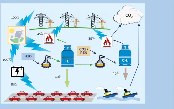
Figure 2 – Multiple ways to provide power and mobility services using electricity, H2 and SNG. Percentage
numbers are estimates of the full-chain energy efficiency. The source of CO2 for synthesis of SNG and the fate
of CO2 after SNG use are not specified.
35% 45% 100% 100% 15% 40% H2O CO2 + REN 80% CH4 H2
Figure 2 illustrates how the first two types of services (i. power and ii. mobility) can be provided using three different energy carriers (electricity, H2 and SNG, i.e. produced via CCU), powered by C-free RES.
The following remarks are worth emphasising:
• using renewable electricity to make a C-rich chemical fuel and converting the latter into power make sense for long-term storage and long-range transport of intermittent RES; the drop in efficiency is compensated by the provision of an additional service;
• while automobiles may be powered by any of the three energy carriers on the one hand, long-haul transport by ships or planes must rely on C-rich fuels for reasons of energy density. This is the case even when the energy efficiency of synthetic fuels based on CCU is as low as 15% and when the CO2 avoided may be limited when the source of carbon is fossil (see Section E below);
• going from electricity to chemical fuels, there is an increase of system
complexity and a concomitant expansion of required infrastructure, particularly in terms of CO2 conversion plants and fuel storage and transport infrastructure; • the technology chain yielding C-rich synthetic fuels requires a source of CO2
which is not needed in the other two cases, plus additional heat and power for the CO2 conversion process, which has to be provided by a carbon-free renewable energy source;
To place the analysis in Figure 2 in perspective, let us consider EU-28 final energy consumption for road transport. This was 3.5 PWh in 2015, with the EU-28 gross energy consumption using RES, of 2.5 PWh in the same year (Euroscope, 2017). If all road transport were electrified it would require 4.5 PWh RES (almost twice of the RES capacity installed and available in 2015). If it were based on green-H2, it would require 9 PWh RES (nearly four times that available). If all road transport were based on C-rich synthetic fuels, it would require 24 PWh RES (almost ten times the then available RES capacity, without considering the issue of intermittent availability of the C-free RES). However, the cost of such huge additional infrastructure would be partially compensated by the possibility of exploiting the existing infrastructure for fuel distribution.
E. FRAMEWORK FOR THE ASSESSMENT OF CCU POTENTIAL
OPPORTUNITIES
CCU technologies may offer a range of potential opportunities for European industries by supporting not only (i) climate change objectives, but also (ii) circular economic systems (O-economy, as opposed to linear economy, L-economy), (iii) energy security and deployment of RES (by providing RES storage alternatives), and (iv) evolution of CO2 capture systems (also required for CCS).
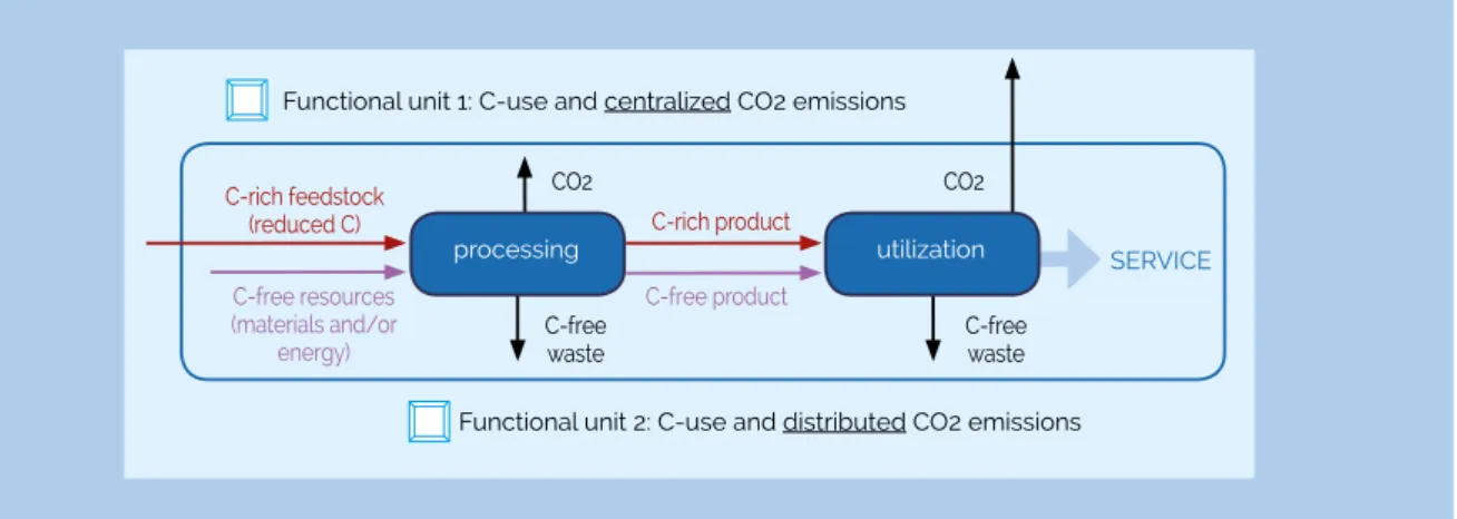
Figure 3 – Schematic description of two generic functional units receiving C-rich and C-free feedstock,
delivering a service and producing C-free waste and CO2.
The assessment of such opportunities calls for a CCU system analysis that goes beyond the energy efficiency comparison summarised in Section D, to focus on the C-bearing species and consider different ways of providing reduced Carbon-rich products, using them, and handling the CO2-associated waste either by disposal or reuse.
We have carried out a comprehensive analysis by considering: two generic functional units; a few process units; three sources of reduced carbon (fossil, synthetic and biogenic); a generic C-free RES; and CO2, both as a process stream and in the atmosphere. As shown in Figure 3, each functional unit utilises a reduced C-rich feedstock and a C-free resource to generate products that provide a service; in doing this both a C-free and a C-rich waste are generated. The different elements of each functional unit can be either coupled in space and time or completely decoupled, whereby the use of the C-rich feedstock (reduced carbon) and the generation of the C-rich waste (CO2) are separated by the specific product’s lifetime, tLIFE. The two types of functional unit differ in whether CO2 is formed in a centralised facility (power plant, industrial plant, incinerator with CO2 capture, large scale industrial boiler and so on), which can be equipped with a CO2 capture unit, or it is generated in a distributed manner (cars, buildings, airplanes, urea synthesis, incinerator without CO2 capture, and so on), where CO2 emission to the atmosphere cannot be avoided.
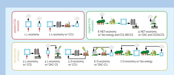
As shown in Figure 4, this results in nine possible technology chains, labelled 1 to 9, with schemes 1 and 7 consisting of two sub-schemes. These chains are grouped into categories according to their net CO2 emissions (positive, net-zero or negative), as determined by making a set of simplifying assumptions:
• the post-combustion CO2 capture rate is 100%;
• the yield and selectivity of CO2 conversion reactions are 100%; • the biomass treatment plant has 100% yield;
• use of biomass to generate bio-energy is carbon neutral; • CO2 conversion and DAC are powered by C-free RES.
C-free waste C-free product C-free resources (materials and/or energy) C-rich product C-rich feedstock (reduced C) C-free waste SERVICE CO2 CO2 processing utilization
Functional unit 1: C-use and centralized CO2 emissions
The schemes of the first category (red box, positive emissions) belong to the linear economy; the schemes of the second (yellow box, net-zero emissions) belong either to the linear or to the circular economy, and as far as the carbon atoms are concerned, there is neither a net input nor a net output of carbon atoms; the schemes in both categories deliver a processing or utilisation service as represented in Figure 3. The schemes of the third category (green box) generate negative emissions: CO2 goes
linearly from waste in the atmosphere to waste in a repository underground, while
delivering an environmental service, namely removal of CO2 from the atmosphere; scheme 8, BECCS, makes also bio-energy available, thus providing a second service. These schemes allow the conceptualisation of the carbon cycle within complex technology chains, thus providing a framework for the assessment and accounting of the climate benefits (or drawbacks) of a specific solution. Using the schemes in Figure 4, this could be performed in a spreadsheet as a precursor to more rigorous Life Cycle Analysis-based studies.
Figure 4 – Technology chains involving the functional units of Figure 2, and different combinations of technology
elements to deliver schemes causing positive CO2 emissions (red box), net-zero emissions (yellow box) and
negative emissions (green box); L-economy = linear economy, O-economy = circular economy.
Symbols used in the technology chain illustration of Figure 4 and their explanation.
nega tive C O2 emissions po sitive C O2 emissions ne t-zer o C O2 emissions 1. L-economy 3. L-economy
w/ CCS 4. L-economy w/ DAC-CS 5. O-economy w/ CCU 6. O-economy w/ DAC-CU 7. O-economy w/ bio-energy 8. NET-economy
w/ bio-energy and CCS: BECCS 9. NET-economy w/ DAC and CS:DACCS 2. L-economy w/ CCU
Functional unit 1: point source CO2 emissions (post-combustion CO2 capture possible)
Functional unit 2: distributed CO2 emissions (post-combustion CO2 capture not possible) Fossil (reduced) carbon Oxidized carbon (CO2) Synthetic (reduced) carbon Biogenic (reduced) carbon
Renewable energy source CO2 in the atmosphere Post-combustion CO2 capture (PCC)
Direct air capture of CO2 from the atmosphere (DAC) Underground CO2 storage
CO2 conversion plant, incl. electrolyzer for H2 Managed biomass growth
F. ANALYSIS OF TECHNOLOGY CHAINS
With reference to the technology chains illustrated in Figure 4, the following observations are worth making:
• Scheme 1 represents conventional (L-economy) uses of fossil fuels, with CO2 emissions that are either concentrated (scheme 1 left-hand side, with functional unit 1) or distributed (scheme 1 right-hand side, with functional unit 2).
• Schemes 3 and 4 couple the use of fossil carbon with CCS to avoid CO2 emissions; in scheme 3 point source emissions (power plants, industrial facilities, incinerators) are considered where post-combustion capture (PCC) can be applied, whereas in scheme 4 CO2 emissions are from distributed sources and direct air capture (DAC) has to be applied to extract CO2 from the atmosphere and make its storage possible (scheme 4 can be viewed as a combination of schemes 1 right-hand side and 9).
• Scheme 2 illustrates the “Carbon used twice” CCU concept; this is still an L-economy technology chain, where maximum 50% of the CO2 emissions associated to the two services provided (both functional units 1 and 2 are present in scheme 2) are avoided, thanks to the injection of RES into the CO2 conversion step.
• The presence of CCU in a technology chain is not sufficient to lead to an O-economy; this only occurs in schemes 5 and 6 (but not in scheme 2), where either CO2 is not emitted (thanks to PCC in scheme 5) or it is emitted and then captured back from the atmosphere (thanks to DAC in scheme 6).
• CCU is not a necessary element of an O-economy either: schemes 7, which are based on biomass and include no CCU, deliver bio-energy or biomass-based value-added chemicals, and belong to the O-economy: carbon recycling is made possible by the natural carbon cycle.
• Scheme 5 represents the long-term long-range storage of intermittent RES in C-rich synthetic fuels, which can be used (also intermittently when RES is not available) for power generation. Other storage possibilities, such as using batteries, pump-hydro, and C-free chemical fuels such as H2 and
ammonia, should in a context broader than that of this report be considered as alternatives (2).
• The production of C-rich chemicals and materials, which emit CO2 to the atmosphere at the end of their life, can be made emissions free in two ways, namely according to either scheme 4 or 6, based on the use of either CCS or CCU, respectively. In the former case the CO2 is sequestered underground, whereas in the latter it is kept indefinitely in a loop.
• The key difference between bioenergy plus CCS (BECCS) and DAC plus CCS (DACCS) is that besides enabling negative emissions, the former technology chain makes bio-energy available, whereas the latter requires RES to power the generation of negative emissions.
• When evaluating the impact of a new technology solution in terms of the four potential opportunities summarized at the beginning of Section E, the following steps should be made:
1 the whole technology chain to which the new technology solution belongs should be described and identified as one of the schemes illustrated in Figure 4; 2 such description should include the source of C-free RES, the source of CO2 and
of other chemicals needed, the product generated and its typical tLIFE;
3 accordingly, material and energy balances around the system boundaries defined in Figure 4 should be calculated, using the best estimates from the literature; 4 additionally, infrastructure needed and land use (for biomass growth and DAC)
associated to the scheme of interest should be estimated from the literature; 5 the current and projected scale of the new technology solution should be
estimated and the relevant assumptions articulated.
• Since some of the schemes in Figure 4, including all that involve CCU, require C-free RES, care must be taken in assuming that such RES is indeed CO2 emissions free. LCA analyses have shown that C-free RES can have a non-zero carbon footprint (3). Additionally, the carbon footprint of the current energy mix might be reduced more substantively if the RES utilised for CCU were alternatively used to replace other sources (4).
• Figure 4 clearly shows how various combinations of CO2 capture, recycling, and storage technologies can enable both O- and NET-economy schemes.
• A full LCA analysis is needed to support the conclusions of the preliminary assessment based on the simplified methodology described in the first bullet point of this list; this is also needed to determine how the possible CO2-emission benefits should be allocated to the different stakeholders involved in the complex technology chain selected (1).
G. REQUIRED INNOVATIONS
There are three major areas for innovation, where CCU systems are being looked at with increasing resolution.
1. Political boundary conditions
The system approach required to evaluate the technology chains illustrated in Figure 4 (including their CCU system elements as shown in Figure 1, with their complex and different scales in time and volumes) calls for a system of political measures, regulations and incentives equipped to look at the energy system in a holistic, co-ordinated and transparent manner.
2. Systemic aspects
With reference to Figure 4, it is clear that in terms of CO2 emissions, of efficiency in the use of RES (see Figure 2), and of infrastructure and costs, it is of paramount importance
services of different natures under evolving environmental, economic and socio-political constraints. This calls for a systemic approach to CCU as part of a truly sustainable energy system. There are many elements of such systemic approach that need crucial further development, including developing the awareness of such system dimensions among stakeholders (so as to overcome unproductive conflicts, e.g. between CCU-advocates and CCS-proponents), and defining clear and consistent system boundaries as well as reference datasets and assumptions.
3. Technical gaps in knowledge
With reference to Figure 1, the three core technical challenges of CCU subsystems are: • The collection and purification of CO2 from a variety of sources, where its
concentration is very different, namely from 400 ppm in air, to 5% to 14% in flue gases of fossil-fuel fired power plants, to about 40% or more in certain industrial streams. Developments in this area will be beneficial for a variety of technology chains shown in Figure 4 (see also Section F); research and development should address the energy efficiency and intermittent operation of capture processes, as well as CO2 purity after capture.
• The synthesis of “green” hydrogen via water splitting powered by RES, where breakthroughs are needed to make its scale-up technically and economically feasible. Note that “green” hydrogen is a prerequisite also for C-free synthetic fuels such as hydrogen itself and ammonia; hence scientific and technical progress in this area will be beneficial in a broader context than CCU alone.
• The reductive activation catalytic technologies for CO2 conversion to fuels and chemicals, where recent scientific progress in theoretical and experimental aspects opens up opportunities for coupled material and process development.
H. RECOMMENDATIONS FOR ACTION
We have concluded that there is compelling evidence of the need to tackle in a holistic and coordinated manner the science and technology of future defossilised energy systems and of the services that they will provide. By addressing such systems with a systemic approach, the challenges posed and opportunities offered by the CCU subsystems will be naturally highlighted and dealt with. We present the following action list for consideration:
1 Establish an EU technology platform on de-fossilised energy systems, which addresses points 1 and 2 in Section G.
2 Launch a top priority R&D effort on the science and technology enabling the deployment of the future defossilised energy system, including advanced energy storage and transport concepts (C-based or C-free) as well as the technical challenges described in point 3 of Section G.
3 Support the previous two action points by the creation of frameworks and funding schemes for the research, development, piloting and demonstration of the technologies mentioned above, both at the EU level and at the state level.
1. Preamble
The present document collects scientific evidence for answering the two main questions as formulated in the CCU Scoping paper received from the Group of Chief Scientific Advisors) and SAM Unit
• Under what circumstances CCU for production of fuels, chemicals and
materials can deliver climate benefits and what are their total climate mitigation potential in the mid- and long-run?
• How can the climate mitigation potential of CO2 incorporated in products such
as fuels, chemicals and materials be accounted for considering that the CO2
will remain bound for different periods of time and then may be released in the atmosphere?
These questions are fundamental to our understanding of the energy transition. It is now well recognised that the services that CCU can deliver within the whole energy system, including as a technology able to provide storage for RES, may be critical for the evolution of energy systems in the medium-term time horizon defined up to 2050. More recently, CCU occurs in the literature as an option for, in particular, the mitigation of unavoidable CO2 emission sources, e.g. aviation and shipping.
Withdrawal of fossil energy from the energy system is the top priority of the energy transition effort. The radical term “decarbonisation”, meaning that all carbon-containing energy vectors should be removed from the energy system, is unlikely to be realistic; there will always be applications in the entire energy system that require carbon atoms to be used (5) and hence demand the continued existence of carbon-containing energy carriers. This does not mean that their CO2 emissions can remain unaccounted for. A cyclic utilisation of carbon and hence a circular carbon economy (6) with no new fossil carbon entering the energy supply chain will be needed. To indicate the prerequisite of removing fossil energy from the energy system rather than all carbon atoms, we use the term “defossilisation” where adequate.
CCU is a flexibilisation measure (6, 7) in an energy system that is rich in intermittent Renewable Energy Sources (RES) and that integrates all sectors of energy consumption
Novel carbon capture and utilisation technologies: research
and climate aspects – SAPEA Working Group Technical
Report:
with a balanced distribution between electric and material energy carriers. The need for carbon (5) in any energy system is then met by a technical carbon cycle (6) of which CCU is one part. The transition to such a system may aim at retaining a maximum of existing technologies and at opting for a replacement of fossil material energy carriers wherever adequate by its synthetic analogue. Such an approach requires a large surplus of RES over an all-electric energy system due to still-inadequate storage capacity and inherent inefficiencies in energy conversion chains. It is clear that other flexibilisation options such as nuclear energy, bioenergy, batteries, some geothermal, thermal storage, storage of hydrogen and demand side management can and will contribute substantially to the stabilisation issue. Intelligent design of energy systems will consider complementarity of the various sources and their competition with CCU, but this is outside the scope of this report. The Working Group (WG) agrees that any CCU scheme using fossil energy sources is counterproductive and must be avoided. The WG further agrees that the application of RES in directly defossilising energy applications is of utmost priority (8).
The WG defines CCU as a series of interconnected technologies that collect CO2 (capture) either directly from the air (direct air capture DAC) or from concentrated point sources or indirectly from using biomass in processes that are assumed to have captured CO2 from the atmosphere in a sustainable way. The use of biomass implies land use issues, water consumption and material cycles for minerals and fertilisers that need assessment in terms of sustainability; the competition of biomass use with food requirements must be avoided. The WG assigns the applications of CCU to the categories “strategic” and “climate-relevant”. Strategic uses replace fossil carbon in chemical and material applications. Climate-relevant uses are large-scale applications where the saving of fossil carbon and the avoidance of CO2 are the drivers. Likewise, bulk transport and seasonal storage of RES are also climate-relevant applications. Although relevant from a technical perspective, the WG has decided to exclude non-carbon energy vectors, such as NH3, to focus on the questions posed.
In the CCU Scoping Paper, it was stated that the WG should abstain from considering uses of CO2 that do not change its chemical structure. Explicitly, uses in enhanced oil recovery (EOR) and applications where CO2 is used as working medium are excluded. The WG assumes that RES are used for all energy input into CCU. The WG was asked specifically to omit carbon capture and storage (CCS) from its deliberations. The analysis follows to a certain extent this request but occasionally has to refer to it to make clear that CCU and CCS are, despite their complementarity and similarities in designation, two measures with completely different (9) service functions in an energy system, which can be nonetheless analysed in a comparative manner.
The group discussed the reference frames for Life Cycle Analysis (LCA) studies. Despite examples of numerically precise LCA studies about CCU that are referred to in the main text, the WG concluded that numerical accuracy is not useful when making
predictions over timescales where technological progress and changing boundary conditions create large uncertainties in the set of assumptions required for LCA. This instrument is, however, most useful when looking at the needs for future technological developments or evaluating the climate mitigation effect of present CCU approaches and determining from there what critical developments will make CCU a valuable contribution to a sustainable energy system. In this way, our distinction of operational modes of CCU was accomplished and the requirement to use only renewable primary energy for CCU was identified. The WG considers the sum of all services that CCU can provide for the energy system of the future as valuable enough to go into a more detailed description of CCU functions. The request also mentions the need to take informed decisions for the funding of research and development activities by the EU. In order to provide insight into this aspect, the group indicates, in a broad way, where innovations are needed in order to effectively implement CCU should it be agreed that it is a valuable and useful tool for climate change mitigation.
Structure of the work
Chapter 2 introduces the concepts of the report and sets out a wider context of energy demand within Europe over geographical, temporal and societal scales.
Chapter 3 of the report defines the system boundaries that have to be considered when analysing different technology chains, which might include CCU or not, to provide the four types of services described in this chapter.
Chapter 4 provides technical information and specifications about the technologies that are the building blocks of the technology chains considered in this chapter as well as in Chapter 5.
Chapter 5 carries out a simplified system analysis of service delivery, based on the technical specifications reported in Section 4 and on the methods presented in Chapter 3. Chapter 6 presents innovation pathways related to the application of CCU in the context of the services discussed in this report.
Finally, Chapter 7 summarises the report and makes a final assessment of CCU potential in the context of climate mitigation. In that chapter, a matrix representation reported underneath will be used to qualitatively rank the different combinations of service (power, mobility, energy storage and products) and energy carrier, namely carbon-free electricity, hydrogen from renewables (green-hydrogen), synthetic fuels obtained by applying CCU, and current fossil fuels.
2. Introduction
2.1 CARBON DIOXIDE CAPTURE AND UTILISATION
CCU, CO2 Capture and Utilisation, is defined for the scope of this study as “those technologies that use CO2 as a feedstock and convert it into value-added products such as fuels chemicals or building materials”. Accordingly, when viewed from a system perspective, CCU is a system consisting of at least four steps:
1 Capture of CO2 from an industrial exhaust stream, or directly from air;
2 Conversion of CO2 to a carbon-rich (C-rich) chemical product (where in most cases the carbon atom is in a reduced state with respect to its fully oxidised state in the original CO2 molecule);
3 Utilisation of the C-rich product to deliver a service to society, e.g. by burning the fuel to provide propulsion;
4 Disposal of the carbon atom, either by disposing of the product as such (e.g. in landfill) or by disposing of the relevant decomposition products, typically CO2 again or another greenhouse gas such as methane.
Typically, step 2 is a chemical process (i) that is endothermic and endergonic, and (ii) that requires hydrogen (H2) as co-reactant (4, 10). Hence, CO2 conversion involves at least three elements:
1 harvesting of required C-free renewable energy (RES);
2 synthesis of green-H2 via water electrolysis powered by RES (a highly endothermic and endergonic reaction);
3 CO2 conversion via reaction with H2 (reactions that can be exo- or endo-thermic, exergonic or endergonic).
2.2 GENERAL CONSIDERATIONS
This concept of using CO2 either as a synthetic building block or as raw material for carbon atoms has a long tradition in chemistry. It was also recognised early on that the hydrogen source must be without a carbon footprint. This is enabled at present largely through electrocatalysis generating hydrogen from water splitting (11, 12). An alternative concept, direct electrochemical reduction of CO2, increases the energy efficiency of the chemical reduction by avoiding the combination and dissociation of H+ + e- (13). The concept of chemical CO2 activation created a large research community (7, 14-22) and brought about a large scientific literature.
The seminal paper (23) of Lewis coined the term “artificial photosynthesis” and introduced the concept of CO2 as raw material for chemical energy conversion and storage. From a technical-industrial viewpoint the use of CCU (although not a known term at the time) was advocated by Asinger (24) and made famous through the work of Olah (25, 26). These concepts mainly considered step 2 as defined above, but with the different goal of replacing oil as liquid fuel and not with a CO2 mitigation service as prime motivation.
The question about the quantitative CO2 mitigation potential was less relevant for energy system researchers, and is usually discussed in dimensions of the production capacities of the chemical industry (10). This ranges to a maximum 100 Mt of the carbon containing product, with the exceptions of polyethylene and urea (27) being above that line.
This largely undisputed results of research in the chemistry field with a relatively short-term application horizon within the chemical industry (16, 18) clashes with the views of energy system research. This is documented impressively in a Faraday Discussion meeting held in 2016 (28-30).
Here, the emphasis is on the CO2 mitigation potential of a technology under discussion. In the present transitory situation, when we are moving away from fossil sources but do not have vast amounts of RES available, it is critical to prioritise the use of RES according to its CO2 reduction potential. In other words, measures requiring high specific RES input for a given CO2 saving should not be prioritised against measures that save CO2 for less RES input. The present work will critically evaluate this aspect (4, 10) particularly as it is often ignored when CCU is discussed (18) in the chemical literature. In this discussion, the energetic efficiency of a measure serves as a quantitative descriptor. CCU technologies have long conversion chains (steps) and this leads to poor energetic efficiency. The process efficiency of a chain of chemical energy conversion (electrons to hydrogen, 0.70, and hydrogen to molecules, 0.70) and reutilisation (0.35) of the primary RES amounts with present technologies to an order of magnitude efficiency of 15% of final use energy with respect to primary RES. The heated debate over this aspect leads to quotes like: “Producing a liquid fuel via
hydrogenation of CO2 and then using this to run an internal combustion vehicle is a
monstrous thermodynamic crime” (28).
The thermodynamic efficiency of an element in the energy system is a valid and important descriptor but by no means the only one of relevance. It is widely accepted that future energy systems with a high abundance of stochastic RES as a primary energy source will be much more integrated between the individual elements (sectors), and will be more complex, as a whole multitude of energy options is required to match energy requirements (31) with the volatile primary source. CCU as defined above is seen as an important technology family. The quote “Which is the bigger crime? Converting curtailed renewable energy into hydrocarbon fuels that can be stored long term, albeit with thermodynamic penalties, or paying subsidies to renewable energy producers to curtail supply of electricity that can be converted into chemicals
to avoid the use of new fossil carbon in the form of petrochemicals? Surely CCU is just
an example of resource efficiency, maximising productivity while reducing waste.” (28)
underlines the need to look closer into the issue. These divergent views arise also because the level of aggregation of arguments and analyses is vastly different in the literature ranging from individual plants (32) and facilities to regional energy systems (33-35) up to the global level (36). To address the complexity challenge, the appropriate methodology is to define a proper frame of analysis of the CCU contribution to an energy system; define timescales and the evolutionary state of an energy system; and introduce the concept of service functions that an element has within the energy system. This premise will be followed in the main body of the work.
2.3 ASSESSMENT OF THE LITERATURE
The scientific literature on the term “CCU” is still relatively limited. In a search for the acronym, the term begins to occur around 2010 in the literature and cannot be found easily as multiple meanings are associated with the acronym (in medicine, biology, computer science, electrical engineering). An early mention is found in the work associated with a review discussing ionic liquids as adsorbents for CO2 that could immediately be activated by electrochemistry (37, 38).
In 2009 a comprehensive review was published (39) comparing CCU in the present definition with CCS stating that substantial potential was in the CCU approach. A recent review on the industrial options (6) of CCS and CCU comes to the conclusion that both options are technologically mature but require substantial regulatory incentives to achieve sizeable CO2 reduction.
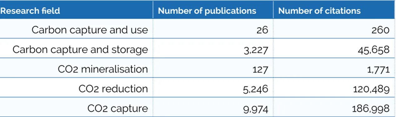
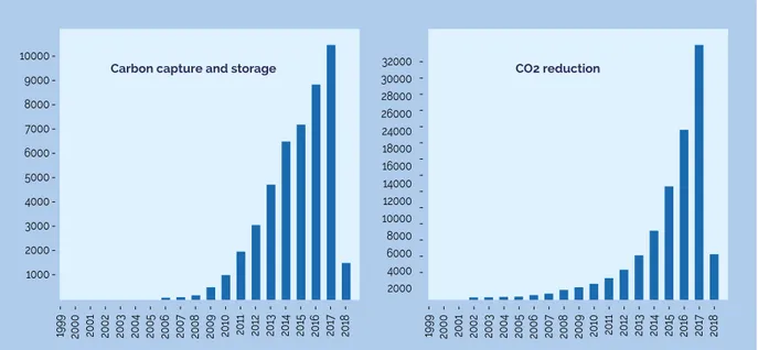
Table 2.1 reports the results of a search query on the Web of Science (WoS) database, for the number of publications and citations relevant to this report.
Research field Number of publications Number of citations
Carbon capture and use 26 260
Carbon capture and storage 3,227 45,658
CO2 mineralisation 127 1,771
CO2 reduction 5,246 120,489
CO2 capture 9,974 186,998
Table 2.1: Bibliometric indicators for selected relevant research fields.
The queries were filtered such that environmental and biology papers are excluded to focus on the present topic. Despite some arbitrariness in such filtering, the trends occurring from the table are obvious. The first three entries deal with subjects that were barely researched before 2010 whereas the two latter entries have a solid research history of over 50 years. All of the topics exhibit massive growth rates both in publications and citations as exemplified in Figure 2.1.
Figure 2.1: Citations in research fields by year. Source: Web of Science
It follows that the term CCU in the energy context is rather new and not yet widely communicated. The concept of CCU as outlined above is, however well established in the scientific literature. This may explain why the role of CCU as designated with this term is not prominently found in the broader climate change literature. The options for synthetic chemistry and for material synthesis are well discussed in the literature (7, 16-19, 22, 40-44) opening multiple opportunities with, however, limited CO2 reduction potential in the dimensional framework of climate change. The concept of services connected with CCU other than reducing CO2 is only barely acknowledged until now. One key challenge in finding reliable quantitative data on potentials and development stages is that very few CCU applications exist at scales suitable for deriving experimental observations. A vast portion of the literature deals with hypothetical system design concepts and uses data from existing component technology. This is the only serious method possible today as the industrial observations are still so rare. If the trends of scientific activity as seen in Figure 2.1 continue, it is likely that multiple improved and materials and novel system design concepts will emerge (23, 45). This will substantially change the view with which one judges the potentials and efficiencies. Great care must thus be applied when decisions about the usefulness of CCU options are based upon “quantitative” statements from the literature that cannot account for the true development potential. Two critical factors in evaluating the forecast and scenario results should be taken into account:
• What are the timescales involved?
• How are the energetic efficiencies rated in the work under consideration?
A general observation from reading the literature is that many authors are unclear about the dimensional scales at which their results or proposals integrate in the energy system. CO2 mitigation is a “teraton challenge” (39) and yet many critical challenges 10000 9000 8000 7000 6000 5000 4000 3000 2000 1000 -32000 30000 28000 26000 24000 18000 16000 14000 12000 10000 8000 6000 4000 2000
-Carbon capture and storage CO2 reduction
1999 2000 2001 2002 2003 2004 2005 2006 200 7 2008 2009 2010 2011 2012 2013 2014 2015 2016 201 7 2018 1999 2000 2001 2002 2003 2004 2005 2006 200 7 2008 2009 2010 2011 2012 2013 2014 2015 2016 201 7 2018 - - -
-exist in the sustainable energy system at mass scales many orders of magnitude smaller. This multi-dimensionality of the CCU technology is seen as one of the reasons for the passionate debate in the science community, together with a frequent fixation on uni-dimensional performance indicators that do not adequately reflect the system requirements (technical, environmental, regulatory, societal) of energy technologies.
2.4 DATA ABOUT ENERGY AND EMISSIONS
In 2016, Europe (EU 28) used a total of ~13,000 TWh equivalents (gross inland consumption). From Figure 2.2 it occurs that the amount varies in time over the short period in the figure more (7%) than the underlying weak long-term trend (2.5% reduction in 25 years) to lower values. The variations in Figure 2.2 indicate the care that has to be taken in interpreting short-term trends of such highly aggregated data. The large absolute amount gives an impression about the challenge faced to make the energy system sustainable.
Figure 2.2: Total energy consumption of EU 28 in TWh. Source: Eurostat (2017)
The difference between gross energy consumption and final energy consumption (in 2015 18,945 TWh vs 12,606 TWh) amounting in 2015 to 6,339 TWh or 50% of the final energy consumption is the aggregated sum of energy losses. This value marks the hypothetical upper limit of energy savings that is achievable through an idealised 100% energy-efficient replacement of fossil by renewable energy without changing the use pattern of energy.
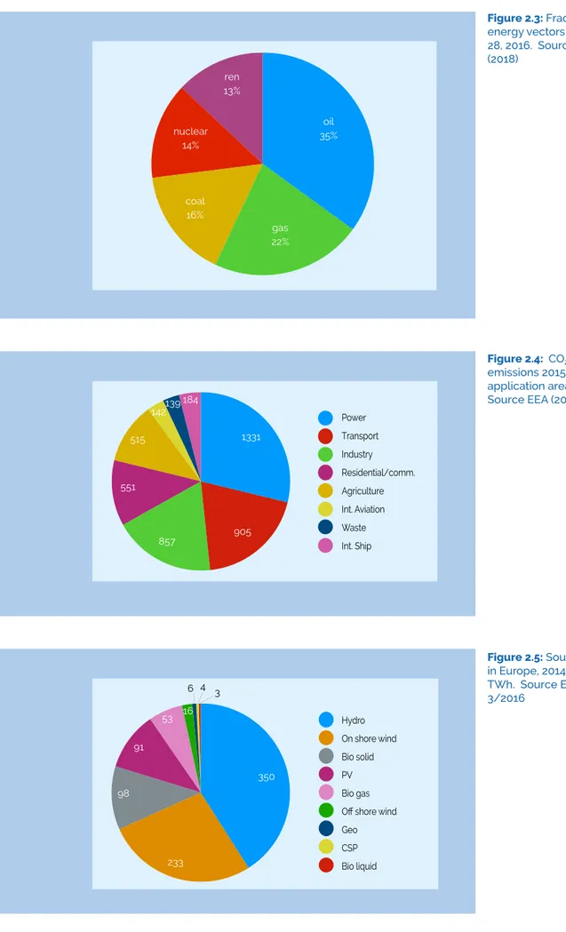
Figure 2.3 displays the fractions of energy vectors from which final energy needs currently originate. 72.5% of these vectors are still fossil in origin. 1,128 TWh equivalent of these energy vectors are used as feedstock for 97 MToe material, of which 84.5% are oil-based. This number designates the lower value of carbon utilisation that cannot be electrified. It amounts to roughly 10% of the final energy consumption. The energy import dependency in Europe is almost constant and reaches 54% for all fossil energy vectors, and 88% energy dependency for oil (all data from Eurostat (2018)).
21000 20250 19500 18750 18000 -2010 2011 2012 2013 2014 2015 2016 - - - -E nergy C onsumtion ( TWh)
ren 13% oil 35% gas 22% coal 16% nuclear 14% Figure 2.3: Fractions of
energy vectors in the EU 28, 2016. Source Eurostat (2018) 1331 905 857 551 515 142139 184 Power Transport Industry Residential/comm. Agriculture Int. Aviation Waste Int. Ship Figure 2.4: CO2 emissions 2015 in Mt from application areas, 2015. Source EEA (2017).
Figure 2.5: Sources of RES
in Europe, 2014. Values in TWh. Source EEA report 3/2016 350 233 98 91 53 16 3 4 6 Hydro On shore wind Bio solid PV Bio gas Off shore wind Geo CSP Bio liquid
Using the fossil energy vectors generates a total of 4,574 Mt CO2 emissions in the EU. The distribution according to energy applications is shown in Figure 2.4.
The expected general trend, driven by macro trends of globalisation, energy efficiency, and renewable electricity installation at scale, is that, while all transportation applications will grow in emissions, power and industry will reduce their emissions. Any more detailed analysis is complex as the aggregation removes largely the connection between detailed source information and its temporal evolution.
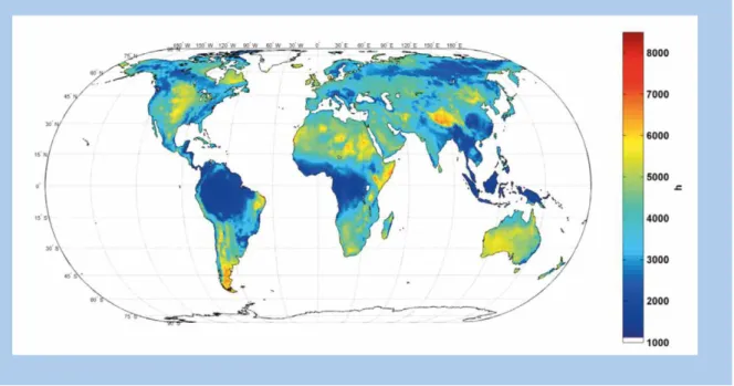
The present work defines “climate relevance” for CCU as an EU-wide reduction of CO2 emissions of 100 MT per annum. This is a humble contribution to climate mitigation. Figure 2.5 illustrates the availability of different forms of renewable resources. A substantial growth rate of installations should increase these values across the board, but from the recent trends in investments in the EU, this may not occur as quickly as often assumed. The leading role of Europe in the world for RES investment has now been ceded to China. The largest fraction of the 854 TWh of RES produced in Europe in 2014 was hydropower (with a low growth potential) followed by wind (with a much higher growth potential) and solar PV (with an even larger growth potential).
The total climate mitigation through avoided CO2 emissions in Europe of all these RES amounted in 2015 to 447 MT , (assuming average specific emissions of 0.455 kgCO2/ kWhe (46)of which Germany contributed -125.7 MT, Italy -49.7 MT, the UK -50.0 MT and Spain -37.8 MT. Comparison to the total emissions of 4,574 MT (in 2015) reveals that all RES avoided almost 10% the CO2 emissions (47).
2.5 TIME SCALE OF DEPLOYMENT
CCU is not an existing family of technologies today. Demonstrators exist for elements of that technology and other elements exist as operating units within the conventional chemical and energy technology portfolio (16, 32). Their combination and interface to the energy system in any sizeable dimension does not exist today. Claims (6) about the technology readiness from an industrial perspective require verification. This means that we have no experience with any CCU process integrated into an existing energy system at scale. What we do have is ample experience with elements of CCU processes, such as catalytic reactions.
Considering these factors, together with the uncertainty over regulatory and economical boundary conditions, time scales of implementing CCU measures at the level of grid-relevant demonstrations or roll-out on the system level will undoubtedly be long. A prototypical example is the gas-to-liquids (GTL) process (48) developed by Shell. In 1972, the view was that fuels from other sources than oil would be necessary, and intense basic research commenced. In 1983, the first demonstration plant to convert gas to petroleum was built, using the
well-established Fischer-Tropsch technology. In 1993, the first commercial plant began operation in Malaysia and in 2011 the mega large-scale plant in Qatar began operation. Only after 40 years of intense research and development, including many academic and industrial sub-projects, and within a suitable market environment, was the time mature for one truly world-scale commercial implementation. In common with present-day CCU considerations, all unit operations were in principle known and technological ready but never at such large scale or in such complex integrated configurations.
In CCU the time from concept to demonstrator and grid-scale implementation is likely to be of a similar time scale (at least one decade). We may benefit from more technological experience and more powerful design tools than in the past, but breakthrough innovations are still required, particularly in the challenge of dynamical technical operation of chemical processes. Reduced full load hour (FLH) operations may require entirely new business models in the production of chemicals. By 2035 we may have realistic and scaled demonstrators working (in “real laboratories”), which provide sufficient insight and data to design technically and economically world-scale CCU operations. If they were operational as demonstrators by 2050 and their roll out in large units began then, their development should be viewed as fast. Fast-track innovations with small and decentralised units may be ready in 2035 but then the socio-economic and regulatory boundary conditions need to be favourable in time suitable to incentivise early investors.
From the GTL example one learns that not just one product but a whole suite of synthetic fuels for mobility was derived. One may envisage thus in climate-relevant CCU technologies that the timeline may not be dictated by the need of a single target (CO2 abatement) but by the needs created from several services. Product users, price evolutions, regulatory conditions, socio-political events and unexpected breakthroughs in science and technology may accelerate or hinder the development. Multi-parameter evaluations for timescales and the underlying drivers will be needed. An example of such a multi-parameter situation is the evolution of mobility (49, 50) in the world.
The development of strategic CCU in chemical production (51) may be much faster. Early developments (for instance polyurethane products from Covestro) exist today in commercial scale and are starting to branch out in new application fields. Here it is critical that stakeholders are convinced (16) that such CCU applications add value and can stabilise or even promote the growth of the European chemical industry. It may well be seen that in 2035 a whole range of chemical strategic applications of CCU will be in place. It is noted however, that such predictions have been made before (43) with little realisation until today. This may be due to the unfavourable external conditions for making CO2 a realistic feedstock in chemical industry at large scale and beyond the classical applications of urea and methanol synthesis.
A driver to accelerate CCU implementation may be the need to transport RES with the same technologies as we transport fossil energies (as liquids or compressed gas) throughout Europe and the world. It is inconceivable that sustainable energy systems will be able to only use local supplies of RES. Here, CCU has a broad and strategic potential as part of the ‘Power2X’ technology family. This may drive development such that in 2050 we have operating systems at world-scale. The development to supply Japan (52) with hydrogen through such technologies is one example, with the stated aims of the “liquid sunshine” (53) project in China being another. These are instructive examples of how other economies in the world are addressing the CCU debate. The Chinese large-scale project is relevant for the present discussion in the EU as it plans to use CCU deliberately in a staged way to bring clean energy carriers as fast as possible into cities. In the first stage coal will be the carbon and energy source for the production of methanol energy carrier, so as to demonstrate the technologies. According to the proponent plans, gradual addition of RES makes it “clean” and full CCU with biomass makes it sustainable. The project is planned over half a century on a scale larger than 100 Mt methanol per year.
The argument that CCU may compete for RES on a large scale, at times where RES is required to more directly substitute fossil power is contradicted by the timescale foreseen for CCU systems. All EU planning for the roll-out of RES in the power sector foresees a level of above 50% RES in the power system by 2050. At this level storage and transport of RES will be critical and all the flexibilisation measures will have to be in place. CCU is expected to be then a complementary technology (at least locally) rather than a competitor for RES. At the present level of RES penetration this would not be the case and thus high levels of RES are unconditionally a pre-requisite for CCU implementation beyond demonstrators. The European situation is in this respect different from that in China where this pre-condition is not relevant in considering the need for minimising local emissions in cities. Consequently, it should be recognised that such development as well as similar ones in other parts of the world create opportunities but also threats for the European export industry for infrastructure technologies.
In summary, the time at which CCU may become a climate-relevant contribution in a sustainable energy system is likely to be after the time when the available RES is developed sufficiently to replace fossil power applications. In smaller applications such as in the raw material industry where regulatory measures for mitigation are crucial, or in de-centralised applications, CCU may begin to operate earlier. The target year of 2050 is regarded as reasonable for CCU proponents as a flexibility option against temporal surplus RES, which may begin to play a role when other flexibility options might not appropriately deliver defossilised energy into non-electrifiable sectors of the system (we tentatively estimate the time horizon of this after about 2035). These applications would not endanger the prime target of using RES to replace fossil energy as much as possible in power and heat generation.