G. Auger, P. Bin´etruy and E. Plagnol, eds. c
!2013 Astronomical Society of the Pacific
PETER: A Hardware Simulator for the Test Mass-GRS System of
LISA Pathfinder
Lorenzo Marconi,1,2Ruggero Stanga,1,2Massimo Bassan,3,4Fabrizio De Marchi,3,4
Giuseppe Pucacco,3,4Massimo Visco,4,5Luciano Di Fiore,6Rosario De Rosa,6,7Fabio
Garufi6,7
1Dipartimento di Fisica - Universit`a degli Studi di Firenze, Firenze, Italy 2INFN Sezione di Firenze - Firenze, Italy
3Dipartimento di Fisica - Universit`a di Roma Tor Vergata, Roma, Italy 4INFN Sezione di Roma 2 - Roma, Italy
5Istituto di Astrofisica e Planetologia Spaziali - INAF, Roma, Italy 6INFN Sezione di Napoli - Napoli, Italy
7Dipartimenti di Fisica - Universit`a di Napoli, Napoli, Italy
Abstract. Each LISA PathFinder test mass (TM) will be sensitive to forces along all its 6 Degrees of Freedom (DoFs). Extensive ground testing is required in order to evaluate the influence of cross-talks from the read-out and actuator channels. In the INFN laboratory of Firenze we have developed a facility for a good representation of the free fall conditions of the TM on flight. A hollow replica of a TM hanging from a double torsion pendulum can move inside a Gravitational Reference Sensor (GRS) with quasi free fall condition on two Dofs, in the frequency band (0.1 ÷ 100)mHz. On both DoFs, the target residual accelerations (yet to be achieved) at the low end frequency range are ≤ 3 10−13ms−2, limited by the thermal noise of the fibres. At higher frequencies, the sensitivity is limited by the readout noise of the readout, a replica of the flight electronics. After a long commissioning, we are now in operating conditions, and can carry out a series of experiments to better qualify the interaction between TM and GRS. In this paper we will show some significant qualification measurements and a first scientific measurements, i.e. the measurement and compensation of the DC bias in the GRS using two independent channels, as well as a measurement of the residual acceleration of the translational DoF, with the feedback loop closed on the rotational one, and viceversa.
1.
Introduction
One of the main features of the LISA mission is the free-fall operation mode, that implies iso-lation of the test masses (TMs) from all disturbances. To meet the LISA requirement, the residual acceleration noise in the free-falling frame of the test mass must be smaller than 3 · 10−15m/(s2Hz1/2)@1mHz (Vitale et al. 2002). Among the perturbing sources, special
at-tention has to be given to the interaction with the electrostatic sensing and actuation system, that could introduce an unwanted coupling between test mass and spacecraft. The capacitive sensing and actuation device, called the Gravitational Reference System (GRS) (Dolesi et al. 2003), provides the relative position input to the control loop that is closed on micro-thrusters, that force the spacecraft to follow the test-mass. Extensive ground testing is required to study the residual weak forces that may couple the Yest Mass to the GRS. Up to now, excellent re-sults in the measurement and reduction of residual acceleration have been obtained with single
2.
The status of the PETER apparatus
In the last few years we have built and now operate a double torsional pendulum, nicknamed PETER (PEndulum Translational and Rotational) (Marconi et al. 2012). We use two W torsion fibres to suspend a hollow, cubic test mass, figure 1: the lower, ϕbfibre allows the test mass
to be quasi free in rotation around its symmetry vertical axis. This fibre hangs from the tip
Figure 1. The scheme of PETER apparatus.
of the arm of a crossbar that is, in turn, suspended to an upper, ϕa fibre: the torsion of this
upper fibre allows quasi free motion of the test mass along a short (few mm) arc of a d = 30cm diameter circumference: for all practical purposes, this can be considered a translational motion: x = d · ϕa. Dummy balancing loads hang from three other arms of the crossbar. The
sensitivity goal for this apparatus, limited by the mechanical setup and the electronics noise is ≤10−13ms−2/Hz1/2
around 1mHz (on each DoF), namely 1 order of magnitude worse than the LISA PF goal along the sensitivity axis. Further details can be found in (Stanga et al. 2009).
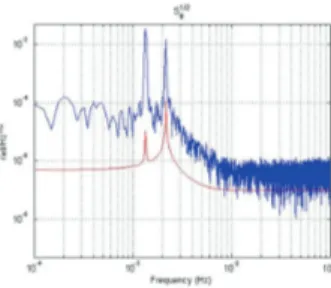
The cubic TM with 46mm side, the capacitive sensors in Mo and SHAPAL and the capac-itive read out electronics, replica of the flight model, well match (apart for the mass of the TM, here a hollow Al cube for about 106 g) the set-up of the LISA-Pathfinder inertial sensor. The apparatus is also equipped with an Optical Read Out (ORO) system (Acernese et al. 2005) that can provide an independent measurement of the test mass position along the 2 soft DoFs. ORO is useful both for diagnostic purposes and for cross-correlating two independent (optical and electrostatic) readouts, a technique that can significantly reduce the readout noise. In figure 2 and 3 we show the amplitude spectral density of the angular and linear displacements, com-pared to their intrinsic limit set by fluctuation-dissipation theorem. One can wonder what level of acceleration noise would these measured values represent on a real LISA Pathfinder TM: we can convert them by considering an arm length of 0.02m (i.e. the sensing electrodes separation), or 0.15m (i.e. the length of the crossbar arm) respectively, and a load mass of 2kg, obtaining the results shown in figure (4, 7). It can be seen that, at high frequencies we are limited by the electronics noise while at low frequencies we are a factor ∼ 50 above the thermal noise limit
Figure 2. Angular noise spectrum for ϕbDoF.
Figure 3. Translational noise spec-trum for x DoF.
of the suspension fibre for the ϕb DoF and a factor ∼ 100 above the thermal noise limit of the
suspension fibre for the x DoF. We are presently investigating the origin of the excess noise.
Figure 4. Acceleration noise spec-trum for ϕbDoF.
Figure 5. Acceleration noise spec-trum for x DoF.
3.
DC bias measurement
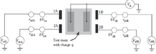
We have performed a preliminary electrostatics characterization of the GRS. The procedure we applied extends to 2 DoF that outlined in (Weber et al. 2007). The spurious DC potentials due to patch fields on the sensor surfaces couple to the test mass charge fluctuations and can be a relevant noise source on force for LISA and LISA PF. A modulating voltage applied to the TM couples to these potentials and produces an a.c. force and torque:
F1ωz = − 4Cz Ctot Vzsin(ωzt) ! ∂Cx ∂x " ∆x, (1) N1ωz = − 4Cz Ctot Vzsin(ωzt) ! ∂Cx ∂ϕb " ∆ϕb. (2)
where ∆xand ∆ϕbare linear combinations of the stray potentials on the x electrodes (Weber et al.
2007). We assumed here the TM to be centered in the GRS and the the potentials to be uniform on each electrode. With a modulated bias Vz = 6Vp−pat ωz/2π = 3mHz, we measured force
and torque and, inverting equations (1),(2) we consistently got the values of ∆x = 320 ± 5mV
e ∆ϕb = 170 ± 8mV. We can now these voltages as a bias to compensate these stray potentials
so as to minimize either the force or the torque noise on the TM: table 1 shows that applying a bias ±∆xminimizes the residual potential that couple to force, but not to torque, and viceversa
for an applied ±∆ϕb. There exists, however a combination of biases that reduces both residual
charge are denoted δVi, vniand q. In the main measurement described in the text, a
modulated bias V∆is applied to the test mass via the z electrodes. Actuation voltages
Vaican be applied to compensate δVi, as detailed in (Weber et al. 2007).
V
COMP ∆4x ∆ϕb 4 ∆x 4+
∆ϕb 4∆
xRES IDU AL0.005V
0.300V
−0.002V
∆
ϕb RES IDU AL0.175V
0.011V
0.016V
Table 1. Values of ∆xe ∆ϕbobtained with different compensation schemes.
When the patch potentials are compensated, the remaining electrostatic coupling is due to the net charge of the TM. We then apply both the compensating bias (either for force or torque) and a modulating potential VMat a frequency ωM/2π to induce:
FωM = −4VMsin(ωMt) ! ∂Cx ∂x " q Ctot ; NωM = −4VMsin(ωMt) ! ∂Cx ∂ϕb " q Ctot (3) With a measurement of either force or torque we find the residual charge on the TM. We got two independent values: q = 6.4 10−7e
when compensating on the x DoF, and q = 4.7 10−7e
on the ϕ DoF: these values are similar, and comparable with those reported in (Antonucci et al. 2011).
4.
Behaviour under feedback control
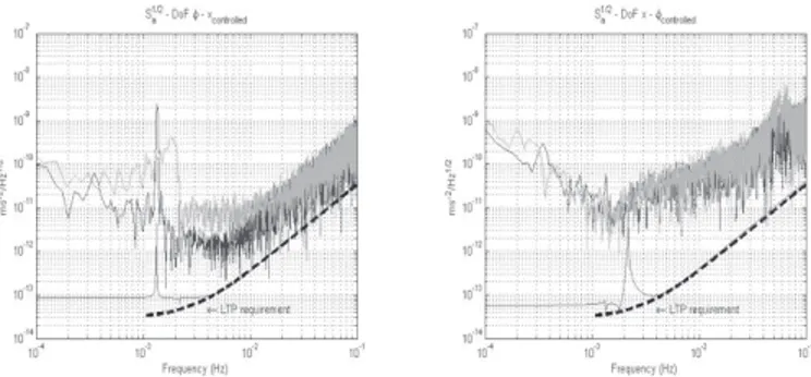
One of the main motivation of the PETER experiment is its ability to operate with one DoF in free motion while the other kept to a fiducial position by feedback control. This test will shed light on the extra noise from cross-talk that the LISA-PF TM will have to stand along its sensitive axis, as position control on the other DoFs is unavoidable. We have proven this ability and show in figure 7 some preliminary measurements: although the system is still too noisy to extract any significant information, we do see that some cross coupling is present, and we shall try to minimize it.
5.
Conclusions
We satisfactorily tested the functionality of our double torsion pendulum. Much work is ahead in order to create a facility for ’free motion’ tests: lowering the noise level, down to the limit set by thermal noise in the fibers, is our foremost priority. Additional and more precise measure-ments will be carried out, and correlation analysis with enviromental monitor channels (seismic, thermal and magnetic above all) will be performed. Future hardware improvements will include the installation of a tip-tilt alignement system, to better center TM in the GRS; full implemen-tation of the optical read out system; a more efficient thermal stabilization of the apparatus.
Figure 7. Behaviour of the double pendulum in controlled mode: We show the noise level of each DoF ( ϕb DoF on the left, x on the right) both in free motion
(black) and when the other DoF is feedback controlled (gray).The noise spectral amplitudes are converted to linear acceleration, as in fig 3, 4.
References
Acernese, F., et al. 2005, Class. and Quant. Grav. 22, S279 Antonucci, F., et al. 2011, Class. and Quant. Grav. 28, 094002 Cavalleri, A., et al. 2009, Class. and Quant. Grav. 26, 094012 Dolesi, R., et al. 2003, Class. and Quant. Grav. 20, S99 Hoyle, C. D., et al. 2003, Proc. Marcel Grossman Meeting Hueller, M., et al. 2002, Class. and Quant. Grav. 19, 1757 Marconi, L., et al. 2012, J. Phys. Conf. Series
Stanga, R., et al. 2009, J. Phys. Conf. Series 154, 012032 Tu, H. B., et al. 2010, Class. and Quant. Grav. 27, 205016 Vitale, S., et al. 2002, Physics Letters B 110, 210
Weber, W. J., et al. 2007, Advances in Space Research 39, 213 Zhou, Z. B., et al. 2010, Class. and Quant. Grav. 27, 175012