PARAMETRICAL ANALYSIS AND DIGITAL FABRICATION OF THIN SHELL
STRUCTURES: THE IMPACT OF CONSTRUCTION TECHNIQUE ON THE
RESULTING GEOMETRY OF THE GAUSSIAN VAULTS OF ELADIO DIESTE
F. C. Melachos1, W. Florio1, L. Rossato 2, M. Balzani 2,
1 Universidade Presbiteriana Mackenzie, R. da Consolação 930, 01302-000 Sao Paulo, Brazil - [email protected]; [email protected]
2 University of Ferrara, Department of Architecture, Via Quartieri 8, 44121 Ferrara, Italy, (luca.rossato, marcello.balzani)@unife.it
Comission II
KEY WORDS: Gaussian Vaults, Eladio Dieste, Geometry, Constructive Techniques, Parametric Modelling, Digital Fabrication
ABSTRACT:
The objective of this article is to analyze the state-of-art regarding the construction process of the Gaussian Vaults of the Uruguayan civil engineer Eladio Dieste and to identify the elements that underlie the relationship between the constructive techniques and procedures within this specific structural typology and its resulting geometry. As complementary objectives, this research aims for the identification of the gaps in the registry of such constructive procedures. The essay focuses on the geometry of the Gaussian Vaults designed and built by Dieste, in a way that these rigid structural surfaces’ geometry had their original construction drawings redrawn and analyzed from the perspective of its construction technique by means of the Parametrical Modelling and Digital Fabrication of case studies.
1. INTRODUCTION
The central objective of this paper is to verify and identify points of convergence between Eladio Dieste’s construction technique and the resulting geometry of the Gaussian Vaults. In order to do so, this paper is structured in the following sections: “1. INTRODUCTION”, where the research’s structure is laid out; the section “2. RELATED WORKS”, where the state-of-the-art relating this research topics are synthesized, section “3 DEVELOPED METODOLOGY”, where the research’s process will be laid out in order to make feasible the extraction of knowledge from the resulting data, and section “4 CONCLUSIONS”, where there were drawn some reflections upon the results in order to organize these thoughts and guide future reflections.
In order to proceed, it is important to define and explore the fundamental concepts within this research. Thin shell structures are rigid surface structures, that as according to Bechthold (2008) are rigid structural surfaces that derive their stiffness from curvature, as opposed to the folded-plates, that derive their stiffness folding.
Schodek (2014) established a consolidated taxonomy of structural systems in terms of geometry and principal physical characteristics. Eladio Dieste’s Gaussian Vaults, the object of study of this paper, are not mentioned by Schodek (2014), but the taxonomy system’s interpretation points out that the Gaussian Vaults could be interpreted as rigid structural surfaces
In Torrecillas (1996), Dieste himself defines this structural typology (Figure 1) by the following 5 design guidelines: 1. Structured in reinforced brickwork;
2. Use of the catenary as formal directrix, in a way as to maximize compression;
3. Self-weight stresses are independent from its cross-section; 4. The steel operates as an elastic unit before concentrated
loads;
5. The retrieval of the formwork does not demand the complete drying of the mortar.
Figure 1: Gaussian Vaults of the CEASA Market, in Porto Alegre, designed and built by Eladio Dieste between 1969 and 1972.
Eladio Dieste was deemed a structural artist by Ochsendorf (2004), due to the fact that he developed works of art whilst pursuing economy and structural efficiency. Anderson (2004) establishes that Dieste created a new structural typology, the Gaussian Vaults, and established new design and construction procedures for the reinforced masonry construction technique. Yet, being Latin American, his original contributions to architectural technology are not present in the Eurocentric established 20th century modern architecture anthologies. As shall be seen in the following section, “2.RELATED WORKS”, the consultation of academic indexers such as Web-of-Science (2018) and Avery Index (2018) has not revealed a full comprehension of construction and design process of this specific structural typology.
In order to consolidate the methodological procedures of this paper is also important to establish the definition of the concepts of parametric modelling and digital fabrication. According to Monedero (2000), Gross and Goldschmidt (2008), Hudson (2010)
The International Archives of the Photogrammetry, Remote Sensing and Spatial Information Sciences, Volume XLII-2/W9, 2019 8th Intl. Workshop 3D-ARCH “3D Virtual Reconstruction and Visualization of Complex Architectures”, 6–8 February 2019, Bergamo, Italy
and Woodburry (2010), parametric modelling (PM) can be defined as the modeling of a given geometry through the definition of a set of rules or parameters. It is based on the logic of the associative relationships and of the dependency amongst their objects and the relationship amongst components and the whole, where simple variations generate a family of shapes. The usage of PM in this research goes hand in hand with the concept of Digital Fabrication (DF) of Seely (2000), where it is defined as a group of processes aided by different computational technologies that manipulate or deform different materials. Sass and Oxman (2006) also state that the different strategies within DF enhance the comprehension of the tectonic of the form and the perception of architectural space.
The methodology undertook for this paper consists of the analysis of a case study by means of the scrutiny of its original drawings; their redrawing, to foster their understanding and establish a drawing pattern; their parametric modelling, in order to grasp their complex geometry with precision; and the digital fabrication, in order to potentialize the analysis such as the visualization of small constructive details. This process is fully detailed with its respective technical specifications on the section “3 DEVELOPED METHODOLOGY”. The previous parametric modelling of complex geometry undertook in the writings of Florio (2011) was the basis for the implementation of the modelling procedure in this paper.
In the final section “4 CONCLUSIONS”, the knowledge extracted from the section “3 DEVELOPED METHODOLOGY” is laid out and analyzed critically in an objective manner. As a complementary objective of this closing section, it is also important to establish important gaps to be filled regarding the subject of study in order to provide guidance for future research endeavors regarding the matter.
2. RELATED WORKS
Modern architecture was a reflection of the cultural effervescence of the time: during the beginning of XX century Latin America went through industrialization and, at the same time, great patriotism, which led to the search for art (including the national architecture) without being bound by European standards. Maluenda (2006) points out that modern architectures enriching the cities of Argentina, Brazil, Chile, Paraguay, Mexico, Peru and Uruguay are witness to the advances in 20th Century technology, from the first use of air conditioning in buildings around 1900 to the experimentations with very thin reinforced concrete shells in 1910.
As Hélio Pinon said in Baldellou et al (2001), “[those] who appreciate a dangerous resemblance to the modernist architecture of Latin America will have to recognize that there is no greater danger than the banality of his gaze”. Despite the extensive adoption of modernist architecture in developing countries, standard architectural history books focus on its development in Europe and USA. With the exception of the work of a very small number of acclaimed architects, little attention was devoted to modern architecture in developing countries which was considered merely lesser forms of European and north American modernism.
Among these forgotten architectures stand out the built works of Eladio Dieste. Eladio Dieste’s as well as Latin American Modern Architecture exponents, underwent severe ostracism in the most significant academic publications regarding the topic. Just to cite
a few cases, Kenneth Frampton (2015) only added additional chapters regarding Latin American Modern Architecture in the latter editions of his seminal “Modern Architecture: a Critical History”, and Reyner Banham (1984) only mentions a single Latin-American design in his also conspicuous “The Architecture of the well-tempered environment”, the Olivetti Factory in Buenos Aires, designed by Marco Zanuso in 1954.
The works focusing on Eladio Dieste himself are even more scarce, and the writings pertaining to the geometry and construction techniques of his four structural variations – gaussian vaults, free-standing vaults, ruled surfaces, and reservoir towers – do not produce a considerable number of listings upon the consultation of Academic indexers such as Avery Index (2018) and Web-of-Science (2018) in a time range of at least a decade. Consequently, the main bibliographical references regarding Eladio Dieste’s trajectory as well as his structural and constructive premises are between thirty and ten years old. Such titles include the compilations of Galaor Carbonell (1987), “Eladio Dieste – La Estructura Ceramica”, and Antonio Jimenez Torrecillas (1996), in “Eladio Dieste 1943-1996”, as well as the writings of Juan Pablo Bonta (1963). These two first books possess a selection of Eladio Dieste’s own writings and thus, were useful to this research for they underline the Uruguayan’s design premises and provide reports from his built works as according to his own words. The latter author is important for it provides a critical analysis of Dieste’s construction technique during the time of his actual engineering explorations. The two more prominent recent publications regarding Dieste’s structural conceptions are “The Engineer’s Contribution to Contemporary Architecture”, from Remo Pedreschi (2000), and “Innovations in Structural Art”, organized by Stanford Anderson (2004). These two last titles are important for they provide an intake in the contemporizing of his construction techniques in diverse engineering and architectural university’s research groups. Amongst the latter in-depth publications regarding Dieste, it is also important to mention the doctoral thesis of Maria Cristina Ramos de Carvalho (2004), entitled “Caracterização da tecnologia construtiva de Eladio Dieste: contribuições para a inovação do projeto arquitetônico e da construção em alvenaria estrutural”. This thesis is important for it tries to retrace Eladio Dieste’s construction procedure for his Gaussian Vaults and Freestanding Vaults by means of access to primary sources and video interviews from Dieste and his building team.
In order to fully grasp the geometrical comprehension of Eladio Dieste’s thin-shell structures, it is also important to mention two particular references. Firstly, the paper “The double-curvature masonry vaults of Eladio Dieste”, written by Pedreschi and Theodossopoulos (2007), compares Dieste’s calculation methods with established Finite Elements analyses, and mathematically defines the geometry of the longitudinal span of both Freestanding and Gaussian Vaults as catenaries.
The writings of Pottmann et al in “Architectural Geometry” (2007) are also important to mention for they establish the basis for the association of geometrical shapes into more complex surfaces. In order for those surfaces to be built, it is also important to understand the process of form-finding and analysis for such rigid surface structures nowadays. Martin Bechthold (2008) delineates such processes into two major step, form-finding, usually done with both physical and computational models, and behavior-analysis, usually performed with Finite Elements Analysis (FEA).
The International Archives of the Photogrammetry, Remote Sensing and Spatial Information Sciences, Volume XLII-2/W9, 2019 8th Intl. Workshop 3D-ARCH “3D Virtual Reconstruction and Visualization of Complex Architectures”, 6–8 February 2019, Bergamo, Italy
Also, a closer analysis of Eladio Dieste’s “Pandeo de laminas de doble curvature” (1978), the original publication of his calculation methods, reveals that in fact, he designed his reinforced masonry structures by means of successive attempts to beat buckling with the curvature of his surface. On the first stage of his design procedure, Dieste sought to minimize the transversal section’s axis of inertia (Figure 3). In the second stage, the engineer translated the test axes with the minimum momentum of inertia to the vault’s longitudinal section, which was geometrically defined as a catenary. This resulting section had its section heights adjusted with the aid of the diagrams of bending moments and force (Figure 4). The first and second stages were repeated until the resulting geometry satisfied both spatial and structural needs of the client. By doing so, the Uruguayan engineer was constantly adjusting and verifying his designed geometry when it comes to his biggest concern, buckling, and thus unifying form-finding and behavior analysis in a single procedure.
Figure 3: Eladio Dieste’s simultaneous form-finding and behavior analysis procedure starts with successive attempts to adapt the transversal section of the Gaussian Vault to its minimum axis of inertia.
Figure 4: The second stage in Eladio Dieste’s simultaneous form-finding and behavior analysis consists of the translation of the
test axes with the minimum momentum of inertia to the vault’s longitudinal section and the adjustment of the longitudinal (catenary) section heights with the aid of the diagrams of bending moments and force.
3. DEVELOPED METHODOLOGY
As stated before, the central objective of this paper is to verify and identify points of convergence between Eladio Dieste’s construction technique and the resulting geometry of the Gaussian Vaults. In order to do so, the existing registry of such constructions were examined in order to comprehend the design and constructive process of the analyzed surface structures. Due to the fact that the Seaport Deposit of Montevideo (Figure 5), designed and built by Eladio Dieste is concomitantly the biggest cross-section span of all Gaussian Vaults, ranging 50 meters-long, and the design with the biggest amount of original drawings (Figure 6) obtained by the research team.
Figure 5: Seaport Deposit of Montevideo. Designed and built by Eladio Dieste in 1979
© Udelar Archives
Figure 6: Example of Eladio Dieste’s Seaport Deposit of Montevideo’s original construction drawing sheet obtained during the research. This specific sheet establishes the formwork for the construction of the Roof Surface.
© Dieste & Montañez / Udelar Archives.
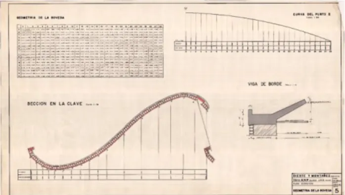
These construction drawings, specially the “Vault Geometry” sheets were then used for the parametrical modelling of the Seaport Deposit’s Gaussian Vaults roof surfaces by means of the plug-in Grasshopper ©, associated with Rhinoceros 3d © version 5.0. The coordinates of the construction drawings’ geometry sheet (Figure 7) were used to model the key cross-section of a structural module of the roof as well as the beginning and ending catenary (longitudinal) sections of the script. These “Vault Geometry” sheets have “vault geometry tables”, where the
The International Archives of the Photogrammetry, Remote Sensing and Spatial Information Sciences, Volume XLII-2/W9, 2019 8th Intl. Workshop 3D-ARCH “3D Virtual Reconstruction and Visualization of Complex Architectures”, 6–8 February 2019, Bergamo, Italy
coordinates of every control point on the surface is displayed. In these tables, cross-sections range from 0-28, and longitudinal sections range from A-R. For example, the point conformed by the intersection of the cross-section “2” and the longitudinal section “A” points out to a point that elevates itself 0,3 m from the lowest point of the cross-section. Still interpreting such tables, this particular cross-section has its points 159,8 cm from the key section.
Such sections, as well as the edge sections constitute the edges of the roof surface, which on the Grasshopper © script below (Figures 8 a-b) constitutes the “roof modelling base” step. These edges were then united using the “loft” component on the “roof surface” step of the model. The Grasshopper © model itself also had the “height” and “vertical guides to the cross section” groupings of components modeled in order to assure the accuracy of the modeled surface. before its rapid prototyping, the resulting surface had their resulting control points confronted with the “Vault geometry” sheets in order to verify its accordance to their original construction drawings.
Figure 7: Example of Eladio Dieste’s Seaport Deposit of Montevideo’s original construction drawing sheet obtained during the research. This specific sheet establishes the geometrical coordinates of the Roof Surface.
© Dieste & Montañez / Udelar Archives.
(a)
(b)
Figure 8: The Grasshopper © script used in this research to model the Seaport of Montevideo’s Gaussian Vault roof surface. In (a) the components used are shown in their operating sequence and grouped by color as according to their functions. In (b), these groupings have their main output highlighted in order to further explain the outputs of each portion of the algorithm.
The resulting model was equivalent to half of a structure roof module, constituted by two symmetrical halves on all of Dieste’s
Gaussian Vaults. The consolidated digital models were then prepared for rapid prototyping by being transferred from Grasshopper © into Rhinoceros 3d © by means of the command “bake”. Once in Rhinoceros ©, the model was scaled with a factor of ten for the initial rapid Prototyping, for the aimed scale was 1:100 in order to produce the largest model possible with only one printing session and thus potentializing the piece’s manipulation by hand.
The Grasshopper © model was produced in millimeters in order to avoid video card issues, for the model would lag and freeze upon working with meters on the available Alienware pc with a i7 processor of 2.60 GHz. Each piece was rotated in Rhinoceros © on their z-axis by means of the “Rotate3d” command in order to better fit the Felix 3.1 © output tray, and had their surface extruded in 2 cm with the command “ExtrudeSrf” in order to establish a width with which the filament would be able to hold a grip produce a surface without falling a part or skipping command sequences. Also, previous failed attempts to produce these pieces revealed that a 2 cm width, equivalent to 2 mm in a 1:100 scale, produced models which were less sensitive to the vibrations of the 3d printing process, and thus achieved a formal output without significant deformations.
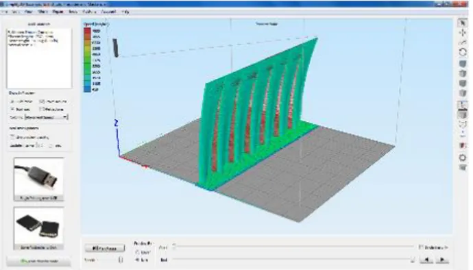
Such processed Rhinoceros © models were then translated to the Felix 3.1 © software Simplify 3d © in order to generate the .stf file to be sent to the 3d printer. The visualization on the Simplify 3d (Figure 9) was crucial to determine the appropriate position for the 3d printing of the pieces, showing to the research team that the pieces would not fit on the tray if they were to be laid vertically. This software also allowed for the simulation of the printing process and the extraction of the time span of the production, as well as the control of the quantity and density of support material, which helps to stabilize the 3d printing but could break the model upon its removal.
Figure 9: Verification of the fitting of the Rhinoceros © model on the Felix 3.1 © Simplify 3d © software. This verification allowed for the simulation of the 3d printing process and adjustments therein.
Each half-module had a printing time of approximately 4 hours and 33 minutes, and had an acrylic support laser-cut in order to have it stand on their mdf bases on their natural position (Figure 10). This acrylic support had their curvature and dimensions extracted from the construction drawings dimensions and was laser-cut using the GLC-1060 machines from Glorystar. All the laser-cutting machines and 3d printing machines used in this research are located at the FAU – Mackenzie rapid prototyping lab, in Sao Paulo, Brazil.
The International Archives of the Photogrammetry, Remote Sensing and Spatial Information Sciences, Volume XLII-2/W9, 2019 8th Intl. Workshop 3D-ARCH “3D Virtual Reconstruction and Visualization of Complex Architectures”, 6–8 February 2019, Bergamo, Italy
Figure 10: 3d printing process and half-a-module produced.
The whole roof surface was produced by using the same methodological procedure but was produced in four pieces of 1:200 each, in order to fit into the Felix 3.1 © tray. Other differences include the fact that the “baked” structural surface in Rhinoceros © was copied 7 times longitudinally in order to obtain half of the design’s existing length as according to the construction drawings. Each produced piece consisted of half-a-module of one half of the surface, that is, one quarter of the surface. In order to obtain a proper fit on the printing tray and avoid losing stability, the pieces were laid horizontally on Simplify 3d, and support material was added to the openings and to form a robust base on which the model would be attached during the printing process (Figure 11).
Figure 11: Adjustment of the whole surface components on Simplify 3d.
Figure 12: 3d printing process and assembling of the complete whole roof surface on a mdf base.
Due to the fact that the height of the model was considerably close to the upper printing limit of the tray, the amount of support on the openings and base was obtained through experimentation, for the two first attempts to print these whole roof pieces were deformed for the model ceded to its own self-weight and the filament deposit hit the wrong coordinates. The quarters of the whole roof surface had a production time of 6h30 each, with 30 minutes intervals between each printing in order to set up the next batch, totaling 28 hours of work (Figure 12). The final roof
surface was assembled on a mdf base that was 30 cm x 50 cm in order to accommodate the surface, whose model measured 23 cm x 40 cm. In order to have the surface stand, there were produced mdf supports with the same geometry as the roof surface right on the meeting point of the module halves (Figure 13).
Figure 13: intermediate supports were laser-cut in order to visualize the whole roof surface on a mdf base.
Such 3d printings were aimed to gather a full comprehension of the geometry of the Gaussian Surface’s structural modules separately as well as the total surface as a whole. Yet, these models did not show the fitting of Dieste’s structural unit, the brick, on the surfaces. Therefore, another Grasshopper © script (Figure 14) was conceived where the bricklaying process could be contemplated by mapping the position of the bricks on the surface by means of their amount and dimensions present on the construction drawings. The component that gathered the bricks’ information and allowed for their extraction within the total surface is called “IsoTrim”, and its outputs were confirmed by means of the components “Dimensions” and “IsPlanar”, in order to verify the brick’s longitudinal and transverse dimensions as well as to check if they were planar. After this verification, the resulting bricks were extruded with the component “Extrude” as according to the bricks’ registered height on the construction drawings. The resulting model (Figure 15) was readied for digital fabrication on the Felix 3.1 © using the same procedures as for the other models, but the opted scale was 1:30 in order to fully visualize the bricklaying on the surface. (Figure 16).
Figure 14: Grasshopper © script created to verify the bricklaying on the Gaussian Vault surface of the Seaport Deposit of Montevideo.
The digital model resulting from Grasshopper © script allowed for the digital fabrication of four pieces of the roof surface of the Seaport Deposit of Montevideo in a scale of 1:30. The resulting model was 18,93 cm x 74,56 cm and allowed for the verification of the bricks position on both the surface as a whole and in determined critical areas of the surface.
The International Archives of the Photogrammetry, Remote Sensing and Spatial Information Sciences, Volume XLII-2/W9, 2019 8th Intl. Workshop 3D-ARCH “3D Virtual Reconstruction and Visualization of Complex Architectures”, 6–8 February 2019, Bergamo, Italy
Figure 15: The digital model resulting from Grasshopper © script (left) allowed for the digital fabrication of four pieces of the roof surface of the Seaport Deposit of Montevideo in a scale of 1:30. This scale provides the possibility of verifying of the bricklaying in each of the four printed pieces (right).
Figure 16: The complete roof surface of the Gaussian Vaults of the Seaport Deposit of Montevideo in a scale of 1:30.
4. CONCLUSIONS
The outputs of this research were an understanding that, Eladio Dieste sought a conciliation between the ideal geometry for such surfaces, aiming for structural efficiency by asserting a minimal inertia momentum on roof’s cross sections, the brick as a construction unit, the indigenous workers expertise, and the material limitations of the building’s economic context. The analysis of the primary and secondary sources reveal that such construction procedures were in fact open to suggestions and inputs by the workers, which came in together with Dieste’s empirical design process approach. Such empirical approach could be associated with what Kenneth Frampton (2015) defines as the characteristically Latin-American modern architecture “will-to-build”.
The parametrical modelling and digital fabrication of the Gaussian Surface of the Seaport Deposit of Montevideo revealed that the uttermost edge of the cross-section of the roof, the roof edge, is not totally planar. The slight curvature on these edges suggest that the meeting of the geometries of the roof and lateral walls had to be complemented with mortar or edge beams in order to fill the resulting orifices and areas where there was no contact. The manner in which this complementation was made is not registered in the primary and secondary sources that were consulted and thus corroborate with the fact that Eladio Dieste actively included his construction workers on the definition of design and constructive solutions, relying on their long-age expertise and contact with masonry construction techniques.
The Parametric Modelling and the Digital Fabrication also revealed interesting inputs on the bricklaying process and the formwork itself. The existing construction drawings about Eladio Diester do not specify the exact dimensions of the formwork he used on his Gaussian Vaults, especially confronting the spatial nature of these elements as seen in the photographic registry of their construction process and the planar registry on the actual construction drawings. If the actual curvature of the surface was determined by the positioning of the transverse ribs on the coordinates determined by the “Geometry Sheets”, the Parametric Modelling and Digital Fabrication revealed that the bricks had to be actually be cut in the most extreme concave areas of curvature. Such brick cutting is not present in any of the bricklaying registry consulted. The cut bricks appear as intersecting on the parametric modelling on such extreme concave curvature areas, which are located on the tallest points of the Gaussian Vaults’ surfaces. On the Digital Fabrication itself, the intersecting of the Bricks on the Parametric Model is identified by the lack of spacing amongst the brick on the concave portions of the surface (Figure 17, to the left)
Figure 17: The interpretation of the bricklaying process using the Digitally Fabricated model allowed for exploration of the relationships of the construction process and resulting geometry.
On the other hand, the convex portions of the surface had to be adjusted on the Simplify 3d for there was too much spacing between the bricks and they were breaking apart. This can be seen on Figure 17, especially on the second component of the surface from left to right. The first image (to the left) of Figure 17 also demonstrates the larger spacing between the bricks on a previous Digital Fabrication attempt of the surface, which actually broke and was glued on this particular area.
If on the upper portion of the surface the ceramic blocs conduced the surface without difficulty, on the lower part it was not the case. The software Simplify 3D allowed for the expansion of the bricks on this portion of the surface in order to allow contact between the blocks. To maintain the geometry on the lower part of the convex parts, Eladio Dieste must have sought to proceed as done with the irregular roof edges, mortar fillings.
Figure 18: The Parametric Modeling allowed for the identification of the precise geometry of the interstice between the modules of the Gaussian Roofs, where the openings are located.
The International Archives of the Photogrammetry, Remote Sensing and Spatial Information Sciences, Volume XLII-2/W9, 2019 8th Intl. Workshop 3D-ARCH “3D Virtual Reconstruction and Visualization of Complex Architectures”, 6–8 February 2019, Bergamo, Italy
Also, the exact geometry of the roof openings was an incognito on the existing registries. The parametric modelling allowed for the identification of the geometry of the interstice between the edges of the adjacent structural modules, that is, the upper catenary edge of the finishing module and the lower catenary edge of the beginning module (Figure 18). The resulting surfaces are laid on the YZ plane and are bounded by two catenary curves. The lack of precise constructive specifications alongside Dieste’s strong presence on the work-site and his strong reliability on his construction workers could be interpreted in a way as that the exact ending of the openings could have been determined during the construction process itself.
ACKNOWLEDGEMENTS
This study was financed in part by the Coordenação de Aperfeiçoamento de Pessoal de Nível Superior - Brasil (CAPES) - Finance Code 001.
This study was only possible due to the construction drawings provided by the Dieste & Montañez / UdelaR Archives.
REFERENCES
Anderson, S. (ed.) 2004. Eladio Dieste: Innovation in Structural
Art. New York: Princeton Press.
Avery Index to Architectural Periodicals, Pro Quest, accessed 1 set. 2018, < https://www.proquest.com/products-services/avery-set-c.html>.
Baldellou, M. A. And Capitell, A. 2001. Summa Artis XL: Arquitectura española del siglo XX. Madrid: Espasa-Calpe. Banham, R. 1984. The architecture of the well-tempered
environment. 2nd ed. Chicago: University of Chicago Press.
Bechthold, M. 2008. Innovative Surface Structures: Technologies and Applications. New York: Taylor & Francis.
Bonta, J. 1963. Eladio Dieste. Buenos Aires.
Carbonell, G. 1987. Eladio Dieste – La Estructura Ceramica. Bogotá: Ed. Escala.
Carvalho, M C R 2006, ‘Caracterização da Tecnologia Construtiva de Eladio Dieste: Contribuições para a Inovação do Projeto Arquitetônico e da Construção em Alvenaria Estrutural’, PHD thesis, Santa Catarina Federal University, Florianópolis. Dieste E. 1978. Pandeo de láminas de doble curvatura. Montevideo: Ediciones de la banda oriental.
Felix Printers. 2017. Felix 3.1. Felix Printers. (2017). Simplify 3d.
Florio, W. 2011. ‘Modelagem paramétrica na concepção de elementos construtivos de edifícios complexos’, Proc. XV
Encontro Nacional de Tecnologia no Ambiente Construído, 6(2),
p2943-2953.
Frampton, K. 2015. História crítica da arquitetura moderna. São Paulo: Martins Fontes.
Gross, M. and Goldschmidt, G. 2008. ‘A Perspective on Computer Aided Design after Four Decades’, Proc. 26th
international conference on Education in Computer-Aided Architectural Design in Europe (eCAADe), 26(4) p169-178.
Maluenda, A. E. 2016. La arquitectura moderna em
Latinoamérica. Madrid: Reverte.
Monedero, J. 2000. ‘Parametric design: a review and some experiences’, Automation in Construction (AIC), 9(4), p369-377. Ochsendorf, J. A. 2004. ‘Eladio Dieste as Structural Artist’ in Anderson, S. (ed.). Eladio Dieste: Innovation in Structural Art. New York, Princeton Architectural Press, 2004. p94-105. Pedreschi, R. 2000. The Engineer’s Contribution to
Contemporary Architecture. London: Thomas Telford Ltd.
Pedreschi, R. and Theodossopoulos, D. 2006. ‘The Double-Curvature Masonry Vaults of Eladio Dieste’, Proc. Institution of
Civil Engineers, 60(SBI), p3-11.
Pottmann, H., Asperl A., Hofer, M. and Kilian, A. 2013.
Architectural Geometry. Exton: Bently Institute Press.
Robert McNell & Associates. 2017. Grasshopper. Robert McNell & Associates. 2017. Rhinoceros.
Sass, L. and Oxman, R. 2006. ‘Materializing design: the implications of rapid prototyping in digital design’, Design
Studies, 27(3), p325-355.
Schodek, D. and Bechthold, M. 2014. Structures. 7th ed. Pearson Education Limited.
Seely, J. C. K. 2000. ‘Digital Fabrication in the Architectural Design Process’, Master’s thesis, Massachusetts Institute of Technology, Cambridge, MA, USA.
Torrecillas, A. (ed.) 1996. Eladio Dieste 1943-1996. Sevilla: Fundación Barrié.
Web of Science, Clarivate Analytics, accessed 1 set. 2018, < https://clarivate.com/products/web-of-science/>.
Woodbury, R. 2010. Elements of Parametric Design. London: Routlege.
The International Archives of the Photogrammetry, Remote Sensing and Spatial Information Sciences, Volume XLII-2/W9, 2019 8th Intl. Workshop 3D-ARCH “3D Virtual Reconstruction and Visualization of Complex Architectures”, 6–8 February 2019, Bergamo, Italy