UNIVERSITY
OF TRENTO
DIPARTIMENTO DI INGEGNERIA E SCIENZA DELL’INFORMAZIONE
38050 Povo – Trento (Italy), Via Sommarive 14 http://www.disi.unitn.it
A TWO-STEP INVERSE SCATTERING PROCEDURE FOR THE QUALITATIVE IMAGING OF HOMOGENEOUS CRACKS IN KNOWN HOST MEDIA – PRELIMINARY RESULTS
A. Massa, and ElediaLab
November 2008
COMMERCIAL IN CONFIDENCE
ELEDIALab: DIT-PRJ-07-062 - Rapporto Tecnico N.9 page 1/8
ELEctromagnetic DIAgnostics Lab.
Information Engineering and
Computer Science Dept.
University of Trento
Via Sommarive 14, 38050 Trento, ITALY
Phone +39 0461 882057 Fax +39 0461 882093
E-mail:
[email protected]
Contract No. DIT-PRJ-07-062
Rapporto Tecnico N. 9
“A Two-Step Inverse Scattering Procedure for the
Qualitative Imaging of Homogeneous Cracks in
Known Host Media – Preliminary Results”
Document 1 - Version: 1.0 Document status: Draft
Access: Confidential Date: 08/09/2008
ELEDIALab: DIT-PRJ-07-062 - Rapporto Tecnico N .9 page 2/8 Index Index... 2 1 ABSTRACT... 3 2 INTRODUCTION... 3 3 MATHEMATICAL FORMULATION ... 3 4 NUMERICAL ANALYSIS ... 7 5 CONCLUSIONS ... 8 6 REFERENCES... 8
COMMERCIAL IN CONFIDENCE
ELEDIALab: DIT-PRJ-07-062 - Rapporto Tecnico N .9 page 3/8
1 ABSTRACT
In the framework of nondestructive evaluation and testing, microwave inverse scattering approaches demonstrated their effectiveness and the feasibility of detecting unknown anomalies in dielectric materials. In this paper, an innovative technique is proposed in order to enhance their reconstruction accuracy. The approach is aimed at firstly estimating the region-of-interest where the defect is supposed to be located and then at improving the qualitative imaging of the crack through a level-set based shaping procedure. In order to assess the effectiveness of the proposed approach, representative numerical results concerned with different scenarios and blurred data are presented and discussed.
2 INTRODUCTION
Nondestructive testing and evaluation (NDE/NDT) techniques are aimed at detecting unknown defects and other anomalies buried in known host objects by means of non-invasive methodologies [1]-[3]. In such a framework, electromagnetic inverse scattering approaches can play an important role. As an example, some approaches that approximate defective regions with rectangular shapes have been proposed [4][5]. Despite the satisfactory results, such techniques are adequate when facing NDE/NDT problems where the retrieval of the positions and the rough estimation of the sizes of the defects are enough, but they cannot be reliably used when an accurate knowledge of the shapes of the defects is needed as in some industrial processes and usually in biomedical diagnosis. Notwithstanding, they are useful for providing a “first-step” information concerned with a rough localization of the defects to be further improved by means of a successive refinement reconstruction carried out with suitable contour detection methods.
Towards this end, this paper presents a two-step procedure aimed at improving the reconstruction of [4][5]. More in detail, starting from the knowledge of the scattered field with and without the defect, the approximate problem in which the defect is assumed of simple shape (e.g., a rectangle) is reformulated in terms of an inverse scattering one and successively solved by means of the minimization of a suitably-defined cost function [6]. After such a step, the region-of-interest (RoI) where the defect is supposed to be located is determined and the second retrieval phase takes place by applying a shape-based optimization technique based on the numerical evolution of a level set function [7].
3 MATHEMATICAL
FORMULATION
Let us consider a two-dimensional scenario where a homogeneous defect (or crack) characterized of unknown position rc =(xc,yc) and shape Ω lies in a cylindrical host region characterized by known relative permittivity and conductivity . The defective host medium is probed by V electromagnetic TM plane waves with an incident field
D D ε σD
( )
r E( )
r z E incv vinc = ˆ and the induced electromagnetic field, Evtot
( )
r , is given by( )
r E( )
r( )
r'E ()( ) ( )
r'G0 r/'rdr' E D v c tot v inc v tot = +∫∫
τ (1)where G is the free-space Green’s function and
( ) ( )
( )0 2 1 σπε ε τ fr j r r = − −
0 is the object function ( being
the working frequency), or analogously in a more “practical” expression [8]
ELEDIALab: DIT-PRJ-07-062 - Rapporto Tecnico N .9 page 4/8
( )
r =E ( )( )
r +∫ ∫
Ω Ω( )
r'E ()( ) (
r'G1 r'/r)
dr' E totv c v cf inc v tot τ (2)(
r r)
G1 '/by considering the inhomogeneous Green’s function and the total electric field in the scenario without defects Eincv (cf)
( )
r defined as follows( )
( )
( )( ) (
' 0 '/)
' ) ( r E r E r G r rdr E D v cf inc D v inc v cf inc = +∫ ∫
τ . (3)where τΩ
( )
r is the differential object given by( ) ( ) ( ) ⎩ ⎨ ⎧ Ω ∉ Ω ∈ − − = − Ω r if r if j r C D f D C 0 0 2πε σ σ ε ε τ . (4)
With reference to the “differential formulation”, the first step of approach considers the partitioning of in and the only-one computation of the inhomogeneous Green’s matrix [ of × entries according to the procedure detailed in [8]. Then, the RoI
D N1 G1] N1 N1
R is modeled with a rectangular
homogeneous shape described through the coordinates of the center rR =(xR,yR), its length , its
side , and the relative orientation . Accordingly,
R
L
R
R
W θR turns out to be fully described by means
the following object function profile
( )
( )
[
]
[
]
⎩ ⎨ ⎧ ∈ − ∈ − = Ω otherwise Y and X if r r R R R R L W W L R 0 , , 2 2 2 2 τ τ (6)where X =(x−xR)cosθR+(y−yR)sinθR and X =(x−xR)sinθR+(y−yR)cosθR. Under these assumptions, the
unknown array
( )
{
}
[
=]
∈Ω = P P v c tot R R R R R y L W E r p P r x , , , ,θ , () ; 1,..., , χ (7)is determined by solving the inverse scattering problem formulated in terms of an optimization one. More in detail, starting from the knowledge of the data samples collected in the observation domain
[i.e., the total field with the defect ( )m and without the defect
v tot r E ( )m v cf tot r E ( ) O , ] and in the
investigation domain [i.e.,
M m=1 K, , χ D ( ) n v inc r
E , n=1,K,N1], is obtained by minimizing the mismatching
between estimated and measured scattering data evaluated through the computation of Θ1( )χ
( ) ( ) ( ) ( ) ( ) ( ) ( ) ( )
[
]
( ) ( ) ( ) ( ) ( ) ( ) ⎪ ⎪ ⎪ ⎭ ⎪⎪ ⎪ ⎬ ⎫ ⎪ ⎪ ⎪ ⎩ ⎪⎪ ⎪ ⎨ ⎧ ⎥ ⎦ ⎤ ⎢ ⎣ ⎡ − + + + ⎪ ⎪ ⎪ ⎭ ⎪⎪ ⎪ ⎬ ⎫ ⎪ ⎪ ⎪ ⎩ ⎪⎪ ⎪ ⎨ ⎧ − ⎥ ⎦ ⎤ ⎢ ⎣ ⎡ − − = Θ ∑∑ ∑∑ ∑ ∑∑ ∑∑ ∑ = = = = = = = = = = 2 1 1 2 1 1 1 , 1 ) ( ) ( 2 1 1 2 1 1 1 , 1 ) ( ) ( 1 1 1 / / V v N n n v inc V v N n P p p n R p v c tot p R n v tot n v cf tot V v M m m v inc m v tot V v M m P p p m R p v c tot p R m v cf tot m v tot r E r r G r E r r E r E r E r E r r G r E r r E r E τ τ χ (8)COMMERCIAL IN CONFIDENCE
ELEDIALab: DIT-PRJ-07-062 - Rapporto Tecnico N .9 page 5/8
{
j q Q}
q j ,..., 1 , = = χ χAs far as the minimization process is concerned, Q trial solutions are randomly
initialized ( , j being the iteration index) and an iterative procedure takes place until a stopping criterion holds true (
0 = j
( )
[
]
{
}
( )
1 1 χopt <γth Θ or , max J j= j q J j Q q opt χχ =argmin=1,K, min=1,K,maxΘ1 ). At each iteration, the
following operations are performed:
a) the iteration index is updated (j= j+1);
b) a set of genetic operators described in [5] is applied to χ j−1 in order to generate the j-th [χj =ℑ
( )
χj−1 ];( )
[
]
{
i}
opt j i j opt χ χ =argmin= K1, , Θ1{
q Q[
( )
qi]
}
i opt χ χ =argmin = K1, , Θ1c) the best trial solution achieved so far, being , is
stored and its fitness evaluated
( )
j optχ
1
Θ in order to check the threshold condition for the stopping
criterion.
At the end of the first step, the GA-based optimization returns the array χopt that defines the RoI R
( )
{
}
[
xR yR LRWR R Etotv c rP p P]
opt= ˆ ,ˆ ,ˆ , ˆ ,θˆ, ˆ () ; =1,...,
χ (9)
where the superscript ^ denotes the estimated values.
r r
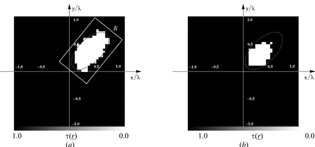
1.0 τ() 0.0 1.0 τ() 0.0 (a) (b)
Fig. 1. Experiment A – (a) Reconstruction after the first step (i.e., the RoI R) and dielectric distribution estimated at the end of the two-step procedure; (b) Dielectric distribution estimated by means of the “bare”
level set approach (i.e., R ≡ D).
The second step of the approach is aimed at refining the estimate of the defect starting from the knowledge coming from the first step (i.e., the homogeneous defect lies in R). Towards this purpose, a level-set-based strategy is employed. The algorithm is initialized by defining an elliptic trial shape Ψ0 centered at , with axes equal to rˆR LˆR 2 and WˆR 2, respectively, and rotated by .
Then, the Level Set
R
θˆ
is defined in Ω
0
φ according to the rule based on the oriented distance function [9]. In particular, φ0
( )
rn is equal to minr∂Ψ0 r∂Ψ0 −rn if rn∈Ψ0, and −minr∂Ψ0 r∂Ψ0 −rn otherwise,being a point belonging to the contour of Ψ0
0
Ψ ∂
r [7][9]. Concerning the numerical implementation,
is discretized in cells and the following sequence is iteratively applied:
ELEDIALab: DIT-PRJ-07-062 - Rapporto Tecnico N .9 page 6/8 Fig. 2. Experiment A – Area error versus SNR.
r r
1.0 τ( ) 0.0 1.0 τ() 0.0 (a) (b)
Fig. 3. Experiment B - (a) Reconstruction after the first step (i.e., the RoI R) and dielectric distribution estimated at the end of the two-step procedure; (b) Dielectric distribution estimated by means of the “bare” level set
approach (i.e., R ≡ D).
a) the accuracy of the current trial shape Ψk in retrieving the actual shape of the defect is evaluated by computing the value of the following metric
( )
( ) ( )( )
( ) (
)
( ) ( )[
]
⎪ ⎪ ⎪ ⎭ ⎪⎪ ⎪ ⎬ ⎫ ⎪ ⎪ ⎪ ⎩ ⎪⎪ ⎪ ⎨ ⎧ − ⎥ ⎦ ⎤ ⎢ ⎣ ⎡ − − = Θ ∑∑ ∑∑ ∑ = = = = = Γ Γ 2 1 1 2 1 1 1 , 1 ) ( ) ( 2 2 / V v M m m v inc m v tot V v M m N p p m R p v c tot p k m v cf tot m v tot k r E r E r r G r E r r E r E τ τ (10) where k( )
p r Γτ is the differential object function equal to
(
)
( )0 2πε σ σ ε εC D f D C j − − − if φk
( )
rp ≤0 and otherwise. Furthermore, 0 ( )m v cf tot rE ( ) is the solution of the following equation:
( )
( )
∑
( ) (
)
= + = 1 1 0 ) ( ) ( / N n n m n v cf tot D m v inc m v cf tot r E r E r G r r E τ (11) ) or b) the level set based process ends if a fixed number of iteration is performed (k<Kmaxand is assumed as the crack profile. Otherwise, the level set function ( )τk <γth
Θ2
opt k
Ψ φk is
COMMERCIAL IN CONFIDENCE
ELEDIALab: DIT-PRJ-07-062 - Rapporto Tecnico N .9 page 7/8
( ) ( )
{ ( )}{
( )
}
q k n k q k q k r H r t r r φ ν φ φ −ℵ = Δ − +1 (12)( )
{
k rq}
Hφwhere stands for the numerical counterpart of the Hamiltonian operator [9][10] and Δt is
the time-step parameter chosen according to the Courant-Friedrich-Leroy condition [11]. Moreover, ( )n
k r
ν is the velocity function determined by solving the adjoint problem as detailed in [7][9].
4 NUMERICAL
ANALYSIS
This section is devoted to a numerical analysis of the proposed approach. A set of selected and representative numerical results related to a couple of experiments are reported and discussed for pointing out the improvement in the crack detection and shaping.
The first experiment (indicated as “Experiment A”) considers an unknown void defect of elliptical cross-section that lies in a square lossless host medium of side and characterized by a dielectric permittivity equal to . The defect is located at
λ 0 . 2 = D L (11/30λ,11/30λ) = c r and rotated by 0 . 2 = D ε
with axes equal to 4
/
π 2/5λ and 11/50λ, respectively. The scenario has been probed by V =30 orthogonal and equally-spaced angular directions and the field has been measured at M =30 points. Moreover, the scattering data have been blurred with an additive noise of Gaussian-type characterized by a fixed signal-to-noise ratio (SNR).
Concerning the numerical procedure, has been discretized in and in sub-domains.
D 289 Ω
1=
N N2=441
Fig. 4. Experiment B – Area error versus SNR.
As an example, Figure 1(a) shows the reconstruction result from the two-step procedure in correspondence with . As it can be observed, the support of the defect (whose actual perimeter is evidenced by the dotted line) belongs to the RoI R (dash-dotted line) estimated at the end of the first step. However, the crack dimension is largely overestimated. On the contrary, the shape of the crack is more faithfully retrieved, although the non favorable signal-to-noise ratio. Such an event is quantitatively quantified by the value of the localization error
dB SNR=10 % 2 . 1 2 = δ [12], that improves by 30% with respect to the single-step inversion. For comparison purposes, Figure. 1(b) shows the reconstruction obtained by the “bare” level set method setting R ≡ D and discretizing the domain such that the spatial resolution is equal to that Fig. 1(a). As it can be noticed, the reconstruction worsen.
ELEDIALab: DIT-PRJ-07-062 - Rapporto Tecnico N .9 page 8/8
As far as the area error Δ [12] is concerned, Figure 2 shows the behaviour of the error figure versus the SNR. As it can be noticed, the two-step approach turns out to be more robust to the blurring on data and the resulting performances are better of an amount between 150% and 100%.
The “Experiment B” deals with a more complex cross-section shape of defect indicated by the dotted line in Fig. 3(a). As an example, let analyze the case of when the profile reconstructed by the proposed method is shown in Fig. 3(a), while Figure 3(b) gives the dielectric distribution estimated by the “bare” level set. Starting from the estimation of the region-of-interest, the two-step approach provides a satisfactory reconstruction improving both the localization error and the area error with respect to the first step (
dB SNR=20 , ; % 5 . 1 1 = δ δ2 =0.5% Δ1=3.7%, ). Similar
considerations hold true when smaller SNRs are considered, as pointed out by the values of the area error pictorially reported in Fig. 4.
% 5 . 1 2 = Δ
5 CONCLUSIONS
In this letter, an innovative two-steps procedure for NDE/NDT applications has been proposed and preliminary assessed. The method consists of a first step aimed at determining the region of interest where the defect is supposed to be located and a successive shaping process for enhancing the qualitative imaging. The approach has been evaluated by considering blurred synthetic data and different crack cross-sections. The achieved results have pointed out the effectiveness of the approach, thus suggesting its future employment in biomedical imaging.
6 REFERENCES
[1] P. J. Shull, Nondestructive Evaluation: Theory, Techniques and Applications. CRC Press, 2002.
[2] R. Zoughi, Microwave Nondestructive Testing and Evaluation, Kluwer Academic Publishers, The
Netherlands, 2000.
[3] J. C. Bolomey, “Recent European developments in active microwave imaging for industrial, scientific and medical applications,” IEEE Trans. Microwave Theory Tech., vol. 37, pp. 2109–2117, June 1989.
[4] K. Meyer, K. J. Langenberg, and R. Schneider, “Microwave imaging of defects in solids,” in Proc. 21st Annual Review of Progress in Quantitative NDE, Snowmass Village, CO, July 31-Aug. 5 1994.
[5] S. Caorsi, A. Massa, M. Pastorino, and M. Donelli, “Improved microwave imaging procedure for nondestructive evaluations of two-dimensional structures,” IEEE Trans. Antennas Propagat., Vol. 52, pp. 1386-1397, Jun. 2004.
[6] Y. Rahmat Samii and E. Michielssen, Electromagnetic Optimization by Genetic Algorithms. New York: Wiley 1999.
[7] O. Dorn and D. Lesselier, “Level set methods for inverse scattering”, Inverse Problems, 22, pp. R67-R131, 2006.
[8] S. Caorsi, G. L. Gragnani, M. Pastorino, and M. Rebagliati, “A model-driven approach to microwave diagnostics in biomedical applications,” IEEE Trans. Microwave Theory Tech., vol. 44, pp. 1910-1920, 1996. [9] A. Litman, D. Lesselier, and F. Santosa, “Reconstruction of a two-dimensional binary obstacle by controlled
evolution of a level-set,” Inverse Problem, Vol. 14, pp. 685-706, 1998.
[10] S. Osher and J. A. Sethian “Fronts propagating with curvature-dependent speed: algorithms based on Hamilton–Jacobi formulations,” J. Comput. Phys. 79, pp. 12–49, 1988.
[11] J. A. Sethian, Levelset Methods and Fast Marching Methods. Monographs on Applied and Computational Mathematics, Cambridge: Cambridge University Press, 2nd ed., 1999.
[12] S. Caorsi, M. Donelli, and A. Massa, “Detection, location, and imaging of multiple scatterers by means of the iterative multi-scaling method,” IEEE Trans. Microwave Theory Tech., vol. 52, no. 4, pp. 1217-1228, 2004.