Department of Civil and Environmental Engineering
Doctoral School in Structural, Earthquake and Geotechnical Engineering
XXV cycle
B
EHAVIOUR OF
C
OUPLING
B
EAMS
R
ETROFITTED WITH
A
DVANCED
C
EMENTITIOUS
C
OMPOSITES:
E
XPERIMENTS AND
M
ODELLING
Doctoral Dissertation of:
Milot M
UHAXHERISupervisors:
Prof. Marco di P
RISCOProf. Liberato F
ERRARAThe Chair of the Doctoral Program:
Prof. Roberto P
AOLUCCIMilot Muhaxheri 754203
Behaviour of Coupling Beams Retrofitted with Advanced Cementitious Composites:
Experiments and Modelling
© March 2014
e-mail:
B
EHAVIOUR OF
C
OUPLING
B
EAMS
R
ETROFITTED WITH
A
DVANCED
C
EMENTITIOUS
C
OMPOSITES:
E
XPERIMENTS AND
M
ODELLING
A Thesis
Presented to
The Academic Faculty
by
Milot M
UHAXHERIIn Partial Fulfilment
Of the Requirements for the degree
Doctor of Philosophy
in
Structural, Earthquake and Geotechnical Engineering
Doctoral School in Structural, Earthquake and Geotechnical Engineering Department of Civil and Environmental Engineering
Politecnico di Milano XXV Cycle
BOARD COMMITTEE:
Prof. Raffele Ardito Prof. Fabio Biondini Prof. Gabriella Bolzon Prof. Claudia Comi Prof. Alberto Corigliano Prof. Dario Coronelli Prof. Marco di Prisco Prof. Claudio di Prisco Prof. Liberato Ferrara Prof. Attilio Frangi Prof. Elsa Garavaglia Prof. Cristina Jommi Prof. Pier Giorgio Malerba Prof. Anna Pandolfi Prof. Roberto Paolucci Prof. Umberto Perego Prof. Federico Perotti Prof. Lorenza Petrini Prof. Gianpaolo Rosati Prof. Luigi Zanzi
Fibre reinforced cement based composites due to their enhanced mechanical performance, mainly for their peculiar tensile behaviour, in recent decades have attracted a great attention among research and engineers community as a replacement of conventional concrete or as strengthening/retrofitting solution in existing r/c structures. Usually the lateral resistance of medium and high rise buildings relies on r/c concrete core, which due to architectural restraints such as door or window opening results in structural division of core walls into singular shafts which usually are connected with deep beams by so called coupling beams. In order to provide a good transfer of forces between the shafts these beams should be properly designed, which requires a dense and complicated reinforcement arrangement. In this thesis the use of fibre reinforced cement based composites is explored as upgrading/retrofitting solution for the poorly designed coupling beams, namely the High Performance Cementitious Composite (HPFRCC) and Textile Reinforced Cementitious Composite (TRCC). This has involved a “multi-scale” studies which started from material characterization and moved up to structural element and to the structural level.
In order to design the experimental test specimens reference has been made to the case of a shear wall containing a typical door opening 900 mm wide (equal to the length of the coupling beam) and 2.1 m high; this resulted (assuming the inter-storey height equal to 2.7 m) in a depth of coupling beam equal to 600 mm and hence in a span to depth ratio of 1.5. The coupling beam was perceived to be a “poorly designed” element; just satisfying the minimum reinforcement requirement prescribed by design codes for non-seismic design situations. Previously calibrated numerical approach based on multi-fibre Timoshenko beam element was used for estimation of load bearing capacity of coupling beams with different strengthening typologies. The experimental campaign performed involved tests on “non-retrofitted” coupling beam specimens, through which it was possible to study the influence of the different resisting contributions (concrete tensile strength, longitudinal and transverse reinforcement), as well tests on retrofitted ones. Two retrofitting choices were pursued: with HPFRCC (6 specimens) and TRCC (2 specimens), tested both under monotonic and reversed cyclic displacements. In total 14 specimens were tested.
In order to have an insight into the results of the experimental results at member level a through characterization of the retrofitting material had also to be performed. A newly conceived test method known as Double Edge Wedge Splitting for the identification of material tensile behaviour of HPFRCC has been employed. Moreover the fracture toughness parameters were related to fibre density and orientation assessed both through non-destructive and non-destructive testing technique. Depending on the fibre orientation either a strain hardening or softening behaviour can be obtained. Constitutive laws were proposed in tension for both cases and have been implemented in “crush-crack” damage model.
The same numerical model used for modelling DEWS specimens, has been then applied to model the behaviour of HPFRCC coupling beams under monotonic loading, making reference to the experimental campaign performed at University of Michigan on 4 individual coupling beams, cast with either conventional reinforced concrete or HPFRCCs and with different reinforcement arrangements.
As a further step, an alternative modelling technique was explored using a multi-fibre Timoshenko beam element, which incorporates reliable description of unilateral effects of concrete cyclic behaviour, in which suitable assumptions resulting from the previous modelling phase were also incorporated. This approach has been then adopted to predict the cyclic behaviour of coupling beams made of or retrofitted with HPFRCCs and provided reliable description.
Finally, the results performed were employed to numerically asses the efficacy of coupling beams retrofitting on the structural performance of a shear wall. The efficiency of the HPFRCC retrofitting of a poorly designed coupling beam in recovering the same coupling action as a correctly designed one has been highlighted. The possibility of retrofitting coupling beam at selected locations along the wall height with equal structural performance was also addressed through a numerical parametric study.
expérimentateur trouve un résultat nouveau tout le monde y croit, sauf lui! »
J. Lemaitre and J. L.Chaboche
ACNOWLEGEMENTS
This research was jointly supervised by Prof. Marco di Prisco and Prof. Liberato Ferrara, to whom I am grateful for making this research possible through their efforts of finding the financial support to carry out the experiments and partially a year of my PhD studies. The fund was obtained from The Italian Department of Emergency Management in the framework of the ReLUIS project: “Development of new materials for seismic retrofitting”, which is gratefully acknowledged.
I am deeply indebted to both of them: to Prof. di Prisco for offering crucial suggestions to better develop this research and to Prof. Ferrara, not only for his advising excellence to tackle the rising problems throughout this research, but also for following and keeping me motivated and optimistic during all the PhD studies.
I owe a great debt of gratitude to the fundamental help and patience of Marco Lamperti who guided and taught me throughout these years to perform all the experiments, at Department of Structural Engineering of Politecnico di Milano. Indeed, I would like to thank also Tonino, Paolo, Giovanni, Andrea, Marco and Massimo the technicians of the Laboratory for Materials and Structures testing of Politecnico di Milano.
I also thank the students who accompanied me during experiments as a part of their degree fulfilment, Stefano Bufalino (BSc) at material level and Alessandro Spini (MSc) at structural level.
I would thank my colleagues at department, who provided a pleasant working and friendly environment.
Finally, I am beholden also to my family not only for their relentless love support, but also that could provide me the rest of financial maintenance to carry out the PhD studies.
1.1 Thesis outline ... 1
2 Literature Review ... 5
2.1 Coupling beams ... 5
2.1.1 Steel/composite coupling beams ... 8
2.1.2 HPFRCC coupling beams... 8
2.2 Design and modelling of the coupling beams ... 12
2.3 Retrofitting/strengthening of structural elements ... 14
2.4 HPFRCC as strengthening material ... 15
2.4.1 Flexural strengthening ... 15
2.4.2 Shear strengthening ... 17
2.5 Textile reinforced cementitious composites TRCC as retrofitting/strengthening material ... 18
2.5.1 Shear strengthening ... 18
2.6 Coupling beam strengthening techniques ... 20
2.7 Effect of coupling beam upgrade on structural behaviour ... 22
2.8 Fibre reinforced cementitious composites (FRCC) ... 23
2.8.1 Compression ... 26
2.8.2 Cyclic tension/compression ... 27
3 Material level investigation: Experimental identification and modelling selected retrofitting material ... 29
3.1 Characterization of fibre reinforced cementitious composites: Non-destructive and destructive testing ... 29
3.1.1 Sample preparation ... 29
3.1.2 Non-destructive method: physical background ... 31
3.1.3 Non-destructive measurement for fibre reinforced cementitious composites application ... 33
3.1.4 Correlation of non-destructive and destructive measurements to tensile fracture toughness ... 38
3.2 Continuum damage modelling ... 44
3.2.1 Scalar damage model – [Mazars, 1984] ... 44
3.2.2 “Crush-crack” damage model ... 47
3.3 Constitutive laws ... 49
3.3.1 Uniaxial Compression Constitutive law ... 49
3.3.2 Uniaxial Tension ... 50
3.3.3 Strain softening constitutive law – Consideration on conventional concrete 50 3.3.4 Strain softening constitutive law – Consideration on FRCC ... 51
3.3.5 Numerical modelling ... 55
4 Investigation at member level: Numerical modelling of the behaviour of
coupling beams ... 69
4.1 “Crush-crack” damage modelling ... 69
4.2 Timoshenko-beam fibre modelling ... 75
5 Investigation at structural member level: Design and planning of the experimental campaign ... 81
5.1 Specimen design: reinforcement cages ... 81
5.2 Strengthened coupling beams ... 83
5.3 Pre-design considerations ... 86
5.4 Elastic design of the setup ... 87
5.5 Final frame design ... 89
5.6 Test setup description ... 91
5.7 Testing programme ... 93 5.8 Production of specimens ... 94 5.9 Surface treatment ... 95 5.10 Materials ... 96 5.10.1 Concrete C 20/25 ... 96 5.10.2 Steel reinforcement ... 97
5.11 Casting procedure of the retrofitting/strengthening layer ... 97
5.11.1 HPFRCC ... 97
5.11.2 Textile reinforced cementitious composite ... 98
6 Investigation at structural member level: Experimental results ... 101
6.1 Coupling beams non-strengthened/retrofitted ... 101
6.1.1 Coupling beam without any steel reinforcement ... 101
6.1.2 Coupling beams with only longitudinal reinforcement ... 103
6.1.3 Coupling beam with longitudinal and transverse reinforcement ... 106
6.2 Retrofitted/strengthened coupling beams ... 114
6.2.1 Retrofitted/strengthened coupling beams with HPFRCC ... 114
6.2.2 Retrofitted pre-damaged coupling beams ... 120
6.3 Comparisons ... 130
6.4 Energy dissipation ... 133
6.4.1 Energy dissipation of coupling beams tested under monotonic loading ... 133
6.4.2 Energy dissipation of coupling beams tested under cyclic displacements .... 134
6.4.3 Axial Elongation... 139
6.5 Modelling ... 142
7 Structural level ... 145
7.1 Geometry ... 145
7.2 Reinforcement of the wall ... 148
7.3 Strengthening configuration of the wall ... 149
7.4 Coupling beam reinforcement ... 149
7.5 Strengthening of the coupling beams ... 150
7.5.1 Material definition ... 151
7.6 3 storeys shear wall ... 152
7.7.1 Non strengthened coupled shear wall (5 storeys) ... 154
7.7.2 Coupled shear wall strengthened with HPFRCC (5 storeys) ... 154
7.7.3 Coupled shear wall strengthened with r/c jacketing (5 storeys) ... 155
7.7.4 Strengthening efficiency on coupled shear walls ... 156
7.7.5 Efficiency parameter ... 156
7.7.6 Results of 5 storeys coupled shear wall ... 157
8 Conclusions and future research needs ... 161
Appendix ... 165
L
IST OF
F
IGURES
Figure 2.5 – Wall behaviour (a) under lateral load and (b) soil settlements ... 5
Figure 2.6 – Resisting mechanism of (a) coupled and (b) uncoupled wall systems ... 6
Figure 2.7 – Failure of coupling beams due to earthquake Alaska (Alaska Digital Archive)... 6
Figure 2.8 – Various reinforcing configurations for coupling beams ... 7
Figure 2.9 – Specimen geometries and reinforcement details (unit mm): (a) (CB1) and (CB2) specimens; and (b) (CB3) specimen [Yun et al., 2008] ... 9
Figure 2.10 – Test setup [Yun et al., 2008] ... 9
Figure 2.11 – Cyclic behaviour of specimen: (a) (CB1); (b) (CB2); and (c) (CB3) [Yun et al., 2008] ... 9
Figure 2.12 – Test setup employed [Canbolat et al., 2005] ... 10
Figure 2.13 – Uniaxial tensile response of specimen with polyethylene ... 11
Figure 2.14 – Geometries and the different reinforcement details [Canbolat et al., 2005] ... 11
Figure 2.15 – Cyclic behaviour of various specimens [Canbolat et al., 2005] ... 11
Figure 2.16 – (a) Specimen (MCB1) and (b) test setup ... 13
Figure 2.17 – Comparison between experimental investigation and numerical results: (a) (MCB1); (b) (MCB2); (c) (MCB3) and (d) (MCB4) ... 14
Figure 2.18 – Effects of axial restraining on specimen (MCB1) numerically assessed ... 14
Figure 2.19 – Categories of Textile reinforced composites (a) failure of fibres and (b) failure of matrix [Wiberg, 2003] ... 15
Figure 2.20 – (a) Geometry and loading of the specimen and (b) jacketing with HPFRCC [Martinola et al., 2010] ... 16
Figure 2.21 – Behaviour of the tested beams [Martinola et al., 2010] ... 16
Figure 2.22 – Numerical results of the beam: (a) without jacketing and (b) with HPFRCC jacketing [Martinola et al., 2010] ... 17
Figure 2.23 – Geometry and testing of the beam [Maringoni et al., 2011] ... 18
Figure 2.24 – Performance of strengthened beam with different configurations [Maringoni et al., 2011] ... 18
Figure 2.25 – Geometry and loading of the beam reinforced with TRCC [Triantafillou et al., 2005] ... 19
Figure 2.26 – Behaviour of beams under monotonic and cyclic loading with different configurations of TRCC [Triantafillou et al., 2005] ... 19
Figure 2.27 – (a) Strengthening and repair of coupling beams with r/c jacketing and (b) testing setup [Tudor et al., 1990] ... 20
Figure 2.28 – Strengthening of coupling beams with steel plate [Su et al., 2005] ... 21
Figure 2.29 – Coupling beams: (a) loading setup and (b) performance strengthened with steel plate with respect to non strengthened beam [Su et al., 2005]... 21
Figure 2.30 – Coupling beam: (a) testing setup and geometry and (b) repair with CFRP [Riyaz et al., 2007] ... 22
Figure 2.31 – Coupling beam performance before and after repair with CFRP [Riyaz et al., 2007]... 22
Figure 2.32 – Effectiveness of upgrading coupling beams ... 23
Figure 2.1 – Fibre Reinforced Composites Classification [Naaman et al., 2006] ... 24
Figure 2.2 – Different response of structures made of FRC having a softening or hardening behaviour under uniaxial tension or bending loads [fib Model Code 2010] ... 25
Figure 2.3 – Influence of the volume fraction content on the compression [Fanella et al., 1985] ... 26
Figure 2.4 – A typical example of comparison between cyclic and monotonic loading for HPFRCC . 27 Figure 3.1 – Mechanism of fibre alignment by flowing of concrete [Stähli et al., 2008] ... 31
Figure 3.2 – (a) Scheme of the measurement setup; (b) the magnetic probe and (c) electrical model .. 33
Figure 3.3 – (a) the hypothesized casting flow kinematics and (b) acquisition of magnetic measurements ... 34
Figure 3.6 – Compensated inductances from measured inductance along four directions: (a) FRCC-50
and (b) FRCC-100 ... 35
Figure 3.7 – Direction of maximum inductance measured: (a) FRCC-50 and (b) FRCC-100 ... 36
Figure 3.8 – Fractional compensated inductances: (a) FRCC-50 and (b) FRCC-100 ... 37
Figure 3.9 – Average compensated inductance versus nominal fibre content ... 37
Figure 3.10 – ND measurements on local concentrations of fibres: (a) FRCC-50 and (b) FRCC-100. 38 Figure 3.11 – (a) Geometry of the specimen; (b) setup for determination of friction coefficient and (c) loading-unloading curve ... 39
Figure 3.12 – (a) Position of LVDTs and (b) free body force scheme ... 39
Figure 3.13 – View of a specimen on the loading setup ... 40
Figure 3.14 – (a) Casting procedure and extraction of DEWS specimens and (b) supposed flow driven orientation of fibres ... 40
Figure 3.15 – Fibre segregation ... 41
Figure 3.16 – Nominal Stress-COD curves: DEWS tests from: (a) FRCC-50 and (b) FRCC-100 slabs ... 41
Figure 3.17 – Material fracture toughness parameters versus fibre dispersion factor destructively measures... 42
Figure 3.18 – Material fracture toughness parameters versus fibre dispersion factor non destructively measures... 42
Figure 3.19 – Fibre orientation factor (from destructive test) vs. fractional compensated inductance from non-destructive measurements ... 43
Figure 3.20 – Fibre concentration: ND vs. destructive for: (a) FRCC-50 and (b) FRCC-100 ... 44
Figure 3.21 – Uniaxial damaged element ... 45
Figure 3.22 – Constitutive law for concrete behaviour in compression ... 49
Figure 3.23 – Constitutive law for concrete to describe strain softening of conventional concrete ... 50
Figure 3.24 – Constitutive law for concrete to describe strain softening of fibre reinforced cementitious composites ... 52
Figure 3.25 – Constitutive law for concrete to describe strain hardening of fibre reinforced cementitious composites ... 53
Figure 3.26 – Mesh employed for numerical modelling... 55
Figure 3.27 – Effect of mesh refinement on numerical results ... 56
Figure 3.28 – Numerical and experimental comparison for strain softening and hardening specimens for FRCC-100 ... 56
Figure 3.29 – Numerical and experimental comparison for strain softening specimens for FRCC-50 57 Figure 3.30 – Principal stresses evolution at different COD for the specimen 4B (strain softening case; SI11 – tensile; SI22 – compressive) ... 58
Figure 3.31 – Principal stresses evolution at different COD for the specimen 15B (strain hardening case; SI11 – tensile; SI22 – compressive) ... 59
Figure 3.32 – Damage evolution on deformed mesh with amplification factor 9 for the specimen 4B (strain softening case) ... 60
Figure 3.33 – Damage evolution on deformed mesh with amplification factor 9 for the specimen 15B (strain hardening case) ... 61
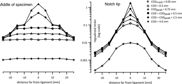
Figure 3.34 – Strain evolution under increased loading at different positions for strain hardening case ... 62
Figure 3.35 – Strain evolution under loading at different positions for strain softening case ... 62
Figure 3.36 – Strain evolution along ligament for specimen for strain hardening case ... 63
Figure 3.38 – Principal stress evolution with increased displacement for strain softening... 64 Figure 3.39 – Principal stress evolution with increased for strain hardening case ... 64 Figure 3.40 – Direct tension behaviour of TRCC [Hegger et al., 2004] ... 66 Figure 3.41 – Uniaxial tension behaviour of TRCC with different level of reinforcements ... 66 Figure 3.42 – Uniaxial tension behaviour of TRCC with different weft spacing ... 67 Figure 3.43 – Uniaxial tension behaviour of TRCC with different curing conditions ... 67 Figure 4.1 – FE discretization and boundary conditions ... 70 Figure 4.2 – Behaviour of coupling beam (CB1) with conventional concrete ... 71 Figure 4.3 – Behaviour of coupling beam (CB2) with PE fibres ... 71 Figure 4.4 – Behaviour of coupling beam (CB3) with PE fibres ... 72 Figure 4.5 – Behaviour of coupling beam (CB4) with twisted steel fibres ... 72 Figure 4.6 – Damage pattern for the case (CB3) ... 73 Figure 4.7 – Stress evolution under increased displacement for the diagonal bars in tension and compression ... 74 Figure 4.8 – Corresponding stress/strain on HPFRCC for large deformations... 74 Figure 4.9 – (a) r/c member; (b) multi-fibre elements and (c) section level ... 75 Figure 4.10 – Applied displacement history ... 75 Figure 4.11 – Constitutive law for: (a) concrete in compression and (b) cyclic behaviour of concrete 76 Figure 4.12 – Elastic-perfect plastic description in tension of: (a) HPFRCC and (b) steel reinforcement ... 76 Figure 4.13 – Numerical and experimental comparison without residual strength in compression, coupling beam (CB1) ... 77 Figure 4.14 – Numerical and experimental comparison with residual strength in compression, coupling beam (CB1) ... 77 Figure 4.15 – Numerical and experimental comparison for coupling beam (CB2), HPFRCC with PE fibres ... 78 Figure 4.16 – Numerical and experimental comparison for coupling beam (CB3), HPFRCC with PE fibres ... 78 Figure 4.17 – Numerical and experimental comparison for coupling beam (CB4), HPFRCC with twisted steel fibres ... 79 Figure 5.1 – Reinforcement cage detailing – Coupling beam... 82 Figure 5.2 – Reinforcement cage detailing – Lower block ... 82 Figure 5.3 – Reinforcement cage detailing – Upper block ... 83 Figure 5.4 – Coupling beam upgraded in three or two sides ... 84 Figure 5.5 – Coupling beam performance with different upgrading typologies ... 84 Figure 5.6 – (a) Load capacity of strengthened beam vs. thickness and (b) residual tensile strength of HPFRCC for different load capacities ... 85 Figure 5.7 – (a) Peak load drift of strengthened beam vs. thickness and (b) residual strength of HPFRCC for different drifts ... 86 Figure 5.8 – Boundary condition scheme ... 87 Figure 5.9 – Symmetric mesh ... 88 Figure 5.10 – Von Mises stresses at load 300 kN in the angular element ... 88 Figure 5.11 – Von Mises stresses in the bolts ... 89 Figure 5.12 – 3D view of the frame ... 90 Figure 5.13 – (a) UPN 400 Columns; (b) angular profiles and (c) HEB 400 beam ... 90 Figure 5.14 – Test rig fixed at base floor ... 91 Figure 5.15 – Schematic representation of setup under unidirectional loading. Flow of forces inside the frame; flow of oil in closed circuit ... 91 Figure 5.16 – Schematic representation of drift ... 92 Figure 5.17 – Cyclic displacement history ... 92 Figure 5.18 – (a) Reinforcement cage of the block and (b) reinforcement cage in the formwork ... 95 Figure 5.19 – Pouring and vibration of concrete ... 95
Figure 6.1 – Load displacement curve ... 102 Figure 6.2 – Diagonal cracking of the beam without any reinforcement... 102 Figure 6.3 – Diagonal failure mechanism of the beam... 103 Figure 6.4 – Load displacement curve specimen with longitudinal reinforcement ... 103 Figure 6.5 – Coupling beam with longitudinal reinforcement: (a) crack initiation and (b) crack propagation and failure of the specimen ... 104 Figure 6.6 – Strut and tie mechanism for coupling beam with longitudinal reinforcement ... 105 Figure 6.7 – Axial action effect on strut and tie mechanism ... 106 Figure 6.8 – Load displacement curve for monotonic and reversed cyclic loading on beams with complete reinforcement (CB-CR/A) and (CB-CR/B) ... 107 Figure 6.9 – Coupling beams with complete reinforcement under monotonic loading: (a) crack initiation and (b) multiple cracks formation ... 108 Figure 6.10 – Coupling beams with complete reinforcement under monotonic loading: (a) crack evolution and (b) failure of the specimen ... 108 Figure 6.11 – Coupling beams with both longitudinal and transverse reinforcement under cyclic loading (a) at 1% drift and (b) at 1.5% drift ... 109 Figure 6.12 – Coupling beams with both longitudinal and transverse reinforcement under increased cyclic displacements ... 110 Figure 6.13 – Coupling beams with complete reinforcement at final step of displacement... 110 Figure 6.14 –LVDT diagonal displacement measurements between for the specimen with both longitudinal and transverse reinforcement ... 111 Figure 6.15 – Comparison between LVDT diagonal displacement measurements between monotonic and cyclic test for the coupling beam with both longitudinal and transverse reinforcement ... 111 Figure 6.16 – Comparison between LVDT diagonal displacement measurements between two monotonic tests ... 112 Figure 6.17 – Three sided jacketing ... 115 Figure 6.18 – Load displacement curve for monotonic and reversed cyclic loading on beams strengthened with HPFRCC (CB-HP-0/A) and (CB-HP-0/B) ... 115 Figure 6.19 – Coupling beams strengthened with HPFRCC under monotonic loading at increased drift level ... 116 Figure 6.20 – Coupling beams strengthened with HPFRCC under monotonic loading: (a) deformations and cracking at final step and (b) delamination of HPFRRC ... 117 Figure 6.21 – Coupling beam strengthened with HPFRCC under cyclic loading: (a) visible crack on the surface of HPFRCC and (b) initiation of crushing under negative loading ... 118 Figure 6.22 – Coupling beam strengthened with HPFRCC under cyclic loading: (a) delamination and (b) buckling of bars under negative loading ... 118 Figure 6.23 – Coupling beam strengthened with HPFRCC under cyclic loading – manual remove of the HPFRCC layer at the end of test ... 119 Figure 6.24 – Load path of assigned pre-damage at 1% (SLS) ... 120 Figure 6.25 – Load displacement curve for monotonic and reversed cyclic loading retrofitted with HPFRCC at 1% pre-damage level (CB-HP-1/A) and (CB-HP-1/B) ... 121 Figure 6.26 – Coupling beam retrofitted with HPFRCC at 1% pre-damage level monotonic: (a) initiation of crushing and (b) delamination in one of the sides ... 122 Figure 6.27 – Coupling beam retrofitted with HPFRCC at 1% pre-damage level monotonic: (a) crushing failure and (b) visible distributed cracks ... 122 Figure 6.28 – Coupling beam repaired with HPFRCC at 1% pre-damage level – Failure of the beam ... 123 Figure 6.29 – Load path of assigned pre-damage at 2% (ULS) ... 124
Figure 6.30 – Load displacement curve for monotonic and reversed cyclic loading retrofitted with HPFRCC at 2% pre-damage level (CB-HP-2/A and CB-HP-2/B) ... 124 Figure 6.31 – Coupling beam repaired with HPFRCC (at 2% pre-damage level) at failure: (a) front and (b) rear ... 125 Figure 6.32 – Coupling beam retrofitted with HPFRCC at 2% pre-damage level – Failure of the beam ... 126 Figure 6.33 – Coupling beam strengthened with textile reinforce cementitious composite... 127 Figure 6.34 – Coupling beam strengthened with TRCC monotonic – Crack initiation and propagation under increased displacement ... 128 Figure 6.35 – Coupling beam strengthened with TRCC monotonic – Multiple cracks initiation and propagation under increased displacement ... 128 Figure 6.36 – Coupling beam strengthened with TRCC under cyclic displacement – Crack evolution under increased reversed displacements ... 129 Figure 6.37 – Failure of the coupling beam strengthened with TRCC under cyclic displacements ... 129 Figure 6.38 – Comparison of load drift displacement curves for conventional coupling beams ... 130 Figure 6.39 – Comparison of the experimental results under monotonic loading considering different strengthening/retrofitting techniques ... 131 Figure 6.40 – Comparison results of cyclic tests with of reference coupling beam with respect to the strengthened beams with HPFRCC or TRCC ... 132 Figure 6.41 – Comparison between cyclic tests of coupling beams retrofitted with HPFRCC ... 132 Figure 6.42 – Energy dissipation of coupling beams under monotonic loading ... 133 Figure 6.43 – Energy dissipation at fixed levels of drift, coupling beams under monotonic loading .. 134 Figure 6.44 – Energy dissipation for each cycle for all the tests ... 134 Figure 6.45 – Comparison of energy dissipation for each cycle - control specimen and coupling beam strengthened with TRCC ... 135 Figure 6.46 – Comparison of energy dissipation for each cycle – control specimen and coupling beam strengthened with HPFRCC ... 135 Figure 6.47 – Comparison of energy dissipation for each cycle – control specimen and coupling beam retrofitted with HPFRCC (with 1% pre-damage) ... 136 Figure 6.48 – Comparison of energy dissipation for each cycle – control specimen and coupling beam retrofitted with HPFRCC (with 2% pre-damage) ... 136 Figure 6.49 – Energy dissipation ratio for coupling beams under cyclic loading both strengthened and retrofitted ... 137 Figure 6.50 – Energy dissipation ratio for coupling beam under cyclic loading strengthened with TRCC... 137 Figure 6.51 – Energy dissipation ratio for coupling beam under cyclic loading strengthened with HPFRCC ... 138 Figure 6.52 – Energy dissipation ratio for coupling beam (pre-damaged 1%) under cyclic loading retrofitted with HPFRCC ... 138 Figure 6.53 – Energy dissipation ratio for coupling beam (pre-damaged 2%) under cyclic loading retrofitted with HPFRCC ... 139 Figure 6.54 – Axial displacement measured from two instruments for the specimen (CB-HP-0/B) . 140 Figure 6.55 – Axial displacement measured from two instruments for the specimen (CB-HP-0/B) . 140 Figure 6.56 – Axial displacement measured from two instruments for the specimen (CB-HP-1/A) . 141 Figure 6.57 – Axial displacement measured from two instruments for the specimen (CB-HP-1/A) . 141 Figure 6.58 – Comparison between average axial displacement under monotonic and cyclic displacements ... 142 Figure 6.59 – Comparison between average axial displacement under monotonic and cyclic displacements ... 142 Figure 6.60 – Load displacement response of coupling beam with both longitudinal and transverse reinforcement ... 143 Figure 6.61 – Load displacement response of coupling beam strengthened with HPFRCC ... 143
Figure 7.5 – Coupling beams employed for numerical analysis ... 150 Figure 7.6 – Upgrading of coupling beams in three sides: (a) with r/c jacketing and (b) HPFRCC ... 151 Figure 7.7 – Base shear for the wall without any strengthening (3 storeys) ... 152 Figure 7.8 – Base shear for the wall strengthened with HPFRCC layer (3 storeys) ... 153 Figure 7.9 – Base shear for the wall strengthened with r/c jacketing (3 storeys) ... 153 Figure 7.10 – Base shear for the wall without any strengthening (5 storeys) ... 154 Figure 7.11 – Base shear for the wall strengthened with HPFRCC layer (5 storeys)... 155 Figure 7.12 – Base shear for the wall strengthened with r/c jacketing (5 storeys) ... 155 Figure 7.13 – Shear force at base for 5 storeys wall ... 157 Figure 7.14 – Effect of upgrading a single coupling beam at different storey ... 158 Figure A.1 – UPN 400 column, 2 pieces ... 165 Figure A.2 – UPN 400 column, 2 pieces ... 165 Figure A.3 – Angular profile, 2 pieces ... 166 Figure A.4 – HEB 400 profile, 1 piece ... 166 Figure A.5 – (a) closed loop of jack; (b) and (c) different views of pump ... 167 Figure A.6 – Load transfer from bar to the specimen ... 167 Figure A.7 – (a) fixing of specimen and (b) steel plate to guarantee planarity and provide sliding boundary condition ... 168 Figure A.8 – (a) Jack utilized and (b) Fixing of the jack ... 168 Figure A.9 – Compression load cell with capacity 400 kN ... 169 Figure A.10 – Data acquisition ... 169 Figure A.11 – LVDT employed with different maximum capacities: (a) 150 mm; (b) 25 mm and (c) 10 mm ... 170 Figure A.12 – Gefran PY2 LVDT position for local measurements (a) front and (b) rear face ... 170 Figure A.13 – Acquisition controller ... 170 Figure A.14 – Tensile testing machine ... 171 Figure A.15 – Uniaxial test results of 2 bars 6: stress vs. strain ... 172 Figure A.16 – Uniaxial test results of 2 bars 8: stress vs. strain ... 172 Figure A.17 – Uniaxial test results of 2 bars 14: stress vs. strain ... 173
L
IST OF TABLES
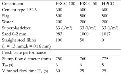
Table 3.1 – Mix design and fresh state performance of the employed cementitious composite ... 30 Table 3.2 – Slag chemical composition ... 30 Table 3.3 – Mixing protocol for cementitious composites ... 31 Table 3.4 – Aggregate size coefficient ... 51 Table 3.5 – Input parameters of constitutive relationships for numerical modelling ... 55 Table 4.1 – Material parameters used for numerical modelling of coupling beams ... 71 Table 5.1 – Identification notation for each tested specimen ... 94 Table 5.2 – Conventional concrete mixture ... 96 Table 5.3 – TRCC mixture ... 98 Table 5.4 – Mixing protocol for TRCC matrix ... 98 Table 6.1 – Total energy dissipation for the tested specimens under monotonic loading ... 133 Table 7.1 – Resisting shear force and required longitudinal reinforcement for three storeys wall... 148 Table 7.2 – Resisting shear force and required longitudinal reinforcement for five storeys wall ... 148 Table 7.3 – Three storeys ... 150 Table 7.4 – Five storeys... 150 Table 7.5 – Efficiency factor of 5 storeys wall ... 158 Table A.1 – Concrete strength in compression ... 171 Table A.2 – Uniaxial tension of steel reinforcement ... 172
1
1 Introduction
Progressive deterioration of existing reinforced concrete structures is highlighting an urgent need for repairing and strengthening structural elements in order to make the structure to perform as intended or even anticipated or simply to make it complying with updated and, not seldom, more rigorous and stringent design provisions. In this framework, the use of advanced cement based materials has become an attractive solution within the research community, particularly for rehabilitation of slender beams and columns e.g. [Meda, et al., 2007; Martinola, et al., 2010; Shin et al., 2011], as these materials are highly damage tolerant and can hence provide the required performance and ease of application. In this thesis the use has been investigated of advanced cement based materials specifically i.e. High Performance Cementitious Composites (HPFRCC) and Textile Reinforced Cementitious Composites (TRCC) as a upgrading/repairing for coupling beams in order to improve, as obviously, the performance of damaged and/or poorly designed coupling beams in terms of strength, ductility and energy dissipation capacity but also to recover, as possible, the “coupling effect” on the behaviour of the shafts. It is worth remarking, as peculiar features of the use of these materials, that they do not require a minimum cover in order to comply with durability constraints. Moreover, it is possible to align in the case of HPFRCCs the fibres along the expected loading direction by controlling the fresh state performance and casting process and in case of TRCCs by placing the textile fabric according to the desired direction.
1.1
Thesis outline
This thesis is structured in eight chapters, starting with the current chapter describing the organisation of the research work.
Chapter two is mainly concerned with engineering motivation based on literature review that stands behind this research, with reference to the historical background of coupling beams up to now, and highlighting the importance of upgrading such elements.
Chapter three deals with the choice of fibre reinforced cementitious composite as upgrading/retrofitting solution, with attention on tensile characterization using a novel indirect technique known as “Double Edge Wedge Splitting” test. It is explored the effectiveness of using both non-destructive and destructive techniques to correlate the fibre
related parameters to the tensile behaviour. The robustness of “crush-crack” damage model with reference on modelling the fibre reinforced cementitious composites is emphasized. Chapter four is dedicated on modelling the coupling beams with reference to experimental results chosen from the literature review, consisting either from conventional reinforced concrete or high performance fibre reinforced cementitious composites. To this purpose is employed the crush “crack damage” model which would allow a very detailed analyses of the structural element. As well a simpler modelling approach based on multi-fiber Timoshenko beam element is assessed.
Chapter five is mainly concerned on design of the experimental campaign for testing with reference to coupling beams which involved the preparation of the specimens and the application of both retrofitting techniques either HPFRCC or TRCC. To this purpose a detailed description of the testing rig is also provided.
Chapter six presents the experimental investigations of coupling beam tests that were either non upgraded/retrofitted or upgraded/retrofitted. It is assessed the use of HPFRCC and TRCC as beneficial solution on upgrading/retrofitting coupling beams under monotonic and reversed cyclic displacements. Design equations are evaluated provided by strut and tie method and [fib Model Code 2010] provisions with reference to experimental tests. And last it is employed the fibre Timoshenko beam to model a couple of cases of coupling beams at issue.
Chapter seven highlights the importance of upgrading the coupling beams on the overall behaviour of the shear wall, through numerical analysis.
Chapter eight provides the main conclusions of this research work and finally remarks the future perspective needs.
2
2 Literature Review
2.1
Coupling beams
Coupling beams as interconnection of shear walls in earthquake-resistant structures have to be designed with the purpose of transmitting the lateral forces resulting from earthquake excitation between the different shafts the wall consists of. Moreover, since the shear walls, could be subjected as well to strong lateral load produced by winds or differential downward settlement of soils (Figure 2.1) the coupling beams must be able also to resist stresses arising from the aforementioned situations while undergoing the resulting deformations. The coupling beams as force transfer elements between shafts play a crucial role on global wall performance. This capacity of transferring forces has to be guaranteed up to high levels of deformations, to allow for the development of plastic hinge at the base of the wall. In practice, achieving a realistic transfer of force, as most of design codes are promoting, requires careful arrangement of the reinforcement, which may result in details difficult to be executed. It is vital that coupling beams must be able to undergo large inelastic deformation under load reversals without a significant reduction on stiffness, load bearing and energy dissipation capacity. When walls are subjected to lateral load, the shear transfer in coupling beam result in tension in one wall, and in compression in the other wall. This coupling effect provides additional moment resistance for the entire wall system, with respect to uncoupled systems as illustrated in (Figure 2.2), because of increased lever arm between the resultants of tensile and compressive stresses which can take profit of the entire length of the wall cross-section.
(a) (b)
Figure 2.1 – Wall behaviour (a) under lateral load and (b) soil settlements
downward settlement lateral
(a) (b)
Figure 2.2 – Resisting mechanism of (a) coupled and (b) uncoupled wall systems
R T(or C)lw (2.1)
R c t (2.2)
The observed brittle failure of coupling beams of Mt. McKinley apartments after the 1964 Alaska earthquake, confirmed that coupling beams should be carefully designed to provide effective link between the walls. Since then, many studies have been carried out to enhance the ductile behaviour of coupling beams considering the geometrical constraints. It has been indicated that traditional principles for the beam design are not appropriate for deep coupling beams. The very first and the most innovative reinforcement arrangement for the coupling beam to avoid brittle failure was proposed by Paulay in 70’s. It consisted of diagonal reinforcement to improve the diagonal tensile failure under cyclic loading, as suggested by crack patterns. Lateral confinement of diagonal bars by stirrups was also recommended to avoid buckling under large lateral loads.
Figure 2.3 – Failure of coupling beams due to earthquake Alaska (Alaska Digital Archive)
Other researches in later studies [Taassios et al., 1996; Galano et al., 2000; Fortney et al., 2008] tested coupling beams with different aspect ratios (equal to 1 and 0.75 respectively) in
compressive force tensile force M1 M2 lw tensile force compressive force lw Vt Vc V t Vc
order to assess the effectiveness of reinforcement layouts other than bi-diagonal. The proposed and tested reinforcement arrangements are sketched in (Figure 2.4); (a) conventional; (b) bi-diagonal; (c) rhombic; (d) short dowels and (e) long dowels. It has been reconfirmed the overall superior performance of diagonally reinforced coupling beams among all layouts. However, it has been observed that also rhombic layout would be an interesting alternative to be considered due to its simplicity in detailing, since it exhibited less stiffness degradation than conventional layout.
Figure 2.4 – Various reinforcing configurations for coupling beams
During the last decade several promising studies have been conducted aimed at improving the structural behaviour of coupling beams using embedded structural element such as I-beams, plates and tubes [Harries, 1995; Lam et al., 2004; Gong et al., 2001]. Recently HPFRCC has been suggested as an alternative replacement of the traditional concrete, allowing the reinforcement reduction and a simplified detailing. Such an alternative has also been shown to dramatically improve energy dissipation capacity, besides highlighting a simpler constructability [Canbolat et al., 2005; Lequesne et al., 2011; Park et al., 2011]. The experimental investigations by [Canbolat et al., 2005] are taken as reference for model calibration in forthcoming chapters of this thesis.
[ACI 318-08] has “relaxed” the strict provisions of [ACI 318-05], which required diagonal bars confined with transverse ties, and has allowed the full section confinement and the elimination of the diagonal reinforcement. Experimental tests by [Naish et. al 2009; 2013] have in fact shown that full transverse section confinement would provide even better performance of the longitudinally reinforced coupling beams in terms of strength and ductility compared to the diagonally reinforced ones. Moreover, it has been demonstrated by experiments that also lateral restraint that could be attributed to slabs would provide slight improvement on performance of coupling beams.
To have efficient performance of the coupled shear wall systems, it is important to guarantee a well balanced degree interaction between coupling beams and wall units, since over coupling would induce large axial forces and bending moments in wall shafts and would be characterized by highly stressed compression corners. Hence, coupling beams should be designed to yield prior to the shear walls in order to benefit from their ductility, which under severe earthquakes would dissipate large amount of energy.
a)
b) c)
e) d)
While designing coupled shear walls, four basic failure mechanisms should be considered for coupling beams:
- Flexural failure (common for beams with span-to-depth ratio >4);
- Diagonal shear failure in tension or compression (common for beams with span-to-depth ratio <4);
- Shear sliding; - Strong coupling.
Most of the surveyed studies suggest that the common failure mode of coupling beams is characterized by brittle failure in shear rather than in bending, due to their relatively low span to depth ratio (<3) caused by inescapable geometrical constraints.
2.1.1 Steel/composite coupling beams
Other approaches have been proposed to overcome the difficulty of execution of concrete coupling beams. In an early study [Paparoni, 1972] reported on reinforced coupling beams containing encased structural “I” steel profiles. The results suggested that this type of coupling beams can exhibit intermediate ductility between conventionally reinforced and diagonally reinforced member. Another alternative has been also studied [Harries, 1995], consisting of the embedment of the steel “I” profile into concrete shear wall. From these investigations it has been shown that proper embedment of the relatively shallow-depth
wide-flange steel profiles could provide significant improvement of the cyclic reversed
response of the coupling beams. A combination of two preceding techniques studied by [Gong et al., 2001] is another alternative proposed, which would provide additional capacity. Regardless that these type of coupling beams provide an excellent performance, the main obstacle that have been faced in practice and put in stand such type of beams is that the embedment of steel profile into either the coupling beam or the wall interferes with conventional reinforcement detailing, and consequently increases the labour cost.
2.1.2 HPFRCC coupling beams
[Yun et al., 2008] investigated the cyclic behaviour of short coupling beams. Three beams were tested with two different variables considered, the reinforcing arrangements and the mortar composition. All the beams have same geometry with length 600 mm, height 600 mm and width 200 mm (span-to-depth ratio equal to 1), and are transversally reinforced with
stirrups 6 spaced at 150 mm with yield strength 291 N/mm2. The first coupling beam was
reference one (CB1) made of conventional concrete and reinforced with rhombic and longitudinal reinforcement, the second case (CB2) was identical to the previous one as illustrated in (Figure 2.5), but instead of conventional concrete, high performance fibre reinforced cementitious composite (HPFRCC) was used. The last beam (CB3) had the same matrix as (CB2) but did not have any rhombic reinforcement, being solely reinforced
longitudinally with 216 with yield strength equal to 474 N/mm2. The employed HFRCC
was composed by hybrid fibre reinforcement consisting of 0.75% by volume ultra-high molecular weight polyethylene (PE) fibres (with length equal to 12 mm and diameter equal to 0.012 mm), and 0.75% twisted steel fibres by volume (with length equal to 32 mm and diameter equal to 0.4 mm) [Yun et al., 2007]. The reported compressive and tensile strength
were between 44 to 57 N/mm2, and 3.02 to 3.53 N/mm2 respectively, with strain capacity up
to 3%. The beam was connected with two stiff blocks: one serves to apply the load and the other to maintain the specimen fixed. Two jacks were used to maintain the upper block
planar to the lower one, and one actuator was used to apply cyclic loading. The test setup is illustrated in more details in (Figure 2.6).
(a) (b)
Figure 2.5 – Specimen geometries and reinforcement details (unit mm): (a) (CB1) and (CB2) specimens; and (b) (CB3) specimen [Yun et al., 2008]
Figure 2.6 – Test setup [Yun et al., 2008]
(a) (b) (c)
Figure 2.7 – Cyclic behaviour of specimen: (a) (CB1); (b) (CB2); and (c) (CB3) [Yun et al., 2008] From the hysteretic response of beams (CB1) and (CB2) the significance has been highlighted of using HPFRCC by observing increase in strength from 704 kN to 865 kN, and significant increase on deformability which was associated with multiple crack observed on the specimens. Instead the (CB3) confirms that using HPFRCC would allow simplified reinforcement arrangement while still providing better behaviour with respect to beam (CB1).
A wide experimental campaign has been performed in the last decade on the behaviour of coupling beams and shear walls at University of Michigan [Canbolat et al., 2005; Hung, 2010;
Athanasopoulou, 2010; Lequesne, 2011]. Several variables have been considered to have better understanding of the behaviour of the coupling beams. Moreover, the use has been explored of a new generation of cementitious composites with moderate volume fraction of fibres up to 2%. In the following the work will be presented performed by [Canbolat et al., 2005], which highlights the significance of using HPFRCC to provide a reduced labour work for reinforcement detailing while guaranteeing a better structural performance. The geometry of the beam was the same for all specimens, with span-to-depth ratio of 1 (600x600 mm), and width of 200 mm or 150 mm. The specimen consists of two stiff blocks connected by the coupling beams, which would serve for fixing of the specimen to the base floor and connection of the actuator to apply the quasi static load at mid-span of the beam, as illustrated in (Figure 2.8).
Figure 2.8 – Test setup employed [Canbolat et al., 2005]
The first specimen was a r/c control specimen, designed and detailed accordingly to ACI building code, suggesting diagonally reinforcement; each diagonal has 413 bars confined
with stirrups 6 spaced at 120 mm, steel yield strength was 450 N/mm2 and concrete
compressive strength at test day was 41 N/mm2. The second specimen was made of
HPFRCC with ultra-high molecular weight polyethylene (PE) fibres at 2% volume fraction (with length equal to 13 mm and diameter equal to 0.038 mm), and reinforced only with
longitudinal 315 bars and stirrups 6 spaced at 150 mm in order to evaluate the
effectiveness of addition of fibres. The third specimen was made with the same HPFRCC as
the second one but the diagonal reinforcement was simplified adopting only 216 bars for
each diagonal with no transverse stirrup. The fourth specimen had rhombic reinforcement arrangement to provide easier handling, and was made of FRCC with twisted steel fibres at 1.5% volume fraction (with length equal to 30 mm and diameter equal to 0.3 mm). On the
testing day the compressive strength was between 57 and 63 N/mm2, and tensile strength
equal to 3.1 and 5.5 N/mm2 up to 0.5% strain capacity, for the HPFRCC with PE and
twisted steel fibres respectively.
Figure 2.9 – Uniaxial tensile response of specimen with polyethylene
Figure 2.10 – Geometries and the different reinforcement details [Canbolat et al., 2005]
From the experimental results shown in (Figure 2.11) it has been highlighted that using PE fibres would allow to remove the diagonal bars and have better performance in load bearing capacity, which increased from 470 kN to 600 kN. Nevertheless, the drift capacity was strongly reduced from 4% to 1.8% with a simplified arrangement. Which indicated a lower energy dissipation. Alternatively the addition of diagonal bars in the specimen with PE fibres, even with simplified arrangement up to 800 kN achieved at 2.5% of drift also guaranteed the same level to be maintained up to 4% drift. Anyway a strong asymmetric behaviour was measured on reversed loading due to compressive buckling of bars. The fourth specimen, using the bent diagonal bars and twisted steel fibres showed a very stable energy dissipation and the same strength capacity as specimen 3. In the following chapter four these experimental evidences have been used as reference on design and modelling coupling beams
2.2
Design and modelling of the coupling beams
When designing coupling beams whose geometry is of such that they feature a low (<3) span-to-depth ratio; the beam model that section remain plane cannot evidently be held true. As shown by theoretical studies on the failure behaviour of the coupling beams, after cracking the beam behaves as a truss. This suggests the strut and tie approach to be adopted for designing the elements at issue. The first one equation has been proposed by [Park et al., 1975] to predict the maximum capacity of diagonally reinforced coupling beams with aspect ratio less than 2. The proposed approach could well predict the test results; that it strictly assumes the failure is governed by diagonal steel yielding and it does not take into account the contribution of concrete or transverse reinforcement. Where is the inclination angle of the diagonal bars.
sd
f
ysin
(2.3)[Subedi, 1991] did a step further by proposing a mathematical model to assess the ultimate load capacity by distinguishing between two different failure modes, flexural and shear. Nowadays, several different models are proposed, based on the same approach by considering different combinations of strut and tie mechanisms depending on the reinforcing configurations [Jang et al., 2004], yet the main obscurity remain the definition of the strut cracking angle requiring engineering intuition. Most of the equations would serve to calculate the maximum shear capacity of the coupling beams related to different failure modes, but would not give any information about the deformation capacity, which is of the equal importance, since coupling beams are required and expected to dissipate a large amount of energy under large lateral loadings prior to failure.
A sound method has been developed [Baczkowski, 2007] to predict the load-deflection behaviour for both r/c and steel fibre reinforced concrete (SFRC) deep coupling beams based on experimental tests. In this method are combined the strut and tie model, fracture mechanics and energy principles, the latter one being used for determination of the cracking angle in order to guarantee physical soundness. However, from comparisons between the model and experiments a good prediction of maximum load bearing capacity was observed but the loading paths were not described equally well.
From some of the aforementioned issues highlighted above, the whole (nonlinear) behaviour is hence of interest and not only the maximum load bearing capacity. Since its introduction,
performance based design has become a common tool for structural engineers to evaluate the nonlinear behaviour (Force-displacement or Moment-rotation) for a given structure. In this technique it is necessary to introduce the nonlinear response for each member by force-displacement envelopes, known as backbone curves, in specific zones to evaluate the global structural response. This modelling technique has been adopted [Brena et al., 2009 and Lequesene, 2011] to describe the behaviour of r/c and HPFRCC coupling beams, and it provided realistic description. However, since the definition of a force component at corresponding displacement is required, this approach becomes cumbersome to be used in everyday practice. Evidently the calibration of these approaches requires a huge number of experimental tests and that is obvious with observations in the literature on increased experimental database. However, this data should be consistent with real behaviour of the coupling beams which in experiments may be not well captured, as for instance, with reference to the clear definition of boundary conditions, interaction of different contributions as shear, flexural and axial deformation etc..
Indeed finite element method is widely used for modelling different structural members, and some attempts have been performed very recently by few authors to model coupling beams. However, the simplified assumptions are still necessary to be made, and require calibration of parameters to relevant experimental evidences.
[Zhao et al., 2004] In a recent study four r/c specimens scaled at 1:2 were tested under monotonic loading with different aspect ratios namely (MCB1, l/h=1.17), (MCB2, l/h=1.4), (MCB3, l/h=1.75) and (MCB4, l/h=2.0). All the beams were similarly reinforced both with longitudinal and transverse reinforcement ratio, equal to 0.5% and 1.07% respectively. Below in (Figure 2.12) the specimen geometry and tests setup are shown. They used FE to model the nonlinear behaviour of coupling beams under monotonic loading, providing relatively good agreement between experimental investigations and numerical approach adopted (Figure 2.13).
(a) (b) _ Figure 2.12 – (a) Specimen (MCB1) and (b) test setup
Figure 2.13 – Comparison between experimental investigation and numerical results: (a) (MCB1); (b) (MCB2); (c) (MCB3) and (d) (MCB4)
They also performed a parametric study on the effects of boundary conditions on the nonlinear behaviour, highlighting the great importance of the degree of axial constraint since it contributes on increase of strength and ductility (Figure 2.14).
Figure 2.14 – Effects of axial restraining on specimen (MCB1) numerically assessed
2.3
Retrofitting/strengthening of structural elements
Progressive deterioration of existing r/c structures is highlighting the urgent need of retrofitting and strengthening structural elements in order to make the structure to perform as intended or anticipated or simply to make it complying with updated and, not seldom, more rigorous and stringent design provisions. Because of this, upgrading or retrofitting of existing structures is becoming an important field of study both from economical and environmental aspects. Several viable retrofitting/strengthening techniques are available nowadays, as listed below.
The most conventional method is by jacketing existing structural element with an additional reinforced concrete layer; due to durability constraints these technique requires sectional enlargement between 60-70 mm due to presence of steel reinforcement [fib Bulletin 24, 2003].
Another technique is using steel plates bonded either with epoxy based adhesives to the existing element. The main problem concerning these techniques is due to differences in stiffness and plastic deformations between substrate and adhesive materials which can cause stress concentration.
Epoxy bonded Fibre Reinforced Polymer (FRP) sheets has gained increased popularity, due to numerous attractive features [Triantafillou et al., 2005] (i.e. high specific strength, corrosion resistance, speed of application and very low thickness). However several drawbacks are also observed such as high cost of resins, hazard for the manual worker due to their toxic solvent content, non-applicability on wet or moist surface and at temperatures lower than 10°C, lack of vapour permeability which may lead to durability problems [Emmons et al., 1994] and incompatibility between adherent and organic binders which do not suit the poor concrete surfaces and could cause debonding of FRP laminates. As consequence of high bond achieved by inorganic binders, high shear stresses at interfaces between the old concrete and the composite are developed, which may cause the loss of repair action and may induce an essential damage to the element.
To overcome these drawbacks, cement based materials have attracted a great attention; the main concept is to substitute the FRP sheet with a textile mesh and to use instead of resins, an inorganic binder to penetrate it.
The reinforcement mechanism is changed as the organic binders are more ductile than carbon or glass fibres. Instead for cement matrix the failure strain in tension is lower (Figure 2.15) making the interaction between fabric and composite to become more effective due to crack bridging and allows the redistribution of forces to other sections [Peled, 2003]. The bond between the cementitious composite and substrate is lower than the one achieved with organic binders. These two features, the crack formation and lower bond, would lead to reduced interface stress concentrations.
(a) (b)
Figure 2.15 – Categories of Textile reinforced composites (a) failure of fibres and (b) failure of matrix [Wiberg, 2003]
2.4
HPFRCC as strengthening material
2.4.1 Flexural strengthening
The use of High Performance Fibre Reinforced Cementitious Composites (HPFRCCs) has become an attractive solution within the research community, particularly for rehabilitation
of slender beams and columns [Martinola et al., 2010; Meda et al., 2007; 2009]. Four point bending true scale testing have been performed on 4.55 m long, and 0.5 m deep beams to study both retrofitting and strengthening using tensile strain hardening material [Martinola et al., 2010]. Before applying the jacket the surfaces were sandblasted, and then a 40 mm thin HPFRCC layer was applied. The employed HPFRCC contained 2.5% by volume steel micro-fibres having a length of 12 mm and a diameter of 0.18 mm, and exhibited an almost elastic
plastic behaviour in tension with 11.8 N/mm2 tensile strength and strain capacity equal to
0.47%. Four cases were considered, a reference beam with 216 longitudinal reinforcement
and 8 spaced at 150 mm stirrups to avoid shear failure; two beams having the same
reinforcement arrangement but the one upgraded and the other was pre-damaged up to longitudinal reinforcement yielding, and was retrofitted with HPFRCC. The final beam had no reinforcement (neither longitudinal nor transverse reinforcement) but was strengthened with HPFRCC.
Figure 2.16 – (a) Geometry and loading of the specimen and (b) jacketing with HPFRCC [Martinola et al., 2010]
Figure 2.17 – Behaviour of the tested beams [Martinola et al., 2010]
From the experimental results it has been observed (Figure 2.17) that the retrofitted and strengthened beam has exhibited a load bearing capacity as higher as twice the one of the reference beam. Moreover an increase of stiffness was also evident, that could be due to the section enlargement.
(a) (b)
Figure 2.18 – Numerical results of the beam: (a) without jacketing and (b) with HPFRCC jacketing [Martinola et al., 2010]
From nonlinear FEM analysis it is evident that the behaviour of conventional r/c beam could well predict the experimental investigations, while regarding the r/c beam strengthened with HPFRCC the analysis has shown an overestimation on overall performance of the beam (Figure 2.18). That could be related to question of tensile identification tests on small specimens representative to the behaviour in the retrofit layer. Not only, in the analysis was considered perfect bond between the HPFRCC layer and concrete substrate which in reality could undergo some debonding, which entail identification of interface interaction between the two different materials .
Regarding numerical models, as a matter of fact reliable approaches to predict the behaviour of HPFRCC coupling beams and transfer the garnered knowledge into reliable design prescriptions are so far lacking, also because of this still ongoing evolution of code prescriptions concerning structural applications of Fibre Reinforced Concrete.
2.4.2 Shear strengthening
[Maringoni et al., 2011] investigated the use of different high strength jackets with or without combination of steel meshes to provide shear strengthening for slender beams. Four beams with effective span of 2.5 m and the height of 450 mm were tested in 4 point bending test (Figure 2.19). Three of them were upgraded with different configurations as sketched in (Figure 2.20). To provide a good bond between existing substrate and new composite layer, the surface was sandblasted to provide an average roughness of about 1 mm. The great potential of using advanced cement based for upgrading was demonstrated with about double increase in strength and stiffness, by using a jacket with thickness 50 mm. To this purpose two different typologies of HPFRCC were used, one was self levelling matrix that could be casted directly in the formwork, the other was thixotropic that could be applied directly on the surface. In this work the beam was made with concrete class C20/25; the bars
had a yield strength of 518 N/mm2, whereas the HPFRCC contained 3.9% fibres by volume
content (with length 15 mm and diameter 0.175 mm) and tensile strength equal to 6 N/mm2
and 5 N/mm2, for self levelling and thixotropic HPFRCC; a steel wire mesh of 2 spaced at
25 mm with yield strength 550 N/mm2 was also used. The beam (B) was strengthened with
self levelling HPFRCC jacket 50 mm thick, and inside it has been inserted the U shaped stainless steel mesh. The other two beams (D) and (E) at the intrados were upgraded with self levelling HPFRCC and on the lateral surface with thixotropic HPFRCC. Also in these
cases were placed the U shaped stainless steel mesh, in beam (D) for sake simplicity on application the U shaped mesh was applied up to a height of 20 cm on lateral surfaces.
Figure 2.19 – Geometry and testing of the beam [Maringoni et al., 2011]
Figure 2.20 – Performance of strengthened beam with different configurations [Maringoni et al., 2011]
2.5
Textile reinforced cementitious composites TRCC as
retrofitting/strengthening material
2.5.1 Shear strengthening
Several studies have confirmed the effectives of using the Textile Reinforced Cementitious Composites (TRCC) systems applied to concrete structural elements in order to improve their capacities such as flexural behaviour of beams and slabs [Larrinaga, 2010; Weiland et al., 2006], behaviour of columns under axial loading [Al-Jamous et al., 2006]. [Triantafillou et al., 2005] tested in four point bending 6 beams, with length of 2.5 m and section 15x30 cm, as illustrated in (Figure 2.21a-b). The beams were poorly designed in shear. Four beams were tested in monotonic and two in cyclic loadings. The concrete strength was reported to be
30.5 N/mm2, and average yield strength of longitudinal and transverse reinforcement equal
to 575 N/mm2 and 275 N/mm2 respectively. For jacketing unwoven carbon textile was used
with mass 168 gr/m2 and with nominal thickness of each layer 0.047 mm. In both directions
the textile provides strength of 3350 N/mm2 and elastic modulus 225 GPa.
The four specimens that were tested monotonically: specimens were denoted as follows (C) was a control specimen without any strengthening, (M2) beam was strengthened with two layers of mortar based jacketing over shear span, (R2) beam has same strengthening instead but instead of mortar a resin was used, and (M2-s) has spirally applied strips in (Figure
2.21c). Two further specimens were tested under cyclic loading; a reference specimen (R1) identical to (R2) and (M1) identical to (M2).
Figure 2.21 – Geometry and loading of the beam reinforced with TRCC [Triantafillou et al., 2005]
Figure 2.22 – Behaviour of beams under monotonic and cyclic loading with different configurations of TRCC [Triantafillou et al., 2005]
From the results it is evident (Figure 2.22) that in strengthened beams (M2), (R2), (R1) and (M2-s), the failure mechanism was changed from shear to flexural with respect to reference beam. The results of cyclic tests indicated anyway that for beam (M1) shear strength increased but failure mode did not change.
![Figure 2.22 – Behaviour of beams under monotonic and cyclic loading with different configurations of TRCC [Triantafillou et al., 2005]](https://thumb-eu.123doks.com/thumbv2/123dokorg/7514822.105545/47.892.235.703.538.980/figure-behaviour-monotonic-cyclic-loading-different-configurations-triantafillou.webp)
![Figure 2.27 – Coupling beam performance before and after repair with CFRP [Riyaz et al., 2007]](https://thumb-eu.123doks.com/thumbv2/123dokorg/7514822.105545/50.892.130.722.519.716/figure-coupling-beam-performance-repair-cfrp-riyaz-et.webp)
![Figure 2.31 – Influence of the volume fraction content on the compression [Fanella et al., 1985]](https://thumb-eu.123doks.com/thumbv2/123dokorg/7514822.105545/54.892.144.728.897.1081/figure-influence-volume-fraction-content-compression-fanella-et.webp)


![Figure 3.28 – Numerical and experimental comparison for strain softening and hardening specimens for FRCC- FRCC-100 01 2 3COD [mm]0246810n [N/mm2]5B experimental](https://thumb-eu.123doks.com/thumbv2/123dokorg/7514822.105545/84.892.202.641.729.1034/figure-numerical-experimental-comparison-softening-hardening-specimens-experimental.webp)