Politecnico di Milano
Scuola di Ingegneria Industriale e dell’Informazione
Corso di Laurea Magistrale in Ingegneria Informatica Dipartimento di Elettronica, Informazione e Bioingegneria
A Model-based Graphical Designer for
Engineering Forensic-ready Systems
Relatore: Prof. Luciano BARESI Correlatore: Dr. Liliana PASQUALE
Tesi di laurea di:
Abstract
Nowadays there is an increasing trend towards embedding computational capab-ilities into devices to make them effectively communicate and perform useful tasks. This is the so-called pervasive computing environment and, since software systems are becoming more pervasive, there is the need of protecting such systems from incid-ents perpetrated by malicious individuals. Unfortunately, it is not feasible to prevent all possible incidents because they are increasing in number and complexity and this is the reason why a digital investigation should be performed to explain how an in-cident occurred and who was responsible for it. A forensic-ready system would help in the investigation minimising the costs and using the relevant digital evidence. In particular, such system is able to monitor data that can be useful to satisfy or refuse an incident hypothesis before it happens. The objective of the thesis is developing a graphical designer for engineering forensic-ready system that helps describing the environment and some incident hypotheses that may occur within the environment. These descriptions are then used by an external tool that generates rules to pre-serve the relevant data for the investigation. The graphical designer aims to solve some limitations of the tool concerning usability, correctness of the descriptions and reusability of the software. To address these problems, I use the Model-Driven En-gineering (MDE) approach which allows substituting code with meta-models and specifically it ensures correction of the models based on the meta-model by design. I use the frameworks Eclipse Modeling Framework (EMF) for the creation of the meta-model and Graphical Modeling Framework (GMF) to build a graphical designer that facilitates the representation of the environment and incident hypotheses addressing the usability limitation. Finally, to foster reusability, the graphical designer was
implemented as an Eclipse plugin. The approach has been evaluated by describing the environment and the incident hypotheses of three scenarios inspired by existing digital forensic corpora.
Sommario
Nella società odierna si sta verificando una crescita verso l’integrazione di capacità computazionale nei dispositivi elettronici per facilitarne la comunicazione ed eseguire operazioni utili. Questo tipo di integrazione costituisce l’aspetto caratterizzante dei sistemi pervasivi. La crescita nell’utilizzo di sistemi pervasivi sta anche rendendo più necessario proteggere questi sistemi da incidenti a scopo criminale. Sfortunatamente, prevenire tutti i possibili incidenti non è una soluzione possibile poiché sono sempre più numerosi e complessi. Per questo motivo, dopo che un incidente avviene in un sistema software, deve essere eseguita un’investigazione digitale per spiegare come un incidente è avvenuto e chi ne è il responsabile. Un sistema forensic-ready aiute-rebbe in tale investigazione, minimizzando i costi e utilizzando solo dati pertinenti all’incidente. In particolare, tale sistema permetterebbe di monitorare dati che pos-sono essere utili per dimostrare o rifiutare le ipotesi di un potenziale incidente prima che questo avvenga. L’obiettivo del lavoro di tesi è sviluppare un designer grafico per lo sviluppo di sistemi software forensic-ready. L’obiettivo di un designer grafico e’ quello di facilitare la rappresentazione del sistema in cui un incidente può avve-nire e delle ipotesi di possibili incidenti. Tali rappresentazioni sono indispensabili per creare la specifica software che un sistema forensic-ready deve soddisfare. Tale specifica prescrive quali dati un sistema forensic-ready deve preservare e quando. Durante una investigazione i dati preservati possono essere utili per dimostrare come uno degli incidenti rappresentati è avvenuto. Il designer grafico ha come obiettivo la risoluzione di alcuni limiti che presenta un tool che genera questo tipo di specifiche. Questi limiti riguardano l’usabilità, la correttezza delle descrizioni e la riusabilità del software. Per risolvere questi problemi utilizzo un approccio di ingegneria
gui-data dal modello (MDE) che permette la sostituzione di codice con meta-modelli. Precisamente, assicura la corretta definizione di modelli, dato che si basano sul meta-modello, che descrivono il sistema e le ipotesi di incidenti che possono avvenire in quel sistema. Utilizzo i frameworks Eclipse Modeling Framework (EMF) per la crea-zione del meta-modello e Graphical Modeling Framework (GMF) per sviluppare un designer grafico che facilita la definizione del sistema e degli incidenti risolvendo co-sì il problema dell’usabilità. Infine, per affrontare il problema della riusabilità, il designer grafico è stato implementato come un plugin per Eclipse. L’approccio è stato testato descrivendo l’ambiente e le ipotesi di incidenti di tre scenari ispirati da data-sets disponibili online che descrivono scenari di incidente realistici.
Contents
1 Introduction 1 1.1 The context . . . 1 1.2 The problem . . . 2 1.3 Thesis objectives . . . 4 1.4 Thesis structure . . . 5 2 Forensic-Ready Systems 7 2.1 Related works . . . 7 2.2 Motivating example . . . 82.3 Description of the tool . . . 9
2.4 Environment Description . . . 10
2.4.1 Types and Instances . . . 11
2.4.2 Context Relations . . . 11
2.4.3 Events . . . 11
2.4.4 Composite Definitions . . . 12
2.4.5 Context Relation triggering conditions . . . 13
2.4.6 Initial States . . . 14
2.5 Hypothesis Description . . . 14
2.6 Preservation Specifications . . . 15
3 Design Choices 17 3.1 Model-Driven Engineering . . . 17
3.1.2 How I used the Model-Driven Engineering approach . . . 19
3.2 Extensions and Extension Points . . . 19
3.2.1 How I used Extensions and Extension Points . . . 21
3.3 Eclipse Modeling Framework (EMF) . . . 21
3.3.1 How I used EMF . . . 23
3.4 Graphical Modeling Framework (GMF) . . . 24
3.4.1 Appearance . . . 24
3.4.2 Palette . . . 25
3.4.3 Mapping process . . . 26
3.4.4 Graphical designer extension . . . 28
3.4.5 How I used GMF . . . 29
4 Technical Solution 31 4.1 The Meta-Model . . . 31
4.1.1 Type and Instance . . . 32
4.1.2 Context Relation . . . 33
4.1.3 Event . . . 34
4.1.4 Behavioural Description and Hypothesis . . . 35
4.1.5 Predicates . . . 36
4.1.6 Initially . . . 39
4.2 The Graphical Designer . . . 39
4.2.1 Type and Instance GMF extension . . . 41
4.2.2 Context Relation GMF extension . . . 42
4.2.3 Event GMF extension . . . 43
4.2.4 Behavioural Description and Hypothesis GMF extension . . . 46
4.2.5 Initially GMF extension . . . 50
4.3 Encoding extension . . . 51
5 Evaluation 53 5.1 Case studies . . . 53
5.1.2 Exfiltration Scenario . . . 59 5.1.3 Harassment Scenario . . . 67 5.2 Discussion . . . 67
6 State of the Art 71
6.1 Derric Domain-Specific Language . . . 71 6.2 Forensic Readiness approaches . . . 73
Conclusion 75
Bibliography 79
A Motivating Example 81
List of Figures
2.1 Motivating example environment . . . 8
2.2 Tool Mechanism . . . 10
3.1 Extensions and Extension Point . . . 20
3.2 EMF Code Generation . . . 22
3.3 Ecore Meta-Model . . . 23
3.4 Hierarchical visualisation of a .gmfgraph file . . . 25
3.5 Hierarchical visualisation of a .gmftool file . . . 26
3.6 Mapping process graph . . . 26
3.7 Hierarchical visualisation of a .gmfmap file . . . 27
3.8 Basic graphical designer . . . 29
4.1 kEEPER Meta-Model . . . 32
4.2 Type and Instance Class Diagram . . . 33
4.3 Context Relation Class Diagram . . . 34
4.4 Event Class Diagram . . . 35
4.5 Behavioural Description and Hypothesis Class Diagram . . . 36
4.6 Predicates Class Diagram . . . 38
4.7 Initially Class Diagram . . . 39
4.8 Type and Instance Diagram and Palette area . . . 41
4.9 Context relation Diagram and Palette area . . . 42
4.10 Context Relation Property area . . . 43
4.11 Event Graphical Elements . . . 43
4.13 Behavioural Description Diagram and Palette area . . . 47
4.14 Initially Diagram and Palette area . . . 51
4.15 Gen Encoding context menu function . . . 52
5.1 Type and Instance Diagram for the Motivating Example . . . 55
5.2 Context Relation Diagram for the Motivating Example . . . 56
5.3 Primitive Event Diagram for the Motivating Example . . . 56
5.4 Complex Event Diagram for the Motivating Example . . . 57
5.5 Behavioural Description Diagram for the Motivating Example . . . . 57
5.6 Initially Diagram for the Motivating Example . . . 58
5.7 Hypothesis Diagram for the Motivating Example . . . 58
5.8 Type and Instance Diagram for the Exfiltration Scenario . . . 60
5.9 Context Relation Diagram for the Exfiltration Scenario . . . 61
5.10 Event Diagram for the Exfiltration Scenario . . . 61
5.10 Event Diagram for the Exfiltration Scenario . . . 62
5.10 Event Diagram for the Exfiltration Scenario . . . 63
5.11 Behavioural Description Diagram for the Exfiltration Scenario . . . . 64
5.11 Behavioural Description Diagram for the Exfiltration Scenario . . . . 65
5.12 Initially Diagram for the Exfiltration Scenario . . . 66
Listings
4.1 Command for the creation of a node . . . 41 4.2 Agent creation source code . . . 44 4.3 Happens predicate creation source code . . . 47 A.1 Event-Calculus description of the environment of the Motivating
Ex-ample . . . 81 B.1 Event-Calculus description of the environment of the Exfiltration
List of Tables
Chapter 1
Introduction
1.1
The context
Nowadays there is an increasing trend towards embedding computational capab-ilities into devices to make them effectively communicate and perform useful tasks. A pervasive computing environment can be defined as one saturated with computing and communication capabilities, yet so gracefully integrated with users that it becomes a “technology that disappears” [1]. Pervasive computing applications and devices have been increasingly adopted to support public services, such as transport or health, as well as for private use, such as for online payment. With software systems becoming more pervasive, an increasing number of assets, which are transmitted, manipulated, or stored digitally, are being compromised by incidents perpetrated by malicious individuals.
An incident can be defined as an anomalous behaviour of a system that suggests a violation or imminent threat of a violation of policies (e.g., security or use policies) or regulations [2]. The German Steel Mill cyber attack is a famous example of a security incident. More precisely, the attacker(s) infiltrated the steel facility using phishing emails taking control of the physical equipment and ultimately causing the furnace to shut down. [3].
Introduction
Unfortunately, it is not feasible to prevent all possible incidents because they are increasing in number and complexity. Moreover when an incident happens it is important to start a digital investigation to explain how an incident occurred and who was responsible for it. More precisely, a digital investigation is defined as “the collection, preservation, analysis, interpretation and presentation of digital data from digital sources, for proof of incident and ultimately for prosecution of criminal activity” [4].
However, performing a digital investigation is difficult. For an organisation to perform a digital investigation there is the need of trained staff to understand what data should be collected to support the hypotheses of an investigation. They should also be aware of the companies internal policies and regulations protecting the privacy of data collected. The digital data that need to be analysed during an investigation can be volatile and be easily lost or distorted because the collection has not been planned. Therefore, there is a need to preserve data that might be an evidence during an investigation before they might be tampered with by an offender or be lost [5].
Although digital forensic investigations are usually performed after an incident occur, some of their activities can be executed proactively before an incident occurs to reduce the costs and the time of potential future digital forensic investigations.
Forensic-readiness is indeed the ability of minimise such costs and it has been defined as “the ability of an organisation to maximise its potential to use digital evidence whilst minimising the costs of an investigation” [6].
Therefore, building a forensic-ready system that is capable of preserving in ad-vance data that is important for a future digital investigation can speed-up the entire investigation process and minimise its costs [7].
1.2
The problem
Existing research has been performed to identifying guidelines for building forensic-ready systems. For example Rowlingson [6] describes the 10 key activities to build a forensic-ready software system. These include the identification of available sources
1.2. The problem
of digital evidence and the data to be collected during an investigation.
Another approach [8] describes a model to build a framework for an enterprise that ensures forensic-readiness. The construction of the framework is driven by the main scope of the model that is “preserving the ability to prosecute malicious cyber intrusion successfully, while reducing current effort expended on digital forensic investigations”.
Forensic-readiness aims to develop systems that are prepared to support digital investigations of major incidents that are classified as such when it is reasonable to suspect that an incident brings to an intrusion, loss/theft of data or misuse of an organisation’s ICT system. In particular, since the risk for a major incident to happen is high and it can cause serious damages, a forensic-ready system should forbid any activity that could alter or destroy a proof of evidence when a major incident occurs. [9]. Major incidents could differ depending on the environment they can happen and they are not the same for all the domains. Some likely scenarios could be: denial of service attack, loss or theft of a significant amount of personal information, compromised host resulting in unauthorised programs or processes running on the host, copy of sensitive or access restricted files.
Unfortunately most of the research performed on the development of forensic-ready systems only captures operational and infrastructural capabilities for organ-isations to achieve forensic readiness. Operational capabilities refer to the provision of training and equipment to the people involved in the investigation. Infrastructural capabilities instead refer to the collection of all the relevant data for the investiga-tion [10]. What it lacks here is a methodology capable of defining how a software system that operates in a specific domain could be forensic-ready.
An existing work [4] in this direction focuses the attention to the data preserva-tion phase of a digital investigapreserva-tion. In particular, there is a tool called kEEPER (on EvidEnce PrEservation Requirements for forensic-ready systems) that automatically generates specifications that satisfy the preservation requirements of forensic-ready systems. The FR requirements ensure that, if an incident occur, the data to explain how the incident took place are preserved. A preservation specification is given to a
Introduction
software component, the Forensic Readiness (FR) Controller that receives the data observable from the digital sources in the environment. The preservation specifica-tion identifies the condispecifica-tions that enforce the preservaspecifica-tion of the data received by the FR Controller. The tool requires the users (e.g., software engineers, system adminis-trators) to provide a description of the environment in which incidents may occur and hypotheses explaining how such incidents can happen and automatically generates the preservation specification. However, kEEPER, had the following limitations:
• Usability: the tool is based on a command-line interface and it requires the user to define the environment and the incident hypotheses in a predicate logic language, such as the Event Calculus. Therefore it is very hard for the final users, who are not aware of the syntax of the language, to use the kEEPER tool correctly.
• Correctness: the tool does not provide any guide for the definition of the environment and incident hypotheses in Event-Calculus. Therefore, it is very hard to generate correct preservation specifications
• Reusability: the tool does not provide any mechanism to support modifica-tions in the future. Therefore it would be a complex task if there was the need of any extension.
1.3
Thesis objectives
The work I have done in this thesis aims to provide an approach to make the developing of forensic-ready systems more usable. To achieve this objective I want to develop a graphical designer for engineering forensic-ready systems. In particular, my work provides kEEPER with a graphical designer for the description of the environment and incident hypotheses.
The objectives of my thesis are to solve the limitations of kEEPER listed in the previous paragraph concerning usability, correctness and reusability. In particular, I use a model-driven approach that allows to substitute code with meta-models and two important frameworks that are part of the Eclipse Projects: EMF (Eclipse Modeling
1.4. Thesis structure
Framework) that I use to build the meta-model and GMF (Graphical Modeling Framework) that I use to develop the graphical designer.
To address the usability problem, I have provided a graphical interface: all the entities of the environment and the hypotheses have a graphical representation associated, each of them can be defined inside specific diagrams. The translation of the diagrams into Event-Calculus is then automated by an algorithm of the software. I ensure correctness by design because my graphical designer is based on the concepts of model-driven engineering. This ensures that all the instances built on top of the meta-model are correct by design. Moreover, since the user is obliged to use specific graphical elements and the translation into Event-Calculus is automatic, it is impossible to make mistakes.
I address the reusability problem by implementing the graphical designer as an Eclipse plugin. A plugin is defined as: executable program that extends and strengthens the function of the software without changing the platform [11]. This allows the graphical designer to be extended and modified easily in the future.
The effective functionality of the graphical user interface has been actually demon-strated and evaluated through the instantiation of three different incident scenarios inspired by existing digital forensic corpora [12] [13].
1.4
Thesis structure
This thesis is structured as follows:
• In the second chapter I describe the approach used by kEEPER to generate the preservation specifications. I analyse the tool in its main aspects and I provide an explanation of how it works.
• In the third chapter I illustrate the design choices I made to build the graphical designer. In particular, I describe the frameworks I used to build the meta-model and its graphical representation.
Introduction
used to the graphical elements of the graphical designer and eventually I de-scribe the parser that finally outputs the results into Event-Calculus.
• In the fifth chapter I explain the three case studies I performed to evaluate the effectiveness of the graphical designer. Then I describe the contributions I made to the project and I discuss some limitations that the graphical designer has and the possible extensions that could be added to be improved.
• In the sixth chapter I list other works done in this field. I describe a domain-specific language project and other forensic-readiness approaches.
Chapter 2
Forensic-Ready Systems
In this chapter I first illustrate some related works. Then I motivate the use of the approach using an example and in the last section I describe the approach in more detail.
2.1
Related works
A lot of research has been done in the field of forensic-readiness but no one at the moment has defined a systematic approach about how a forensic-ready system should be designed. In particular, in spite of the existence of the forensic readiness process standardisation (ISO/EIC 27043:2015 [14]) where the collection of possible incidents is prescribed, the only approaches that nowadays exist focus the attention to a high-level definition of a forensic-ready system without implementing it.
Reddy and Venter, for example, present an architecture for a digital forensic-readiness management system that promises to achieve an optimal level of manage-ment for digital forensic-readiness [15].
Shield et al. [16] propose continuous data preservation within an organisation but sometimes it is not a feasible solution because it could be hard to analyse all the data . Pasquale et al. propose instead an approach where evidence preservation aims to detect only potential attack scenarios that can lead to the violation of security policies [17]. However this approach prescribes to preserve any type of event that happen
2. Forensic-Ready Systems
and lead to an incident without considering previous events that have occurred or preserved.
2.2
Motivating example
I use a motivating example to justify the need of using the approach. The example describes an environment within an enterprise building. There are two employees, bob and alice, that have two laptops, m2 and m3, respectively. A desktop m1 is located in the room r01 and it stores a sensitive document doc. Access to the room r01 is controlled by an NFC reader nfc and it is recorded by a CCTV camera cctv. Both alice and bob have the authorisations to access the room r01 and to login to m1. The environment is illustrated in the figure 2.1.
Figure 2.1: Motivating example environment
Supposing that the document doc has been leaked, a digital investigation initiates and the investigator hypothesises that the document doc has been copied into an external device that has been mounted in the computer m1. At this point, the investigator tries to list the possible scenarios that led to the incident hypothesis. Once the scenarios have been identified, the investigator needs to understand which
2.3. Description of the tool
digital device contains the relevant information to support the scenarios. Then, in this example, the investigator has to search through the logs of the system to look for a recently mounted device or he/she has to look for the accesses in the room recorder by nfc1 and cctv devices. Unfortunately, the large number of events that can happen (a lot of people enter in the room, a lot of devices have been mounted in the computer recently) and the impossibility of storing all events caused by the inability of monitoring them all, makes this investigation not feasible. Furthermore, there is the need of a systematic approach that automates the preservation of the relevant events.
2.3
Description of the tool
The systematic approach generates specification for software systems that are forensic-ready. It does not perform all the activities of an investigation process but it only prescribes which data is relevant and has to be collected.
The approach, described by the figure 2.2, needs a domain expert to give the description of the environment ε where the incidents can occur, one or more hy-potheses H describing possible incident scenarios and an initial preservation spe-cification PS. It automates the synthesis of preservation spespe-cifications for systems to meet the preservation requirements that explicitly prescribe preservation of the minimum amount of data that are necessary to support the hypotheses of an invest-igation.
Taken those as inputs, the tool based on a satisfiability solver and a logic-based learner, generates a preservation specification. In particular the approach provides as output either:
1. a confirmation that (some) hypotheses are not supported in the environment. 2. a confirmation that the FR controller does not have the capabilities to monitor
data in the preservation specification.
3. a modified preservation specification that guarantees to satisfy its preservation requirements with respect to the hypotheses in the given environment.
2. Forensic-Ready Systems
Regarding the third case, after the preservation specification is generated, the Forensic-Ready Controller (FR) receives data from the devices in the environment and eventually it decides whether to store the information in a secure storage. The information is then used for the investigation by an investigator.
Figure 2.2: Tool Mechanism
2.4
Environment Description
The description of the environment is written in Event-Calculus that is a logic-based formalism for representing actions and their effects [18]. The definition of the environment is a set of descriptive statements about: the context in which an incident may occur, the behaviour that may be exhibited within the environment and their interactions. It includes a context and a behavioural description.
The first part is a collection of descriptive declarations about the types and in-stances of the entities present in the environment and about the context relations that define the state of the environment.
The behavioural description specifies the events that may occur within the en-vironment. We distinguish between two types of events: primitive events that represent the occurrence of an atomic action that can be observed by an investigator from a digital device and complex events that indicate the execution of complex human activities and that can involve one or more primitive events.
2.4. Environment Description
2.4.1 Types and Instances
The description of the environment starts from the definition of all types and instances. The types can be computers, devices, readers, people. Each instance instead has a type associated to it and it represents indeed that particular computer, person.
The correspondent statement in Event-Calculus stating that m1, m2 and m3 are computers, is:
comp ( m1 ; m2 ; m3 )
2.4.2 Context Relations
What it follows is the definition of the status of the system described by the context relations or fluents. All the instances need to be somehow correlated to each other and this is partially achieved with the context relations that tell you which is the status of the system. A fluent specifies the current state of the system and it is used in the composite definition section to specify if and when a particular relation between instances holds. One possible context relation between the types “employee” and “location” could be for example “in(emp,loc)” and it specifies a relation between two instances of those types. It states that an employee is in a location.
The statement in Event-Calculus is: f l u e n t ( in ( E , L )):
-emp ( E ) , loc ( L ).
2.4.3 Events
Events describe actions that can be performed within the environment.
Primitive events normally refer to actions that the system performs such as a system call that mounts an external device. Complex events are instead normally human actions always performed within the environment.
As for the fluents, events are defined with one or more parameters, each of them representing a “type”. An example of primitive event could be “sys_mount(dev,
2. Forensic-Ready Systems
comp)” where “dev” indicates the type device and “comp” the type computer. An ex-ample of complex event could be instead “copy(emp, fi, comp)” where “emp” indicates the type employee, “fi” the type file and “comp” the type computer.
The statements in Event-Calculus for events sys_mount and copy follow: pe ( s y s _ m o u n t ( S , C )):
-st ( S ) , comp ( C ).
ce ( copy ( E , F , C )):
-emp ( E ) , fi ( F ) , comp ( C ).
2.4.4 Composite Definitions
A composite definition is always associated with a complex event. It defines the preconditions for a complex event to occur. The preconditions are represented in the description file as a list of events (primitive and complex) and context relations. Events can only be associated with the predicate “Happens” while context relations can be associated with the predicates “Holds At” and “Holds At Between” . In particular, an event can only happen in a specific time instant and a context relation can hold in one or between more than one time instants. The predicates “Holds At” and “Holds At Between” can also assume the negative form in which case the precondition would be satisfied if the context relation is not holding.
In conclusion each predicate represents one precondition and all the predicates of each composite definition represents all the preconditions that need to be satisfied for the complex event (associated to the composite definition) to happen.
In a composite definition all the parameters of each event and context relation are associated to an existing type defined previously and a chronological order to the time instants is provided.
The following is an example of a composite definition: h a p p e n s ( l o g i n ( E , C ) , T , TR ):
2.4. Environment Description emp ( E ) , comp ( C ) , loc ( L ) , emp ( E2 ) , time ( T ) , h a p p e n s ( s y s _ L o g i n ( E , C ) , T , TR ) , h o l d s A t ( in ( E2 , L ) , T , TR ) , h o l d s A t ( i s L o c a t e d I n ( C , L ) , T , TR ) , h o l d s A t ( h a s P e r m i s s i o n ( E , C ) , T , TR ).
It is made up by essentially three parts: on the first line the “login(E,C)” indicates the complex event that is described in this composite definition. In the next six lines all parameters and time instants are defined and in particular each parameter is linked to the correspondent type and at the end, on the remaining lines all the preconditions are expressed. All the precondition statements are in logical AND so all of them must be true to allow the event “login” to occur.
It is important to notice that in this particular case two different employees are involved (E and E2) and, consequently two distinct definition statements are expressed in order to point out the distinction. Also, in this case only one time instant is defined and it means that all the events and context relations must happen/hold at the same time as the complex event “login”.
2.4.5 Context Relation triggering conditions
This part of the descriptor file essentially states which complex event turns a context relation to be true or false. In particular, a complex event can initiates or terminates a complex event.
The statement below in Event-Calculus says: if an employee enters in a location, then s/he is in the location. In this case the context relation “in” turns to be true.
i n i t i a t e s ( e n t e r ( E , L ) , in ( E , L ) , T ): -emp ( E ) , loc ( L ) , time ( T ).
2. Forensic-Ready Systems
A similar behaviour happens when the event “exit” occurs but in this case the context relation “in” is not satisfied anymore and it turns to be false. Its Event-Calculus notation is the following:
t e r m i n a t e s ( exit ( E , L ) , in ( E , L ) , T ): -emp ( E ) , loc ( L ) , time ( T ).
2.4.6 Initial States
Each statement tells which context relation is true with which instances. An example of that is the following:
i n i t i a l l y ( h a s B a d g e ( bob , r01 )).
Since Context Relation “hasBadge” has two parameters indicating the types em-ployee and location, it needs two instances of those types that, in this example are employee “bob” and room “r01”.
2.5
Hypothesis Description
As for the environment, the hypotheses of an incident should also be provided as input to the tool to create the preservation specifications. While the environment describes all the elements that are part of the considered system, the hypotheses describes a possible incident and it is syntactically defined in the same way as a composite definition. The tool, given the environment description is able to under-stand if an hypotheses is feasible (the incident could happen) or it is not, in which case the hypotheses cannot happen or the definition of the environment needs to be reviewed.
The following is an example in Event-Calculus of an hypotheses: h y p o t h e s i s ( h1 , T , TR ):
-t r a c e ( TR ) , time ( T ) , emp ( E ) ,
2.6. Preservation Specifications
st ( S ) ,
h o l d s A t ( m o u n t e d ( S , m1 ) , T , TR ) , h a p p e n s ( copy ( E , doc , m1 ) , T , TR ). The hypotheses is clearly referring to the incident in which:
• A storage device is mounted into the computer m1
• An employee is using the computer m1 to perform a copy of a document doc.
2.6
Preservation Specifications
Preservation specifications (PS) prescribe when an event has to be stored by the FR controller and under which conditions. In particular, we are interested in the execution of the operations of the form “preserve(a, ts)” where a indicates the occurrence of a primitive event and ts represents the time-stamp at which the event occurs. Taken it into account the PS indicates the pre- and post-conditions that precede and follow the preservation of that event at the specified time-stamp.
The following is an example of domain pre- and post- conditions expressed in LTL (Linear Temporal Logic) for the preservation of the occurrence of the event sys_copy:
∀ts : Timestamp, e : Emp, d : Doc, m : Comp
G(preserved(sys_copy(e,d,m), ts)→¬preserve(sys_copy(e, d, m), ts)) G(preserve(sys_copy(e,d,m), ts)→Xpreserved(sys_copy(e, d, m), ts))
The pre-condition (1) specifies that the preservation of the event cannot take place if it has already been preserved while the post-condition (2) indicates that, at the time instant following the occurrence of the event, this one has already been preserved.
The following instead, is an example of required pre- and trigger-conditions. The former conditions the execution of preserve(a,ts), it basically says when an event can be collected. The latter indicates the conditions on the (non-)preservation of related events or, in other words, it says when an event must be collected.
2. Forensic-Ready Systems
Both the conditions are part of the preservation specifications generated by the tool.
∀ts : Timestamp, e : Emp, d : Doc, m : Comp
G(¬received(sys_copy(e, d, m), ts)→X¬preserve(sys_copy(e, d, m), ts))
∀ts : Timestamp, e : Emp, d : Doc, m : Comp ∃ts1, ts2: T imestamp.ts1< ts2∧ ts2 < ts G(received(sys_copy(e,d,m), ts) ∧ preserved(sys_login(e,d,m), ts1)∧preserved(sys_mount(s,m), ts2) ∧ @ts3, ts4: T imestamp. (ts3> ts1∧ ts3 ≤ ts∧ts4 > ts2∧ ts4 ≤ ts∧ preserved(sys_logout(e,m), ts3) ∧ preserved(sys_unmount(s,m), ts4)) →Xpreserve(sys_copy(e,d,m), ts))
Chapter 3
Design Choices
In this chapter I describe the design choices I made to develop my software. First I describe how the Model-Driven Engineering approach works and why I decided to use it on my application. Later on I give an explanation of how the Eclipse environment is structured and how all its components interact between each other in order to provide a stable and fully functional environment where to build a software. Then I describe the two main frameworks my software is based on (Eclipse Modeling Framework and Graphical Modeling Framework) that are the main important concepts to be understood clearly.
3.1
Model-Driven Engineering
Approach to software development where models rather than programs are the principal outputs of the development process.
I consider the one above a good definition of what a Model-Driven Engineering (MDE) method signifies. Indeed, using this approach, it is possible to build a meta-model that can actually be reused afterwards to build various different programs for distinct aims.
The aim is to provide a meta-model that satisfies the requirements of a specific domain application and then, develop programs with different features on top of the meta-model. This results in code cheaper to maintain and adapt to new platforms
3. Design Choices
thanks to the generated code provided by an high level of abstraction.
The meta-model needs to “define the relationships among concepts in a domain and precisely specify the key semantics and constraints associated with these domain concepts” [19]; the developer can then use the elements of the meta-model building his/her own application adapted to the needs and being sure that all the constraints of the domain application are not violated.
3.1.1 Why the need of MDE
In the past, a lot of efforts have been made trying to obtain an higher level of abstraction while developing software.
The first step has been done by the creation of the so-called computer-aided software engineering (CASE) that allowed the developers to generate code by the use of general-purpose graphical programming representations such as state machines and data-flow diagrams [19]. At the time the current operating systems did not provide the support for QoS (Quality of Service) properties such as fault tolerance and security, consequently the generated code needed to face these problems and as a result it was dramatically increasing in complexity. Of course the objective of these tools was providing an approach to make the developing of a software easier and more understandable by using graphical elements. Unfortunately, the use of CASE implied also difficulty in the debugging and developing phase because the generated code was too complex for the reason I just explained. Furthermore, CASE was based on the generation of code starting from very simple graphical elements that began to be insufficient to build a complex system.
Recently, further important progresses have been made in high-level program-ming languages such as Java an C++ providing an higher abstraction level to the developers.
The reuse of the huge amount of class libraries minimises the need to reinvent middleware services like the ones I mentioned before (security and fault tolerance) but it brings in the problem of maintenance of big systems. Developers indeed, are too busy trying to understand APIs and platforms they are using because of their
3.2. Extensions and Extension Points
complexity given by the high interaction between all the software components of a big system and they usually ends up ignoring some important issues such as the correctness.
An MDE approach solves the problem of correctness thanks to the generated code based on the meta-model.
3.1.2 How I used the Model-Driven Engineering approach
My project makes heavy use of this approach because the software is based on the meta-model that ensures the correctness of all entities and constraints between them. Therefore, thanks to MDE the software is correct by design and no violation in terms of domain application inconsistency can be done when building an instance of the environment/hypothesis description. In particular, thanks to the level of abstraction given by MDE method, it is possible to build a graphical designer that represents an intermediate step before the environment/hypothesis representation expressed in Event-Calculus, and that it gives a more user-friendly interface.
All of this is done with the help of two important frameworks that I describe in the next paragraphs, which work in the Eclipse environment and that heavily use the concepts of extensions and extension points of Eclipse.
3.2
Extensions and Extension Points
“Eclipse is a good example of a modern component-based complex system that is designed for long-term evolution, due to its architecture of reusable and extensible components” [20]. The Eclipse environment works thanks to plugins; all of its com-ponents are made up of plugins that are called extensions. All the extensions in Eclipse need to have some features that other extensions can use to modify some-how the functionalities of the plugin. In particular, within the Eclipse environment, these features are called extension points and all the extensions need to provide one or more of them. This is basically the most important characteristic of Eclipse that gives a very high level of extensibility and maintainability to the software.
Fig-3. Design Choices
ure 3.1 shows three different plugins (extensions) using one or more functionalities provided by the extension point of another plugin.
Figure 3.1: Extensions and Extension Point
Each plugin contains also a file called “plugin.xml” which declaratively states all the extension points needed for that extension. An example of the case would be the following: < plugin > < e x t e n s i o n p o i n t =" org . e c l i p s e . emf . e c o r e . g e n e r a t e d _ p a c k a g e " > <! - - @ g e n e r a t e d m o d e l - - > < p a c k a g e uri =" h t t p s :// g i t h u b . com / l p a s q u a l e / k E E P E R " c l a s s =" m o d e l . M o d e l P a c k a g e " g e n M o d e l =" m o d e l / m o d e l . g e n m o d e l "/ > </ e x t e n s i o n > </ plugin >
Inside the tag <extension> all of the extension points are stated. In the case
above the correspondent extension point to which the plugin is attached is “org.eclipse.emf.ecore.generated_package”. The other tag <package> is only defining some attributes of the Java package of the
3.3. Eclipse Modeling Framework (EMF)
3.2.1 How I used Extensions and Extension Points
In my project I created several extensions that interact between each others and make the software works. In particular some of the extensions are used to make the meta-model works, other ones are used to make the graphical designer works and another one for the parsing of the instance of the meta-model into Event-Calculus representation.
Thanks to this design choice I guarantee reusability within other Eclipse devel-oping environments and an easy future extensibility.
3.3
Eclipse Modeling Framework (EMF)
The main important decision in terms of design has been made when I chose to use the model-based framework called Eclipse Modeling Framework (EMF). “EMF is a powerful framework and code generation facility for building Java applications based on simple model definitions” [21]. It works within Eclipse and it heavily uses the concept of extensions and extension points.
EMF generates code automatically based on the definition of the meta-model which is defined by the developer. The meta-model is described in XMI (XML Metadata Interchange) which is a proposed use of XML to exchange metadata and in particular it fits perfectly for describing a model. EMF uses the XMI description to build Java classes for the meta-model and it provides also adapters for command-based editing functionalities in fact the creation/editing of an instance of the meta-model is handled by commands in a stack that are being executed following a FIFO policy.
In particular the description of the meta-model can be done using the hierarchical visualisation provided by EMF or writing the code by hand and it is stored in the *.ecore file. The next step is generating the *.gencode file that handles all the settings for generating the Java classes of the meta-model.
After the code generation, EMF provides the developer with a total amount of four plugins, all interacting between each others by extension points. The four
3. Design Choices
extensions created are the following:
• Model Plugin: all the Java entities are stored in this project. Here there are all the classes that need to be instantiated in order to create an instance of the meta-model.
• Edit Plugin: this plugin contains all the providers that can be used to show the entities within a UI. They are very useful if used with GMF, the other framework I use and that is described in the next paragraph.
• Editor Plugin: the editor extension provides basic editing functionalities for the instance of the meta-model.
• Test Plugin: this fourth plugin provides all classes to easily create tests for the software.
Figure 3.2: EMF Code Generation
The .ecore file describes the meta-model in XML. The basic more important elements that is possible to define are EPackage, EClass, EEnum that correspond to the classic Java Package, Class or Enum. In each EClass it is possible to define an EAttribute, EReference or EOperation that correspond to the Java Attribute, other Class Reference data structure, or Method. These are the main features you can define in the .ecore file that are later translated into Java source code. The .ecore file basically allows to build an instance of the “root” meta-model also called Ecore meta-model. The figure 3.3 illustrates the complete Class Diagram of the Ecore
3.3. Eclipse Modeling Framework (EMF)
meta-model. The root node EObject basically represents the java.lang.Object class of Java programming language.
Figure 3.3: Ecore Meta-Model
The .genmodel file instead, describes how the source code has to be generated. It provides the platform specific information as opposed to the .ecore that is platform independent. It is possible to configure which packages to use and how to display the model structure.
3.3.1 How I used EMF
Thanks to EMF it is possible to automate the translation of the instance of the meta-model into Event-Calculus obtaining a description of the environment with no errors or violation of the domain application constraints. Down to the details EMF automatically generates all the classes in Java, one for each element of the environment and another extension (Editor plugin) that can be used to create an instance of the meta-model.
3. Design Choices
3.4
Graphical Modeling Framework (GMF)
The Graphical Modeling Framework (GMF) is a framework working within Ec-lipse and on top of EMF and it provides the developer with a graphical designer. The graphical designer extends the Editor plugin generated by EMF and it builds a designer based on the use of diagrams that helps the description of an instance of the meta-model. The use of GMF is important to provide the user administrator in charge of describing an instance, with a friendly user interface. Furthermore, GMF uses GEF (Graphical Editing Framework) that is a framework for graphical visualisation that is based on SWT from org.eclipse. When building a graphical designer within GMF, it is important being able to manage different files proper of the framework.
GMF works on different levels: from the definition of each graphical element to the code generation, each of them is a very important aspect of the designer creation.
3.4.1 Appearance
The first thing to define is the look-and-feel of every element in the diagram. This is done thanks to the descriptor file *.gmfgraph that, like the *.ecore file, can be represented in a hierarchical structure.
A gmfgraph file describes the canvas of the diagram: all the figures that can be dragged and dropped from the palette. In particular we distinguish some important elements:
• Figure Gallery: it contains all the figure descriptors that can be associated to images or general shapes.
• Figure Descriptor: it contains one figure that can be a regular shape (rect-angle, line, circle, etc...), a vectorial image or a label.
• Figure: it describes the figure with all of its characteristics like vertices, edges, length/width and so on. It can also be of type “Custom” in which case it has to be modelled writing code by hand in an appropriate Java class.
3.4. Graphical Modeling Framework (GMF)
• Label: it describes the text associated to each figure and its relative position-ing nearby the figure.
• Node: this is probably the most important part. This feature represents the node in the diagram and it has to be linked to its Figure.
• Connection: it represents the link between nodes in the diagram.
• Diagram Label: the difference between this feature and the “Label” is essen-tially the same as Figure-Node. The Label represents the text to show while the Diagram Label specifies the element in the diagram. Besides, the diagram label is needed to access the Label that is normally a child of Figure.
The figure 3.4 is an easy example with only the node “Person” of how this file can be visualised and modified.
Figure 3.4: Hierarchical visualisation of a .gmfgraph file
3.4.2 Palette
After the look-and-feel, the palette is the second thing to be defined. The palette is substantially a portion of the working screen from which it is possible to drag-and-drop elements into the diagram. It is described by the file *.gmftool and, to be edited, it can be done from the same hierarchical visualisation of the gmfgraph file.
All the important elements are the following:
• Palette: it is the root node and only one can be created.
• Tool Group: it puts together similar elements. The developer can choose how to group the elements in the palette with this feature.
3. Design Choices
Figure 3.5: Hierarchical visualisation of a .gmftool file
• Creation Tool: it specifies the element that is possible to drop on the dia-gram.
The figure 3.5 is an easy example of how this file can be visualised and modified.
3.4.3 Mapping process
The third and probably the most important step constitutes in putting together all the previous elements within a mapping process. The ecore, gmfgraph and gmftool files are considered together in this phase. This process is performed with the help of another declarative file called *.gmfmap that considers each entity of the ecore file together with its appearance specified in the gmfgraph file and its correspondent element in the palette (gmftool). The mapping process is very important because the output file is at the basis for the creation of the source code for the designer that constructs the diagram. Figure 3.6 shows the mapping process schematically.
3.4. Graphical Modeling Framework (GMF)
Figure 3.7: Hierarchical visualisation of a .gmfmap file
For the mapping process to work, the meta-model needs to provide some global data structures that contain all the entities of a specific type. These data structures are of type “EList” and they work similar to a more common java list. All the objects of each class created during the building of the diagram need to be stored in a specific global EList.
The following are the main features that need to be set in a gmfmap file:
• Top Node Reference: it specifies which is the global EList that the Node Mapping child element is referring to.
• Node Mapping: it basically puts together an entity from the meta-model in the ecore file with the look-and-feel of the node in the diagram expressed in the gmfgraph file and the palette element in the gmftool file. This is the core of the whole mapping process.
• Feature Label Mapping: it associates the Diagram Label of the gmfgraph file with a specific Java attribute of the entity mapped to the node in the diagram (mapping that is done in the Node Mapping feature).
Figure 3.7 illustrates a very basic example of how the gmfmap file appears when opened with the hierarchical visualisation.
When the mapping process has ended, a new Eclipse extension is automatically generated that interacts with the other plugins created by EMF and provides the user with a graphical interface thanks to which it is possible to build an instance of the meta-model visually expressed by a customisable diagram.
3. Design Choices
3.4.4 Graphical designer extension
The final result, as I said before, is the generation of the source code of the graphical designer. It constitutes another Eclipse extension that uses the meta-model and the Edit EMF plugins.
The plugins come with ten Java packages, each of them including classes to perform specific operations on the diagram. The most important are:
• *.diagram.edit.commands: each class of this package handles the command for the creation of a specific node/connection of the diagram.
• *.diagram.edit.parts: each instance of a class of this package represents each node/connection that belongs to the diagram. All the elements (node or connection) in the diagram are always associated to their EditPart objects: one per each element.
• *.diagram.edit.policies: the classes inside this package are in charge of hand-ling the requests. All the operations (selection, resizing, moving) performed on an EditPart object are handled as requests.
• *.diagram.navigator: the classes in this package are responsible for the open-ing/closing of a diagram
• *.diagram.part: it contains the classes to manage the diagram (creation, editing, loading of external resources)
• *.diagram.providers: all the classes in this package are useful to handle the providers (part of the diagram workspace where it is possible to specify the attributes of the elements in the diagram) of the nodes/connections of the diagram.
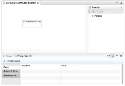
In conclusion, what you obtain from the example I showed, is the most basic graphical designer that it is possible to build with GMF and it is illustrated in the figure 3.8. It represents the definition of an instance of the class Person.
3.4. Graphical Modeling Framework (GMF)
Figure 3.8: Basic graphical designer
3.4.5 How I used GMF
As it is easy to understand, The Graphical Modeling Framework helped me to develop a graphical designer that is able to describe the environment and the incident hypotheses with diagrams providing the user an easy-to-understand interface and a large range of definition possibilities. The graphical designer, being an Eclipse extension too, is easy to extend with other functionalities. In this case, as GMF stores the created diagrams also in XMI, it was easy to create a new plugin that parses the XMI files into Event-Calculus, providing finally a correct environment and hypotheses definition to the tool kEEPER.
Chapter 4
Technical Solution
In this chapter I go down to the details of my software. In particular, I describe the meta-model built within EMF and the plugins generated by GMF with the manual changes I was obliged to make. At the end I describe the encoding Eclipse plugin which has the important job of parsing the instances of the meta-model into Event-Calculus.
4.1
The Meta-Model
The meta-model is at the basis of everything concerning this software and it needs to be strong enough to provide a fully customisable graphical designer with GMF.
4. Technical Solution
Figure 4.1: kEEPER Meta-Model
The EMF Model Plugin contains all the Java classes of the meta-model and it is composed by three packages: one for all the Java interfaces, a second one for all the implementation classes and a last one that handles the adapters for the entities in the second package. When an object needs to reference a list of other objects of the meta-model, EMF provides a data structure called EList which functionalities are similar to the common Java ArrayList.
4.1.1 Type and Instance
The first component of the meta-model surely is the Type-Instance relationship. Both instance and type have a “name” attribute that needs to be set by the final user.
Figure 4.2 shows how Type and Instance classes are related, in fact each instance can have only one type reference. For example, common names for type and instance could be “loc” and “r01” respectively that stand for “location” and the name of a room. The Type class is extended by two different kind of Type classes: Agent and Observer. It is important to have this split here to manage better the parameters of
4.1. The Meta-Model
the events later.
The Agent is a kind of type that normally performs an action while an Observer type is somehow watching the action being performed.
Figure 4.2: Type and Instance Class Diagram
4.1.2 Context Relation
As for the Type and Instance classes, the Context Relation class has its Java interface and its implementation class (see figure 4.3). In this case the attributes in the meta-model that need also to be defined by the user are:
• Name: a unique name that identifies the context relation in the diagram.
• InitialComplexEvent: the event responsible of the activation of the context relation.
• EndingComplexEvent: the event responsible of the deactivation of the con-text relation.
• Types: an EList of the types that represent the parameters of the context relation.
4. Technical Solution
Figure 4.3: Context Relation Class Diagram
4.1.3 Event
As described before, the events can be Primitive or Complex. Primitive events are low-level actions like system calls, while complex events are human actions that originate one or more primitive events. Each event (both primitive and complex) needs some parameters specified by types, like the ones of a context relation. These parameters, in the case of events, are classified into three different categories:
• Agent: the agent is who/what performs the action specified by the event. • Observer: the observer is what/who observes the action (camera, NFC reader,
etc...) and it can be a parameter of only primitive events.
• General Type: all other parameters that have a role in the performance of the action.
Technically, Primitive and Complex Event are two different classes that extend the more general abstract class Event. The abstract class contains an EList of Gen-eral Type storing the parameters of an event (Primitive or Complex), the Primitive Event class contains a reference to the agent and the observer parameters, while the Complex Event class contains a reference only to the agent parameter.
Furthermore, since each Complex Event class needs at least a Composite Defin-ition that describes its behaviour along the time, there is another EList inside the
4.1. The Meta-Model
Complex Event class that stores all the Composite Definition objects (from now on called Behavioural Description objects).
Figure 4.4: Event Class Diagram
4.1.4 Behavioural Description and Hypothesis
Behavioral Description and Hypothesis classes have the same structures because they need the same attributes and references even though they have a different semantic as explained in chapter 2.
Both have a name attribute that, for the Behavioural Description class, it needs to be the same as the name of the complex event is describing and, for the Hypothesis, it is a string composed by the letter “h” and a progressive number indicating the i-th hypothesis. For instance: h1, h2, and so on.
Furthermore, they both contain three EList structures to store the three different lists of predicates Happens, Holds At and Holds At Between objects.
The attribute timeInstants specifies the time window along which the predicate happens/holds before the complex event.
The remaining attributes help specifying the user if he/she wants to, program-matically create other behavioural descriptions with the same list of predicates but with all the possible time combinations. For instance if there are two predicates that happen/hold at two different time instants T1 and T2, then there are two different
4. Technical Solution
possible combinations and the algorithm would create two behavioural descriptions: the first one with the first predicate happening/holding at the time instant T1 and the second predicate happening/holding at the time instant T2, then the second behavioural description with the same time instants but swapped.
In particular the semantic for each of the three remaining attributes is the fol-lowing:
• any: it is a boolean and it activates the algorithm for the creation of all possible behavioural descriptions.
• firstTimeInstant: it specifies the starting time instant the “any” algorithm has to consider to create all the possible combinations.
• secondTimeInstant: it specifies the ending time instant the “any” algorithm has to consider to create all the possible combinations.
Figures 5a and 5b illustrate the Class Diagram for Behavioural Description and Hypothesis classes.
(a) Behavioural Description Class
Diagram (b) Hypothesis Class Diagram
Figure 4.5: Behavioural Description and Hypothesis Class Diagram
4.1.5 Predicates
The predicates Happens, Holds At, Holds At Between have a correspondent EClass and, consequently a Java Class.
4.1. The Meta-Model
To describe the predicates it is necessary that I first introduce how the dynamic parameters work. The dynamic parameters are those ones that are instantiated within a predicate and they are linked to a specific Type class object. It is important to remark here that when an event/context relation is defined, it is associated with specific types that constitute its parameters. In the events, these parameters can be of type agent, observer and general type but in the case of context relations, these parameters can only be of a general type. When a predicate is created, it is necessary to instantiate the dynamic parameters (of the event/context relation) that are linked to a type (agent, observer or general) in order to allow the definition of different instances of parameters of the same type for an event/context relation.
This is the Event-Calculus representation of a Behavioural Description object that explains better what I mean:
h a p p e n s ( l o g i n ( E , C ) , T , TR ): -t r a c e ( TR ) , emp ( E ) , comp ( C ) , loc ( L ) , emp ( E2 ) , time ( T ) , h a p p e n s ( s y s _ L o g i n ( E , C ) , T , TR ) , h o l d s A t ( in ( E2 , L ) , T , TR ) , h o l d s A t ( i s L o c a t e d I n ( C , L ) , T , TR ) , h o l d s A t ( h a s P e r m i s s i o n ( E , C ) , T , TR ).
What I want to point out from this example is that the user needs to have the possibility to choose an already used parameter (in another predicate’s event/context relation) for the predicate is defining or to define a new one. This is the case of the two first predicates linked to the event “sys_Login” and to the context relation “in”: they use two different parameters of the same type Employee: E, E2. That is the reason why I use the concept of dynamic parameters which classes are instantiated at the moment of the creation of a predicate.
4. Technical Solution
The figure 4.6 illustrates the Class Diagram of the predicates and the dynamic parameters.
Figure 4.6: Predicates Class Diagram
All the predicates have an EList called “parameters” that store all the dynamic parameters, then there is a reference to the Event/Context Relation object and one/two integers to specify the time instant or time interval when the predicate is true. For the “Holds At” and “Holds At Between” predicates there is also a boolean attribute that specifies whether the predicate is holding at that time instant/interval. Concerning the Parameter class (dynamic parameter), it is extended by the three different kind already discussed and it has a reference to the type Agent/Ob-server/General. Each dynamic parameter has also a name and an integer indicating the relative position in the event/context relation. For instance in the event “is-LocatedIn(C,L)” the parameter C has position 1 and the parameter L has position 2.
4.2. The Graphical Designer
4.1.6 Initially
Another part of the meta-model regards the Initially class. It has two attributes:
• contextRelation: it stores the Context Relation object that needs to be true at the initial state.
• instances: it is an EList of instances that are considered as parameters of the context relation.
Figure 4.7 illustrates the Initially Class Diagram.
Figure 4.7: Initially Class Diagram
4.2
The Graphical Designer
The graphical designer of the entire software is essentially composed by 6 Eclipse extensions, all of them structured as described in paragraph 3.4.4.
This division into 6 extensions comes from the need of the creation of different diagrams for describing the entire environment. Each graphical designer (extension) models the definition of a diagram that describes only a part of the environment. The division that I propose is the following:
• *.typeInstance.diagram: graphical designer for the definition of types and instances.
• *.contextRelation.diagram: graphical designer for the definition of context relations.
4. Technical Solution
• *.event.diagram: graphical designer for the definition of events.
• *.behavDesc.diagram: graphical designer for the definition of behavioural descriptions and its predicates.
• *.hypothesis.diagram: graphical designer for the definition of the incident hypotheses and its predicates.
• *.initial.diagram: graphical designer for the definition of the initial states.
Each of them collaborates to the total description of the environment. The final user, in order to describe the whole environment needs to create six different diagrams and thanks to GMF, it is possible to use elements in a diagram that were defined previously in another one. This can be the case in the definition of an event when it is mandatory defining some parameters that need to be associated to a Type object that has been defined previously in the Type-Instance diagram.
All the diagrams come with a workspace made up of the diagram area, a palette area and a property setting area at the bottom.
The final user should also start creating the diagrams in the same order I listed the GMF extensions above because the definition of each diagram requires some knowledge that only a diagram up on the list can provide.
GMF, as well as EMF, is a command-stack based platform that organises in a FIFO policy queue all the creation/editing/elimination operations of elements in-side the diagram. Thanks to the stack it is possible to handle various situations such as undo and redo operations. GMF uses the abstract class of GEF library “org.eclipse.gef.commands.Command”.
Several times, I adopted a programmatically creation of nodes into the diagram to facilitate the user experience avoiding a manual operation. To do so, it was important understanding how the Command class works within GEF and the result is the method shown below.
4.2. The Graphical Designer
Listing 4.1: Command for the creation of a node
1 public Command createAndExecuteShapeRequestCommand ( IElementType type , E d i t P a r t p a r e n t ) {
2 C r e a t e V i e w R e q u e s t a c t i o n R e q u e s t = C r e a t e V i e w R e q u e s t F a c t o r y . g e t C r e a t e S h a p e R e q u e s t ( type ,
3 P r e f e r e n c e s H i n t .USE_DEFAULTS) ;
4 o r g . e c l i p s e . g e f . commands . Command command = p a r e n t . getCommand ( a c t i o n R e q u e s t ) ;
5 command . e x e c u t e ( ) ; 6 return command ; 7 }
The method takes as input an EditPart object and the element type that refers to an entity of the meta-model. It then creates a request (2) that is then used to create a command (4) before the execution (5).
Now I describe all the listed above graphical designer GMF extensions in detail, one for each paragraph.
4.2.1 Type and Instance GMF extension
The first graphical designer is kind of basic and it represents Type and Instance objects in a concise way. From the right it is possible to drag-and-drop all the elements to the diagram: Agent Type, Observer Type, General Type and Instance. The picture 4.8 illustrates the case of three computers (m1, m2, m3) linked to their correspondent type «comp» and an employee which name is Alice.
4. Technical Solution
4.2.2 Context Relation GMF extension
The second diagram to be defined is the one related to the Context Relation. Each of them is represented as a unique node with the name attribute and the list of types (parameters of the C.R.) shown. The only element to be dragged-and-dropped from the palette is the Context Relation one and the attributes are modifiable from the Property area after having loaded the resources of the Type-Instance diagram.
As I said before, most of the diagram in order to be created, they need to load the elements from other diagrams. In this case the XMI file belonging to the Type-Instance diagram need to be loaded because each Context Relation object needs a list of parameters that are Type objects. It is possible to accomplish it within an EMF feature that is activated from the context menu by right clicking on the diagram. The example in figure 4.9 shows two nodes representing the two Context Relation objects: “in”, “hasBadge”.
Figure 4.9: Context relation Diagram and Palette area
In the property area (figure 4.10) it is necessary to set a name, a list of parameters and the activating/deactivating Complex Event object which determines when the context relation is true. It is clear that it is possible to select the initial and ending complex event only after having crated the events in the appropriate diagram.
4.2. The Graphical Designer
Figure 4.10: Context Relation Property area
4.2.3 Event GMF extension
The events use more complex graphical elements. There is a central node for the definition of a Primitive Event object or a Complex Event object and a link between an event node to each of its parameters.
Each parameter, that can be of type Agent, Observer or General has its own graphical representation as the sub-figures 4.11 show.
(a) Primitive Event Node (b) Complex Event Node (c) Agent parameter Node (d) Observer parameter Node (e) General Type para-meter Node
Figure 4.11: Event Graphical Elements
The standard way to instantiate Event objects expects the user to choose first the Primitive Event or Complex Event node and then to drag-and-drop the parameters from the palette and load the Type-Instance external resource by right-clicking again on the diagram. Then the third step is to link the event node to its parameter nodes and once it is done, the last thing to set is the Type object for each parameter in the