POLITECNICO DI MILANO
Master of Science in Computer Science and Engineering
A Flexible Framework for Configuring
Smart Interactive Experiences
Supervisor: Matera Maristella
M.Sc. Thesis by:
Filaferro Giovanni, matriculation number 898594
Gennaioli Michele, matriculation number 899062
Abstract
In a time where the technology is an important part of our lives, Internet of Things (IoT) devices are very widespread, but their programming is strictly related to the knowledge of specific programming languages that vary ac-cording to the device technology. However, nowadays, in several domains the need arises of defining Smart Interactive Experiences arises, i.e., usage situations created by orchestrating the behavior of multiple IoT devices, in order to tailor the behavior of general resources embedded in the environ-ment to specific situations that might better satisfy the needs of the final users. To facilitate the smart prototyping of Smart Interactive Experiences, this Thesis proposes a framework that consists of i) a middleware expos-ing primitives for the events and actions offered by an ecosystem of smart devices, and ii) a visual tool that can generate specifications of rules and process flows that can be translated and executed by different engines. The visual environment exploits a graph-based metaphor to let the user express sequences of actions that are then translated into a specification executable by a process engine: the nodes represent individual actions (both in terms of “sensing capabilities” and of “operation actuation”) that a smart device can perform and are designed with a high level of abstraction so as to make them intuitive to the final user. Thus, the contributions of this thesis are:
• A domain-specific language for expressing through high-level abstrac-tions the behaviour of smart objects;
• A design environment that allows the users to use in a visual manner the high-level abstractions to define flows of action activation on the connected devices. This environment offers a user-friendly interface for those not familiar with programming languages. It also provides rapid means to design and deploy a Smart Interactive Experience, even for those users who have an expertise in IoT programming.
• Runtime configuration of different devices without the need to deploy manually the new configurations.
The thesis also discusses:
• Some performance aspects related to the use of a specific, custom exe-cution engine in comparison with a well known framework, Node-RED, that today is largely adopted for the management of IoT devices; • The usability of the visual tool, by illustrating the results of a user
Sommario
In un’epoca in cui la tecnologia `e parte integrante della nostra vita, i
dis-positivi dell’Intenet of Things (IoT) sono molto diffusi, ma la loro
program-mazione `e strettamente legata alle conoscenze di specifici linguaggi di
pro-grammazione che possono variare a seconda delle caratteristiche tecnologiche del dispositivo. Oggigiorno, in diversi campi, cresce il bisogno di progettare
Smart Interactive Experience, cio`e situazioni d’uso create orchestrando il
comportamento di molteplici dispositivi, al fine di adattare il comporta-mento di risorse generali incorporate nell’ambiente a specifiche situazioni che possono soddisfare meglio i bisogni dell’utente. Al fine di facilitare la programmazione di Smart Interactive Experiences, in questa Tesi abbiamo sviluppato un framework che consiste di i) un middleware, che espone prim-itive per eventi e azioni offerte da un ecosistema di dispositivi IoT, e ii)
un tool visuale che pu`o generare specifiche di regole e flussi di processi che
possono essere tradotti ed eseguiti da differenti. L’ambiente visuale sfrutta una metaforea basata su grafi per permettere all’utente di creare sequenze di azioni che sono poi tradotte in una specifica eseguibile dall’engine. Quindi, i contributi di questa tesi sono:
• Un domain-specific language per esprimere, attraverso astrazioni di alto livello, il comportamento di dispositivi IoT.
• Un ambiente di definizione delle Smart Interactive Experiences, che permette all’utente di usare in modo visuale le astrazioni di alto livello per definire flussi di azioni nei dispositivi connessi. Questo ambiente offre un’interfaccia facile da usare per gli utenti con poca conoscenza sui linguaggi di programmazione. Anche per gli utenti che hanno nozioni della programmazione IoT, l’ambiente offre un modo rapido per definire Smart Interactive Experiences.
al singolo dispositivo manualmente. La Tesi inoltre discute di:
• Alcuni aspetti di performance, legati all’uso di uno specifico e person-alizzato engine rispetto a un framework comunemente adottato come Node-RED, attualmente molto utilizzato per la gestione di dispositivi IoT;
• Alcuni aspetti dell’usabilit`a del tool visuale per la programmazione dei
Ringraziamenti
Filaferro Giovanni
Ringrazio in primis mia Mamma Claudia e mio Papa’ Enzo per avermi dato questa possibilita’, esserci sempre stati e per aver creduto in me fin dall’inizio di quest’avventura. Vi ringrazio per avermi insegnato i valori piu importanti come onesta’ e cortesia. Vi ringrazio anche per avermi insegnato che con intraprendenza, tenacia, passione e perseveranza si possono raggiungere obi-ettivi inimmaginabili o molto difficili.
Ringrazio anche mio fratello Francesco, mia zia Laura, mio zio Enrico e mio nonno Sergio per l’affetto che mi avete sempre dimostrato e per essermi sempre stati accanto in questo periodo.
Un ringraziamento speciale va poi ad Erica, per aver avuto cura di me durante questi 5 anni sia nei momenti felici, sia in quelli un po piu cupi, scegliendo sempre di affrontarli assieme.
Ringrazio di cuore i miei amici per i divertimenti e le difficolta’ che ab-biamo condiviso in questi anni. Un ringraziamento particolare va a Michele, Nicola e Filippo: Michele e’ mio amico e collaboratore in questa tesi; Nicola e’ stato il mio compagno e amico speciale durante le avventure negli Stati Uniti; Filippo e’ stato il mio amico e coinquilino con cui ho iniziato quest’avventura. Infine, un grosso ringraziamento va alla professoressa Maristella Matera, relatrice di questa tesi, per il tempo e la fiducia che ha riposto in me in questi mesi per lo sviluppo di questo progetto.
Gennaioli Michele
Ringrazio mia madre Debora, mio padre Romano e mio zio Bruno per tutto il loro sostegno e per aver creduto in me sino alla fine. Grazie per avermi in-segnato che con la passione, tenacia ed impegno si puo’ raggiungere qualsiasi obbiettivo. Ringrazio anche i miei parenti per l’affetto dimostrato.
Ringrazio i miei amici, che mi hanno sostenuto e con i quali ho condiviso i momenti piu’ importanti di questa avventura, in particolare ringrazio Pietro e Giovanni, Pietro e’ mio amico e coinquilino che in questi 5 anni mi ha sopportato e supportato nei momenti migliori e in quelli peggiori, Giovanni e’ mio amico e collaboratore nella stesura di questa tesi.
Infine ringrazio la mia relatrice, la professoressa Matera che mi ha guidato, incoraggiato e aiutato in questi ultimi momenti qui al Politecnico.
Contents
Abstract I
Sommario III
Acknowledgements VII
1 Introduction 1
1.1 Scenario and Problem Statement . . . 2
1.2 Methodology . . . 3
1.3 Contributions . . . 4
1.4 Structure of Thesis . . . 5
2 State of the Art 7 2.1 IoT devices . . . 7
2.1.1 Evolution of IoT devices . . . 8
2.1.2 Characteristics of IoT devices . . . 9
2.2 How to program IoT devices . . . 10
2.3 End-User Development . . . 11 2.4 Task-Automation Tools . . . 12 2.4.1 Node-RED . . . 12 2.4.2 Prosa-UML . . . 15 2.4.3 Crosser . . . 16 2.5 Result . . . 16
3 Configuring Smart Interactive Experiences: Goals and Re-quirements 19 3.1 Use Case: GAIA . . . 19
3.2 Configuration and Synchronization of Multiple Devices . . . . 22
3.3.1 Physical Device capabilities . . . 23
3.3.2 Device Features Modularity . . . 23
3.3.2.1 Device Connection Module . . . 23
3.3.3 Device Service Layer Design Decision . . . 24
3.3.4 Visual Tool Design Decision . . . 25
3.3.5 Execution on Other Engines . . . 26
4 System Design 27 4.1 Device Service Layer . . . 28
4.1.1 Custom Engine . . . 28
4.1.1.1 Modules . . . 29
4.1.1.2 Scheduler . . . 30
4.1.1.3 Configuration Synchronizer . . . 31
4.1.2 Visual Tool: Front-End . . . 31
4.1.2.1 UI / UX . . . 32
4.1.2.2 Document Browser . . . 33
4.1.2.3 Picker View . . . 34
4.1.2.4 Canvas . . . 35
4.1.2.5 Scene Settings . . . 37
4.1.2.6 Scene Builder View . . . 39
4.1.3 Visual Tool: Back-End . . . 40
4.1.3.1 Module Handler . . . 40
4.1.3.2 Engine Syntax Mapper and Builder . . . 41
4.1.3.3 Debug Manager . . . 42
4.1.3.4 Device Synchronizer . . . 43
4.2 Technologies and Implementation . . . 43
4.2.1 Custom Engine . . . 44 4.2.1.1 Engine Components . . . 45 4.2.1.2 Modules . . . 46 4.2.2 Configuration Synchronizer . . . 48 4.2.3 Visual Tool . . . 49 5 Evaluation 51 5.1 User-Based Evaluation . . . 51 5.1.1 Tasks . . . 53 5.1.2 Data Collection . . . 54 5.1.3 Quantitative Evaluation . . . 54
5.1.3.1 Effectiveness . . . 55 5.1.3.2 Efficiency . . . 55 5.1.4 Qualitative Evaluation . . . 57 5.1.4.1 End-User opinion . . . 58 5.1.5 Discussion . . . 59 5.2 Technical Evaluation . . . 59
6 Conclusion and Future Work 61 6.1 Summary and Lessons Learned . . . 61
6.2 Outputs and Contributions . . . 62
6.3 Limitations . . . 63
6.4 Future Work . . . 64
6.5 Publications . . . 65
References 67 A User Study Questionnaires 71 A.1 Demographic Questionnaire . . . 71
A.2 Visual Tool Questionnaire . . . 72
A.2.1 Ease of Use . . . 72
A.2.2 Cognitive load . . . 74
A.2.3 General Questions . . . 75
B GAIA 77 B.1 Device . . . 77 B.2 Electrical Schemas . . . 82 B.2.1 Main Board . . . 82 B.2.2 Dots Board . . . 84 B.3 Configuration . . . 87 C Custom Engine 91 C.1 Configuration Sample . . . 91
Chapter 1
Introduction
Nowadays, in a technological landscape that is constantly evolving, Internet of Things (IoT) devices are very important for our daily routines[24]; IoT devices can foster important changes in our lives as they are increasingly pervading the environments we live in[7]. Also, in several domains the need of defining Smart Interactive Experiences arises, i.e., usage situations cre-ated by orchestrating the behavior of multiple IoT devices, in order to tailor the behavior of general resources embedded in the environment to specific situations that might better satisfy the needs of the final users [5].
If provided with tools to exploit the abundance of the related resources, end users could compose the different “behaviors” exposed by the surround-ing environment to accommodate their everyday needs. Programmsurround-ing the behavior of IoT devices is currently an opportunity for professional devel-opers only, as it requires the use of scripting languages that can also vary depending on the underlying hardware. IoT devices can also be programmed using different visual tools like Node-RED, Prosa-UML and Crosser, but they are thought for programmers and not for people without knowledge of programming.
This Thesis proposes an environment to easily and rapidly configure IoT devices without writing a line of code. It is adequate with respect to the expertise of non-technical end users, but it is also useful for those expert programmers who would need to rapidly deploy and test smart interactive experiences. The framework indeed is able to produce an output that can be deployed on multiple devices and executed by different engines and frame-works.
1.1
Scenario and Problem Statement
Let us consider a real case studio defined at Politecnico di Milano: during the month of January a group of student tested a new IoT device for kids with the collaboration of a primary school. The device, named GAIA [17], is an IoT device that interacts with kids through buttons, lights and sounds. The students created a very simple game to test GAIA: a child pushes the right button and a story is told. During the testing session the teachers were very interested in the IoT device, they would have liked to test it with several different games, both outside and inside the school, and they would have liked to do teach some lessons with this object.
The teachers’ ideas to use GAIA in different ways brought one big prob-lem: the impossibility to configure different games on GAIA without having some programming knowledge. We found two solutions to this problem: the first one was that one person with knowledge of programming languages would help them to write the code every time they want to try a new game. The other solution was that the teachers would use a visual tool to develop the game themselves and then run it on the device. The first one was not fea-sible, the other instead could be but the most known visual tools are thought for programmers, as they use specific terminology that is well known to soft-ware developers and not to other people. For example, Node-RED[14] is thought for people with a good knowledge of programming and it requires to install all the extra modules to work properly (for example loops are not included, so an extra library should be installed). Other tools, for example crosser [1], are thought for industrial work and data flow, thus are not ad-equate for the rapid prototyping of interactive experiences. It results that many times people can’t exploit at the most their devices’s features, and after some time they throw them away because they can’t use them as they want.
This Thesis aims to solve this problem by identifying High-Level abstrac-tions on top of low-level events and acabstrac-tions executable on IoT devices and defining a visual environment that, by offering a visual representation of the identified abstractions, can be used by everyone to rapidly configure a smart interactive experience. The visual tool generates a specification that can be directly executed on the different IoT devices; thus, if a teacher decides to hold a lesson with GAIA, he/she can use the visual tool, create a flow of actions and then transfer and run it on the GAIA device without the need
of any programming knowledge; during the simulation of a game or a lesson the teacher can also check if there are some problems, thanks to a visual debug modality that represent graphically how action’s execution propagate through the defined flow, and in case highlight problems, thanks to a runtime debugging that is able to show the execution state of the different devices.
1.2
Methodology
In this thesis we approached the problem of offering to the end users and also developers a visual framework for the rapid prototyping of smart interactive experiences. We worked on this problem through the following sequence of activities:
• Iot device prototyping: in order to make the GAIA device run, we created a first custom engine that can be installed on the devices to manage their execution and also support their inter-communication by means of a shared network;
• Analysis of case studies: thanks to the prototype of the execution en-gine, we were able to conduct a user study to assess the effectiveness and usability of GAIA with kids and teachers; the study helped us identify the relevant requirements to guide the successive steps of our work;
• Definition of a domain-specific language: we identified a set of primi-tives, which provide high-level abstractions representing low-level events and actions to be captured and executed by each single device.
• Design of a visual environment: we designed a user-friendly visual in-terface that can run on computers, tablets or phones. It is based on a visual metaphor that allow users to define flows of operations deter-mining the behaviour of single devices and the orchestration of multi-ple devices within commulti-plex smart interactive experiences. The visual metaphor provides a mean to represent the primitives of the domain-specific language previously defined.
• Evaluation: we performed a technical evaluation by comparing the per-formance of executing the processes defined with the visual tool with
both our custom engine and with Node-RED engine. We also con-ducted a user study as a preliminary evaluation of the visual tool with a group of students of Politecnico di Milano with a moderate experience in IoT programming.
1.3
Contributions
The thesis proposes a visual environment that works as a layer to create configuration files that can be run on other devices or visual tools, while doing runtime debugging of the flow created by that file (this function only works with our custom engine).
We introduced new primitives that are working at an intermediate level to make the configuration of the device easier. This level can be extended by the user if new functionalities would be needed to exploit new features of a device. These primitives follow a defined structure to facilitate their un-derlying implementation and to make them compatible with both the device and the visual environment.
We tested the introduced primitives on the GAIA [17] device. In this prototyping version, we are focusing on GAIA [17] features and components, such as light up a group of led or play an audio through the speaker. However, thanks to the modularity of the framework, the primitives and the related execution engine can be easily adapted and extended to any IoT device and to any smart interactive experience.
Therefore, the main contributions of this thesis are:
• A new approach to visual coding that does not require programming knowledge;
• A visual environment that provides visual primitives to configure smart interactive experiences and that translates the visual configuration into interpretable language for the IoT devices;
• Real time debugging shown on the interface, so that it is possible to know where the control flow stops during the testing of IoT devices; • An engine optimized to connect multiple devices and to coordinate
• Real time synchronization so that it is possible to send all the config-urations directly on the device.
After analyzing some well-known visual tools, we discovered that no one can provide a real time debugging feature on multiple devices. At the same time, we demonstrate that the performances of our custom engine are better of an online generic engine.
1.4
Structure of Thesis
• Chapter 2: is an overview of the past and present state of IoT devices and visual tools and describes their main features. Also it explain the End User approach to programming language.
• Chapter 3: introduces the idea of Smart Interactive Experiences, re-quiring the configuration and synchronization of multiple devices, and defines the requirements and goals of the thesis.
• Chapter 4: is divided into two sections, the first one is used to describe the architecture of the visual tool and customized engine, the other one is used to define the used technologies and the implementation aspects. • Chapter 5: describes the evaluations that are done to test both the engine and the visual tool. It is divided in 2 parts: the first one is about the End User evaluation where we test the Visual Tool, the second one is about the performance of the customized engine.
• Chapter 6: describes the conclusion and future development of this thesis.
• Appendix
(i) It reports the questionnaires used for the evaluation (Appendix A).
(ii) It explains the structure of GAIA [17] devices, its component and how it was configured during the first user study (Appendix B). (iii) It describes a configuration for the new custom engine taken from
Chapter 2
State of the Art
This chapter is divided in five main sections, the first one is about the evolu-tion and analysis of IoT devices, the second will explain how to program IoT devices, the third one will talk about end user, the fourth section will explore the visual tools and task-automation tools that can be used to program the IoT devices and the last one will present our solution.
2.1
IoT devices
Technological advances we are confronting today are influencing society [28] [25] [20]. End users can now exploit powerful, pervasive devices that offer several features, especially connectivity and sensors, and host the execution of multiple applications that until a few years ago were totally out of the users’ reach. In addition, the Internet of Things (IoT) facilitates the creation of ecosystems of heterogeneous and distributed services that enable the access through the Internet to functionality and data provided by physical devices equipped with electronics, sensors and actuators, and embedded software -the so-called IoT devices [7]. Sensors are exploited to “feel” -the environment, while actuators are used to communicate with the it.
The openings offered by IoT can be amplified by means of new approaches [19] [13] [30] that, based on high-level abstractions and adequate interaction paradigms, involve directly non-technical users in configuring the behavior of their IoT devices. End users possess the domain knowledge required to build applications that can support their tasks. The new technology scenario increases the end users’ attitude towards the new devices and applications.
2.1.1
Evolution of IoT devices
The first IoT device was created in the 1982, it was a vending coke machine [11] at Carnegie Mellon University, this peculiar vending machine could send history log through the network to let the University staff know the condition and status of the objects inside the machine. This was possible thanks to some micro-switches that could sense how many bottles were left.
In the years between 1993 to 1997 several companies like Microsoft tried to produce one of the most important features of IoT devices: the possibility to connect different machines (not computers) to the same network and control them through a computer.
In the 2000, LG started the first internet refrigerator program [27]: a refrigerator that could be connected with the internet, used to watch TV and many other functionality, but during that period it was unsuccessful, because it was considered unnecessary and the price was too high.
In the 2005 the company Violet created Nabaztag: an IoT device with the shape of a white rabbit which can be connected to the internet and other rabbits through Wi-Fi. It was programmable to an extent, it was equipped with led and a speaker to play news headline, alarm clocks, etc,. This IoT device was also used to understand how elder people interacted with this new technology [22].
The IoT idea emerged in 2009 when Kevin Ashton and his team at MIT’s Auto ID Center[6] coined this term to describe a system where the Internet is connected to the physical world via ubiquitous sensors.
The technology innovations of the last 10 years (2009-2019) brought a great spread of IoT devices, nowadays they are a part of our daily routines[24] and they touched most of the aspects of our life. Also, the spread of IoT devices stimulates the development of new technologies[26]. Some examples of IoT devices are:
• Amazon Alexa: a smart home assistant that can be connected with the internet and other devices like computers or smart TVs
• Samsung Refrigerator: a refrigerator that can be connected to the in-ternet and can send pictures of its inside to phones or it can be used to order food from home
• Apple Watch: a watch that can be connected to other Apple devices and internet. It has the same functionality of a smartphone
• Smart helmets: cycling helmets that can do health statistic analysis, take pictures and connect with Bluetooth to other devices
Nowadays it is easy to create a personalized IoT device with the right knowledge[21], thanks to the availability of resources as physical components and online guides, but still this opportunity is limited only to expert developers.
2.1.2
Characteristics of IoT devices
According to the classification proposed in Designing for End-User Develop-ment in the Internet of Things [8], IoT devices can be classified as settled, if they are installed in a fixed position or mobile if their position can change as in the case of wearable devices; or as asynchronous or synchronous depend-ing on the modality for senddepend-ing and receivdepend-ing data; for either individual or collective use, if they communicate data only to the owner,
IoT devices are spread and used in many different domains [28] [25] [20], about 18.2 billion IoT devices were produced by the end of 2015. Cisco’s forecasting estimates that more than 50 billion IoT devices will be deployed
by 20201, so to define them as IoT devices they need to have several
charac-teristics that are cited in this subsection. The most important characteristics are:
• Connectivity: IoT devices are connected to the web or other devices. This connection is very important, for 2 reasons: the first one is the possibility to interact with them using other devices without the need of a direct interaction, the second one is the possibility of retrieving data from the IoT devices. This data can reflect their internal status, or its different interaction with the external world.
• Sensors/Actuators: This internal components are defining the inter-action with the outside world and they collect data of different types. Sensors are used to collect data for example buttons, photo-camera, mi-crophones, proximity sensors, etc. Actuators are used to deliver data and to answer to external interaction such as light and sound emitters, electric valves, motor servos, relays, etc.
1
http://newsroom.cisco.com/feature-content?type=webcontent&articleId= 1208342
• Data Processing: After external stimuli, the IoT device has to process data in order to give back a response to the outside world. This process can be used for either simple analysis as to check the pressure of a button, or complex analysis as to identify an object through a photo-camera.
• User Interface: This is how the system can interact with the user to deliver data in a usable way that the user can understand.
This four features are giving to the IoT devices great flexibility and capability of adapting to different environments and goals.
2.2
How to program IoT devices
IoT devices can be programmed using different programming languages, such
as Python, Java, Javascript, etc.2, and through several options. For example,
it is possible to program a device from scratch, and use directly the program-ming language on the device (we used this approach to create a customized engine and test its performance) or it can be exploited a visual tool and program the device by using it. Still, we can use a task automation tool.
The so called Task-Automation (TA) tools [10], are gaining momentum. They have become popular as they offer very easy and intuitive paradigms to synchronize the behavior of objects and applications [23]. Through Web editors, users can synchronize the behavior of IoT devices by either: a) graph-ically sketching the interaction among the objects, for example by means of graphs that represent how events and data parameters propagate among the different objects to achieve their synchronization, or b) defining event-condition-action (ECA) rules.
The possibility to program IoT devices through graphical environment led to an increase of visual tool development[15][29] because this tools can support non-technical users to configure IoT devices behavior. Many of them, however, consist of pre-packaged solutions, e.g., vendor and device-specific apps for remotely controlling single IoT devices that cannot be easily adapted to the requirements deriving from specific domains and contexts of use.
In the last years the programming of IoT devices is more focused on the end-user aspects, so many new tools are created using protocols and visual
2
representation that are user friendly but still are mainly oriented toward developers.
2.3
End-User Development
One important challenge is related to the definition of correct paradigms based on correct interfaces that let the end user customize their own IoT Devices to suit their needs. EUD fits well this problem of customizing systems based on user’s needs [18].
EUD, unlike usual methodologies for the design of interactive systems, provides tools for the end users to compose the applications they use or to create new ones.
Some works in the literature come up with design techniques based on EUD approach, that gives to non-technical users the ability to compose IoT Devices [3] [4].
IoT devices can be accessed as services, because they can be provided with a URI (Uniform Resource Identifier) that identifies them on the Internet and are published by taking advance of traditional service technologies that enable the possibility to capture events and run actions remotely on the IoT device. The problems of programming
IoT devices can be seen as a special case of Web service mashup. In the case of service mashups, the platforms implementing an event-driven, publish-subscribe approach, such as the one described in A mashup environ-ment for end user developenviron-ment [9], synchronize Web APIs, so that the events produced by a service start operations on other services. This paradigm suits very well the need of synchronizing the behavior of smart objects [16]. Very often tools that are used to program IoT devices that are exploiting an end user approach are oriented to developers, while there is a lack of approaches using notations for non-technical users.
2.4
Task-Automation Tools
Event-driven architectures have been studied since many years to address the design of active systems in different fields, from active databases, to workflow design and context-aware applications [12]. They can be used when it is needed to organize the components of a system depending on the result, detection and consumption of some events.
In this architectural pattern the design and management of Event-Condition-Action (ECA) rules has a fundamental role. These rules allow the specifi-cation of active behaviour by means of events indicating a signal triggering the invocation of the rule, a condition that can determine the activation of an action, and the action that consists in an operation acting on data or functions also exposed.
Recently, different Web tools have revisited the ECA rule paradigm to address the problem of Task Automation (TA). In particular, they support the definition of ECA rules to synchronize the behavior of IoT devices and services [10]. Many of these tools are designed for non-technical people and offer wizard procedures that guide users during the composition process. One of the most popular is IFTTT[31] (If This Then That), a free Web platform, but is computational power is very low and it can be used mostly for basic interactions. Another one is Zapier that enables the composition of both Web services and IoT devices. It proposes a wizard to specify one event and one action in a “basic rule”, which can be later extended with further events and actions [Inc. 2016b].
Any TA tool offers visual environments for the definition of ECA rules. Such visual tools are very useful for rapid prototyping, as they require defin-ing rules trough visual notations instead of writdefin-ing code. In the next sub-sections we describe three visual tools that we identified as pertinent with respect to the work done for our thesis.
2.4.1
Node-RED
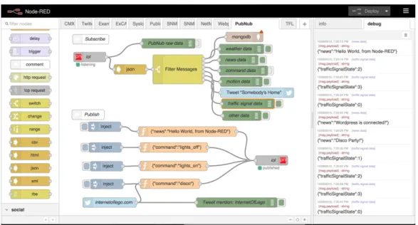
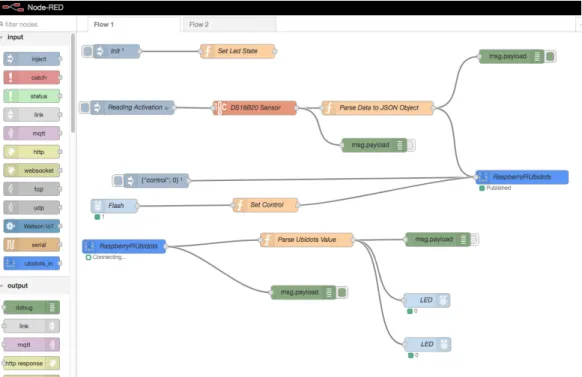
Node-RED [14] is a Open Source software used for programming IoT devices. It’s a visual tool that uses blocks as nodes. Each block is connected with others through arrows to create a flow of actions that is used to define the behavior of the some IoT devices.
by programmers to manage a specific feature of an IoT device. This feature confers to node-RED the capability of being adaptable to different needs and situations, so at the moment it is the most well-known visual tool and the one with the largest number of extension modules. In figures 2.1 and 2.2, we show the structure of a possible flow defined with node-RED and its components.
Figure 2.2: Node-RED UI Other Example
The characteristics of Node-RED are:
• Initialization: when installed Node-RED provides only for the basic functions, which don’t include programming constructs such as loops or selection blocks. So, the user has to manually install the related extensions from the command line.
• Extendable: it can be extended if the user needs something, but this brought to the problem that some modules are not compatible with others, thus wrappers are needed to make them interoperate.
• Master-Slave connection: the IoT devices are connected using a master-slave paradigm, according to which the master-slaves can only interact with a master and they cannot interact directly between themselves. This gives more stability to the sequence control flow but it overloads the requests and the work of the master node.
• No debugging: it is not possible to know at which step the control flow crashed or its blocked, because the visual tool does not offer the possibility to follow the execution flow of the IoT device.
• Device dependent configuration: each device has its own configuration panel so it won’t be possible to configure multiple Node-RED devices at once in one single interface.
• Use of JSON file: it produces JSON files with a defined structure, which make it easy to transfer flows between devices.
• Free visual tool
To work with Node-RED on an IoT device, it is needed to install its visual tool and its dependencies on the IoT device, then it can be run from another computer.
2.4.2
Prosa-UML
Prosa-UML [2] is an object-oriented visual tool used for programming IoT de-vices, and other functionalities, such as busyness planning, database system development.
It uses a visual interface based on the UML notation, so the flow of actions to be defined for synchronizing IoT devices can be represented through UML diagrams, runtime flowchart, etc. It is very easy to use if the user knows how UML works, otherwise it can be rather difficult to use because UML uses peculiar shapes and notations for its diagrams.
The characteristic of Prosa-UML are:
• It supports the translation of diagrams towards different programming languages.
• Device dependent configuration: as for Node-RED, but with the differ-ences that all of the devices can be reunited in the same project. The different devices needs to be programmed in different environments. • No debugging: it is not possible to debug the flow chart at runtime. • Industrial use: it is a tool used in industrial contexts, so it is optimized
for some defined operations.
2.4.3
Crosser
Crosser [1] is a visual tool used to deploy and retrieve data on IoT devices. Unlike the other two visual tools previously described, Crosser doesn’t directly program the IoT devices, while it sends them the data to make them work and retrieves the results.
It use a simple but limited interface: it’s composed by nodes with a brief description of what they can do, but this one is thought for programmers so it is difficult to understand without the appropriate knowledge.
The characteristic of Crosser are:
• It can process more data than Node-RED
• No Programming: it is a tool used to retrieve and send data, it does not support the deployment of code on IoT devices but it gives them the data to work with
• Runtime debugging: it use a runtime debugging
• One screen for more devices: it use the same screen to connect the devices and to send data to them
• This tool requires a paid license to be used
2.5
Result
We have created an IoT device named GAIA [17] and a customized engine. In section 2.4, we illustrated some visual tools. However, we realized that all of them solve only partially the problems that we identified when configuring the GAIA device.
Node-RED and Prosa-UML are both meant to create code to run on the device, but they cannot support run time debugging or they do not allow to program more devices on the same screen.
Instead, Crosser does the opposite, it supports runtime debugging and the programming of multiple devices on the same screen, but it doesn’t allow to create code to run them.
All the tools are using a visual block interface, but they are thought for programmers.
Our solution, which we will describe in the next chapters, uses a visual block interface with nodes that are easy to understand without programming knowledge. It enables the runtime debugging on our engine, and it allows programming multiple IoT devices on the same screen. Also, it can send code to the devices.
Moreover we have done a performance test between Node-RED and our engine, and we have found that the personalized engine has a better perfor-mance than the generic one.
Chapter 3
Configuring Smart Interactive
Experiences: Goals and
Requirements
3.1
Use Case: GAIA
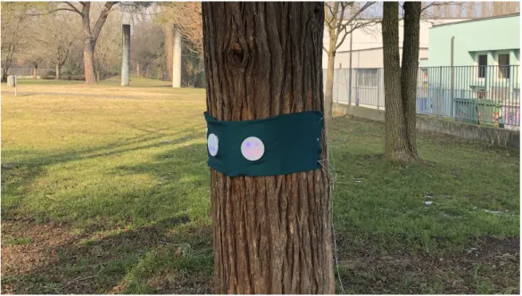
GAIA [17] is an interactive toy, which aims to stimulate kids in the first years of primary school (5/8 years old) to play outdoor and explore natural elements. The device is a tangible band equipped with 4 bright buttons and 2 speakers tied on a tree. The children interact with the device through lights, sounds and touch.
GAIA has provided the starting point for this Thesis, as its develop-ment has provided the fundadevelop-mental requiredevelop-ments for the design of the entire framework.
Figure 3.1: GAIA on a Tree
Figure 3.2: GAIA Single Dot
One peculiarity of GAIA is its ability to use a rather simple JSON config-uration file with a custom structure to define actions to be executed. There were pre-defined sets of actions that, if combined together, could create an
unlimited variety of games. Those actions can be further extended by cre-ating custom ones and then can be used in the action file to create new interactions.
An example of the GAIA language is the one below:
[ { " p a r s e I d e n t i f i e r ": " W A I T _ I N P U T " , " a t t r i b u t e s ": { " a v a i l a b l e _ d o t _ i n d e x e s ": [ 0 , 1 , 2 , 3 ] } } , { " p a r s e I d e n t i f i e r ": " P L A Y _ A U D I O " , " a t t r i b u t e s ": { " p a t h ": " c o n f i g / a s s e t s / a u d i o /1 _ 1 _ m o n o . wav " } } , { " p a r s e I d e n t i f i e r ": " S H O W _ C O L O R " , " a t t r i b u t e s ": { " f a d e ": true , " c o l o r ": { " red ": 255 , " g r e e n ": 255 , " b l u e ": 0 } } } ]
This file contains a series of actions that have an identifier (that will later be used by the correct action handler) and share some attributes. This has been the starting point for this thesis!
First, the abstraction technique used in GAIA has been enforced to ensure enhanced modularity. All the components have been moved to modules.
Device logging has been modularized and exported as part of the visual tool to provide Live Debugging.
now supports parallel tasks.
Also, the configuration JSON model has been redesigned to ensure effi-ciency and simplicity to manage alongside the Visual Tool.
In GAIA the main problem has been reusability of actions and action files. That’s what brought us to introduce the concept of scenes.
A detailed representation of GAIA and its internal structure is presented in Appendix B. Also it shows the board schematics used to physically develop the device.
3.2
Configuration and Synchronization of
Mul-tiple Devices
Let us introduce the main elements that characterize the Configuration of Smart Interactive Experiences. Imagine that a user would need to configure multiple devices which should behave in a synchronized manner communicate to trigger actions in a synchronized manner. If configuring devices through a visual tool, the user will be provided with a set of primitives (events and actions) to be combined together to create an operational flow.
This the starting point to develop a new higher concept called scene: A scene is defined as a group of events and actions and can be considered as a macro-operation that the system can execute with inputs (coming from other scenes or actions) and outputs (to other scenes or actions). A scene can be entered only in one entry point and exited only to one exit point, so it can be executed only if an action triggers it and when it finishes execution it triggers its next action in the chain.
Actions can be defined on each device depending on the features that it exposes. Each feature can be mapped onto modules able to handle the corresponding actions. More specifically, a module is a container of basic actions that can be used for configuring a particular device.
When configuring different smart interactive objects it is really important to test if the scenes combining their features behaves correctly. This is why Live Debugging makes the difference showing current states of actions and scenes directly in the visual tool.
These keywords, highlighted in bold above, are the concepts that will guide the definition of the objectives and the characterization of the field of action to develop our system.
3.3
Goals and Requirements
The goal of the system that is the object of this work is to offer a set of tools capable of simplifying the configuration process of Smart Interactive Experiences, enabling also people that are extraneous to programming to perform the configuration.
To achieve our objective, there are a number of requirements that must be fulfilled.
3.3.1
Physical Device capabilities
As a first requirement, the physical devices that should be used can be dif-ferent in features and capabilities. The only need they must fulfill is that they contain a processor capable of running parallel tasks efficiently.
Wi-Fi connectivity is not a must have, since some configurations might not require it, but, in order to configure the device wirelessly it becomes required.
In order to enable Live Debugging, Bluetooth is required!
3.3.2
Device Features Modularity
Since not all devices share the same features (one can have only LEDs, an-other only speakers) it can support only the modules built for that specific functionality.
In the case a module does not exist for a particular functionality it’s up to the developer to create a new one that should be compatible with at least one of the desired engines.
3.3.2.1 Device Connection Module
To enforce connectivity between multiple devices, a publish-subscribe proto-col has been used so that it becomes even simpler to abstract its mechanism into modules and actions that can be easily understood.
publish-subscribe is a messaging pattern where senders of messages, called publishers, do not program the messages to be sent directly to specific re-ceivers, called subscribers, but instead categorize published messages into classes without knowledge of which subscribers there may be.
This is a really simple concept that once encapsulated into a series of actions can be easily understood by a wide variety of users.
3.3.3
Device Service Layer Design Decision
From the first moment, the custom engine has been engineered and built from the ground up to leverage both the simplicity and modularity of Node-RED and the robustness of BPMN.
To provide modularity, we have created a bundle model to encapsulate all its core aspects.
To make it simple to configure, we have developed a custom file structure. Lastly, to provide robustness, some BPMN components have been ab-stracted and turned to Actions encapsulated in a “Base” module that is called “Core” and it will be available to all devices using this custom engine.
This will be seen later when talking about architecture.
Also, in order to ensure parallelism and sequentiality in operations inside the engine, the concept of Actions Worker has been introduced. A worker is a small part of the engine which handles all the action interactions and schedule in order to make them work always as expected limiting the amount of failures that can occur.
In order to make the system work properly, in the single device there has been built a layer which is called “Configuration Synchronizer” that enables the configuration mechanism for all the considered engines.
The main networking options to build this Synchronizer upon to, were:
Name Pros Cons
Bluetooth Simpler to adopt Slow transferring high
volume files such as audio tracks.
Wi-Fi SSH Easy to use via
terminal. Provides fast and reliable file transferring as well as bash script deployment
A little more difficult to embed in the Visual Tool since the Synchronizer has a counterpart there. Also, It requires the devices to be under the same network.
What it was chosen to do has been:
• Use Wi-Fi to build the Configuration Synchronizer to maintain stability when transferring big scenes (this would be the average case scenario) • Use Bluetooth inside one of the custom engine modules (the Debugging
module) to provide live debugging since it uses really small packets.
3.3.4
Visual Tool Design Decision
This Tool has been imagined from the first moment with the final user in mind. Therefore a simple but effective user interface was necessary to be developed.
The main platforms we could opt for were:
• Android: it supports a wide range of devices but many of them would not have enough performance to handle all the visual tool features or they would not provide the kind of user experience it was supposed to achieve.
• iOS (and macOS): it does not support all devices on earth but it provides strong graphic performance, bluetooth capabilities in all de-vices, easy file sharing and free iCloud synchronization to backup data without doing extra effort. Also with Project Catalyst released in June it is now possible to build the app from the iPad and turning it into a macOS app with a small effort.
From the perspective of creating the best experience for configuring smart interactive devices, the iOS environment has been chosen. The app will run on iPhones, iPads, iPod Touches and even on macOS thanks to “Project Catalyst”.
This choice ensures not only reliability and workspace synchronization between the iOS devices, but also performance and hardware capabilities such as Bluetooth to enable Live Debugging.
To provide extendability and flexibility a new component called “Module Handler” needs to be developed. It is used to load and provide to the user files that dictate how a module behaves on a device as well as some mapping rules to be supplied to another component called “Engine Syntax Mapper”
that transforms the intermediate visual language into configuration files to be used in all the considered engines.
The last component needed to enable the Live Debugging feature is the one called “Debug Manager” which is in charge of connecting to the de-vices and listens to their messages updating accordingly the User Interface to reflect the current actions on device.
3.3.5
Execution on Other Engines
In order to provide universal access to our framework, the visual tool language structure has been designed for easy translation of actions and scenes among different engines. An example of those can be both our Custom engine or also Node-Red.
Chapter 4
System Design
Now that the requirements and goals have been made explicit, it is important to define what are the steps that have to be taken when designing the system according to our methodology.
An overview of the overall components interaction architecture is shown in Figure 4.1.
Visual Tool
Engine Syntax Mapper Device Synchronizer Debug Manager Module Handler Device Node-RED Configuration Synchronizer Custom Engine
Figure 4.1: High Level Architecture
It is divided in three main layers: Device service layer, Visual Tool Front-End and Visual Tool Back-Front-End. The first one defines our Custom Engine, the last two layers relate to the Visual Tool.
4.1
Device Service Layer
The device layer is composed of some components that are independent one to the other and they interact directly with the engine. This ensures consistency also when a component is changed, so that it does not impact the others in the service layer.
It is important to Note that, the execution of scenes on the device can be handled by the custom engine that we designed, as well as by other engines that are able to manage the execution of the action flow. In our current prototype we tested the execution of scenes on Node-RED. However, assum-ing that a proper transformation layer is provided, the action flow defined through the visual editor could be executed on any other engine. In the following we will concentrate on the organization of our custom engine.
4.1.1
Custom Engine
In Figure 4.2 we report the main components of the custom engine:
The main part of the Custom Engine is the Scheduler, which is in charge of scheduling tasks and running all the scenes.
The other defining part of this engine is composed by modules designed to be easily plugged-and-played so that they can be removed and added without compromising the system capabilities.
Also, the scheduler function would be to load and manage these modules to validate and run all the actions defined in scenes.
Scenes are loaded into the engine thanks to a Scene Descriptor (one for each scene) which is a data structure that defines properties, options and action flows of a scene.
Core
Scheduler
Scene 1 Debug Scene 2 Networking … … … … CUSTOM ENGINE MODULES SCENE DESCRIPTORSFigure 4.2: Custom Engine Overall Architecture
4.1.1.1 Modules
They are composed by 4 parts: • actions
• dependencies • handler • configuration
Actions are all the actions the module exposes and they are the actual components that will be mapped from the scene descriptor. They will be directly managed by the custom engine core.
Dependencies is a descriptor of all the dependencies that actions will use. For example if they rely on 3rd party software, its definition should be inserted here.
Handler is an optional component that will be notified when the engine switches actions or changes state. It will be used to schedule tasks or modify its actions to provide more functionalities in a global context.
Configuration is a container in which configurations of the environment can be written. They will be available later to all the actions and their handlers (also the module global handler would get those options).
In Figure 4.2 there are represented the 3 main modules: Core, Debug and Networking which are the default ones that will always be available in all devices.
4.1.1.2 Scheduler
The structure of the Scheduler is represented in Figure 4.3.
CUSTOM ENGINE / MAIN
Action Worker
Base Action
Logger Global Container
Scene Loader
Figure 4.3: Custom Engine Internal High Level Architecture
This is the component which is in charge of scheduling tasks and run all the scenes. Also, it manages modules and loads their content and descrip-tors. It executes these functions thanks to the components described in the following.
Scene Loader It is the component in charge of loading, parsing and man-aging the scenes. When the engine starts, it looks for the scene definition and loads it in memory, then it validates all the actions contained in it and parses them. Also, when a scene requires to load another scene, it reruns the validation and parsing process for that new one.
Action Worker The action worker can be also pictured as the Heart of
the Custom Engine. Not only because it executes the scenes flows but also because it ensures parallelism, consistency and performance throughout the system.
It requires a scene flow to be ran and a mode. Mode can be of 2 types: • Sequential : All the actions in the supplied flow will run one after the
other.
• Parallel : All the actions in the supplied flow will run all at once. Action workers can also generate other action workers: this way scenes can be executed from the start to the end only by the means of a worker simplifying the scheduling process.
Global Container and Logger Global Container is a place in which
actions can add and retrieve content to be shared between each other. The logger is also available globally and logs all the system and custom data securely to trace action execution flow for debugging purposes.
4.1.1.3 Configuration Synchronizer
The configuration synchronizer job is to receive the new configurations and refresh accordingly the custom engine. Also, it should provide an interface to send and receive files, as well as an authentication layer to secure the files transfer and validate the connection.
4.1.2
Visual Tool: Front-End
We here describe the front-end of our visual environment, i.e., the user in-terface that the user exploits to configure visually the smart interactive ex-periences. We start with a usage scenario illustrating the UI funtions and the supported UX, and at each step we define how the user will interact
with the visual tool. We will then illustrate the components that enable this interaction.
4.1.2.1 UI / UX
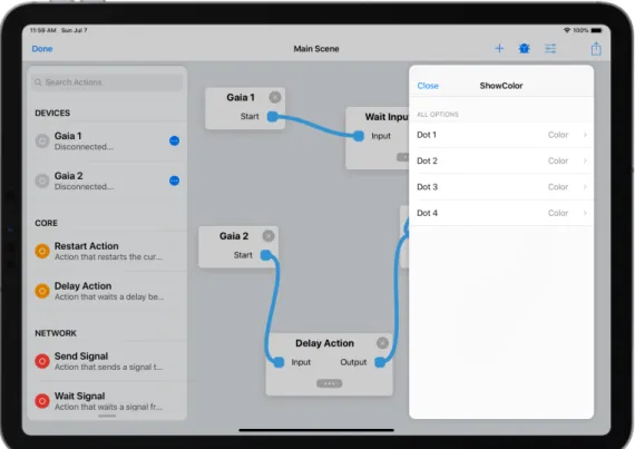
The teacher Veronica decided to use GAIA [17] to create a game for her students, so she decided to use our Visual Tool to create it. She starts the application, the first screen that she sees is document picker (shown in Figure 4.5) where she can either pick an existing document or create a new one. She decides to do the latter. The next screen that she sees is the Scene Editor, it is the core of all the visual configuration part (Figure 4.4).
Figure 4.4: Scene Editor
In this new view, she sees on the left a flexible picker view to easily drag and drop components inside the canvas: the devices to configure are added as component on the flexible picker and a search bar is provided to help her
search the right components, so all the items she needs are located on the same view and they are easy to find. Also she sees the Main Navigation Bar which contains buttons for live debugging, to open the Scene Setting, to export the created scene. She starts by adding her device, so she opens the Scene Setting, that will show her all the configured devices, then she clicks the button to add a new device and so she adds it. Now she returns to the Scene Editor and she starts by dragging out her device, then she uses the search bar to find the components she needs and in the end she deploys her new document into her device. Now Veronica can run her scene in the device and she can use her new game with her class.
4.1.2.2 Document Browser
When the visual tool starts, it presents a document picker view in which the user will be able to open a previously created document, move and manage it, as well as create a brand new one. This view is shown in Figure 4.5
Main Navigation Bar At the top of everything, there is a navigation bar which features:
• A back button, to go back to the document picker
• A share button that first asks the user if he / she wants to export the scene to the custom engine or converting it to Node-RED, then it prompts the user with a share sheet (Facebook, email, message, ...) to save or share the exported document.
• A debug button that is in charge of activating the debug session with Live Debugging for all devices that support it. Its functioning is pre-sented in Subsection 4.1.3.3.
• A settings button that when tapped it shows all the scene settings as presented in Paragraph 4.1.2.5.
• A button to open the Scene Builder View to create a custom scene.
4.1.2.3 Picker View
This Scene Editor features on the left a flexible picker view to easily drag and drop components inside the canvas. Devices becomes components on their own and are used as entry points for the configuration mechanism.
Also, subscenes to the currently visualized scene are shown in the picker view. These are treated as components too and can be dragged into the canvas to be used as actions.
There is also provided a search bar to simplify search between modules components. When an action is added to the canvas, a unique identifier will be generated for it that will later be used by the Debug Manager to identify it.
Device Section All devices that were previously configured accordingly
are detailed by their name and their status (Connected or Disconnected). There is also a button that opens a contextual menu which displays some options such as
• Device Reachability Check (checks if the device is nearby and reach-able)
• Synchronize Scene (Button that starts the scene synchronization pro-cess on that particular device)
Modules Section All actions and their relative modules are shown on a
list. Only the modules specified for the available devices will be shown. Actions are detailed on a single list item by their name and an informa-tional description to gather some information about them.
Scene Section If the user created a scene by combining multiple actions,
that particular scene is shown on a separate section on the picker and can be dragged onto the canvas as a normal action would.
It also will feature a contextual button to open the Scene Builder View for that particular scene.
This Scene Builder View will be further explored in Subparagraph 4.1.2.6.
4.1.2.4 Canvas
The main part of the Scene Editor is the Canvas, represented in Figure 4.4 as the full screen part that contains actions and their links.
Each action is represented as a block that has hooks to link one to the next.
By simply dragging those hooks, a link is created.
Also, if the action supports parameters, a button appears and by tapping on it the user is brought in a modal view (as shown in Figure 4.6) that has options for configuring such parameters.
Once tapped on one of the available options, its value can be adjusted and a view is presented like the one in Figure 4.7. This view’s content varies according to the option value type.
Figure 4.7: Action Option Detail (Color Option)
4.1.2.5 Scene Settings
In this modal view, there is shown a list of devices and a button to add a new one (Figure 4.8).
Each element can be tapped to edit its settings.
When creating or editing a device a new view is shown showing all the fields necessary for the device configuration as pictured in Figure 4.9
The required device parameters are: • name: the device name
• hostname (or ip address) • username (SSH username) • password (SSH password)
Password will be used only once and it is needed at first login on device to save the device’s SSH Key in it.
hostname, username and password are required only if the user wants to enable the custom engine synchronization.
Figure 4.9: All Devices
4.1.2.6 Scene Builder View
This particular view is really similar to the Scene Editor apart from the fact that in the navigation bar there are only three buttons: one to close the view, one for saving the scene, one for creating another scene in the scene. When the save button is tapped, if it was freshly created, the system asks for a name to label the scene, otherwise it saves it in the scenes section of the Scene Editor.
Also, there is no device options from the picker panel because an embed-ded scene is supposed to become a component to be used across multiple devices.
Another important aspect of the Scene Builder View is that there are always two persistent actions in the canvas that can’t be removed. Those are the entry and exit points of the scene. Much like a BPMN subprocess look.
4.1.3
Visual Tool: Back-End
This subsection is used to describe the components that the Visual Tool owns to work properly.
4.1.3.1 Module Handler
This is the component of the app that parses the module definition file and maps it in internal structures that will be used both by the Scene Editor (and Builder) and the Engine Syntax Mapper.
It is structured as a set of module descriptors each of them configured with the following information:
• name: the module name
• description: the module description • actions: a list of action descriptors
An action descriptor is comprised by the following information: • name: the action name
• description: the action description
• acceptedParameters: a dictionary containing all the available pa-rameters that can be configured for that particular action. They should be treated as a key-value pair where the value corresponds to the type that key belongs to: file, string, number, color, list [type] where “type” corresponds to one of the previously specified types and it’s a list of that particular type.
• mapping: it is a dictionary containing mappings for the engines. This will be further explored in Subsection 4.1.3.2.
An example of this structure can be the following (please note that it is shown as a JSON file but it can be in any language):
[ {
" n a m e ": " C o r e " ,
" d e s c r i p t i o n ": " C o r e M o d u l e c o n t a i n s all the n e c e s s a r y a c t i o n s " ,
" a c t i o n s ": [ { " n a m e ": " P l a y A u d i o T r a c k " , " d e s c r i p t i o n ": " P l a y s a s p e c i f i e d a u d i o t r a c k on the d e v i c e ." , " a c c e p t e d P a r a m e t e r s ": { " t r a c k ": " f i l e " } , " m a p p i n g ": { " c u s t o m E n g i n e ": { " p a r s e I d e n t i f i e r ": " P L A Y _ A U D I O " , " p a r a m e t e r s M a p ": { " t r a c k ": " p a t h " } } , " n o d e R e d ": { " t y p e ": " g a i a _ p l a y _ a u d i o " , " p a r a m e t e r s M a p ": { " t r a c k ": " f i l e _ n a m e " } } } } ] } ]
4.1.3.2 Engine Syntax Mapper and Builder
This component is the one in charge of building the scene and exporting it in all the requested formats (with all the included assets). In this thesis we covered our Custom Engine and Node-RED mappings but this can be applied to other engines by writing the mapper and mapping definitions accordingly. First, the Engine Syntax Mapper locates the descriptor (as described in Subsection 4.1.3.1) that contains all the mapping information for actions and modules.
Secondly it iterates through all the actions and links in the scene using that mapping descriptor to translate them in the requested engine type.
The mapper is an abstract component that should be overridden each time a new mapper should become necessary. In figure 4.10 there is a clear high level example on how it looks like.
Node-RED Mapper Custom Engine Mapper
Mapper
Figure 4.10: Mapper Architecture
The key element of this component is a mapping function that takes as parameters the scene description (which contains all the embedded scenes, actions and links) and also the available modules list prepared accordingly by the Module Handler and outputs the built files and assets.
Needless to say, each mapper should behave differently while proceeding with the mapping process in that function’s context.
4.1.3.3 Debug Manager
This is the component that is in charge of connecting to the devices and listen for notifications.
It will listen for messages coming from each device and request the UI to show them on screen.
Once the connection is established, packets will be received when an ac-tion is triggered on device. The message received By the Debug Manager contains the unique identifier of that action and also the timestamp in which it was triggered.
The scene editor will be immediately notified and the UI should update accordingly to show the change on screen.
When the scene is edited and it becomes out of sync, the Debug Manager will be automatically disabled until the new actions and scenes are uploaded
to the device.
4.1.3.4 Device Synchronizer
This particular component is the one that gathers all the scene data, makes a mapping request to the Syntax Mapper and Builder for each device and in-stantiates a connection with it thanks to the credentials that were previously specified.
It first triggers the cleanup process on device which stops all previously running processes.
Then it uploads the files and triggers one of the on device processes to enable the current uploaded scene. This particular operation is called the deploy routine and its job is to start the new processes with the updated scenes.
In the end it notifies the UI to prompt the user that the synchronization was successful or not if some errors occurred.
4.2
Technologies and Implementation
This Section describes our current prototype, in terms of the adopted tech-nologies and related implementation decisions. We will also discuss about some tools that helped us during the development of the system.
In this thesis we have focused on leveraging the power of a Raspberry PI Zero W that offered all the capabilities and the largest variety of customiza-tion rather than an Arduino or similar devices.
Visual Tool
Engine Syntax Mapper Device Synchronizer Debug Manager Module Handler Device Node-RED Configuration Synchronizer Custom Engine
4.2.1
Custom Engine
Since it was chosen for simplicity to build the entire system upon a UNIX-like system, the custom engine was completely built using Python (version 3.7). For the custom engine, as said earlier, we opted for implementing it in Python since it is fast, flexible and can be run without any kind of issues in an UNIX like environment.
The other option would have been to use Javascript (using Node.js frame-works) which could have given us all the same benefits as Python does but the last one is more efficient and suitable for Object Oriented Programming. For uploading and deploying actions and scenes, Bash scripts have been developed thanks to their ease to be ran in an SSH session that can be triggered remotely.
All our implementations have been targeted to a Raspberry Pi Zero W that has been the most suitable choice thanks to its flexibility and extend-ability. Also its size has been really a determinant factor on the choice we made.
To create action scenes we analyzed both JSON and YAML. Their com-parison is shown in Table 4.1.
Name Pros Cons
JSON Built-in libraries
are present in almost all programming languages
A JSON file can become really large, especially when lots of nested objects are present.
YAML Smaller files:
nesting is provided with a tab indent
Usually requires an external library to be parsed.
Table 4.1: Scene Language Options
Needless to say we chose JSON file format which is the most used and also we didn’t want to rely on 3rd-party libraries that won’t always be maintained. The only external library that has been used to build the core of the Custom Engine has been asyncio which simplified a lot the multithreaded part of the ActionWorkers. This library is one of the most used in python projects thanks its simplicity and completeness. That’s why it was chosen
to leverage its power and use it in the main part of the Custom Engine. In Appendix C we describe a configuration file used for GAIA [17] device.
Since modules can have dependencies, all of them can be specified in an installation script placed inside the module which installs all the requirements during the system setup.
4.2.1.1 Engine Components
In this subsection we illustrate the implementation of the engine components reported in Figure 4.2.
Scene Loader It is the component in charge of loading, parsing and
man-aging the scenes. When the engine starts, it will locate the folder at the root called scenes/active which contains all the active scenes. For each scene it locates a file called init.json which is the one that contains the starting point of a scene and parses it into a list of usable Actions.
Action Worker The Action Worker is a class which takes as input a scene
and a modality (which can be parallel or sequential) and runs all the actions contained in that scene.
If an action produces other actions, the Action Worker would add them to the chain. When the mode is set to parallel, the action worker generated another worker (with mode set to sequential) for each action and runs it.
Global Container and Logger Global Container is a Singleton which
acts as a variable container shared globally among all modules to be used in custom actions.
The logger is also available globally and logs all the system and custom data both to a terminal window but also on a saved file in order to understand what happens in case of failure.
Base Action The Base Action is the basic class in which all actions defined
in the other modules should inherit from. Its key point are:
• parseIdentifier is the identifier the class exposes to help the Scene Loader instanciate the correct class.
• When the action first loads the setup() method is called supplying all the parameters that were configured in the JSON file.
• When the action is about to start the prepare() method is called sup-plying all the parameters previous actions passed through.
• start() will be called when the action starts. • kill() will be called before destroying the action.
• complete() can be called during the action lifecycle and marks the ac-tion as complete to the worker.
• produceActions() creates a set of actions and adds them to the current queue of the worker.
4.2.1.2 Modules Module Name action_name.py … action_name.json Actions config.json install.sh (optional) Module_Name.py (optional)
CUSTOM ENGINE / MODULE
Figure 4.12: Custom Engine Internal Architecture
As It can be easily deduced from Figure 4.2, modules are completely detached from the main logic to make possible the feature-based architecture.