Analisi del trasporto del trizio nei sistemi SFR
Descritlori
Tipologia del documento: Collocazione contrattuale:
Rapporto Tecnico
Accordo di programma ENEA-MSE: tema di ricerca "Nuovo
nucleare da fissione"
Radioprotezione Prodotti di fissione
Tecnologia dei metalli liquidi
Generation IV Reactors Argomenti trattati:
Sommario
Uno degli isotopi radioattivi più difficili da contenere all'interno dei reattori SFR è il trizio in
quanto diffonde prontamente attraverso i materiali strutturali alle temperature operative e
conseguentemente può essere rilasciato in ambiente. AI fine di studiare ed analizzare possibili
accorgimenti necessari per ridurre l'entità dei rilasci di trizio in ambiente è stato sviluppato un
codice di calcolo in linguaggio MATLAB (SFR-TPC), il quale viene utilizzato per valutare i
rilasci ditrizio in ambiente e gli inventari di trizio all'interno dei reattori SFR.
L'analisi condotta con l'utilizzo del codice SFR-TPC su un reattore di tipologia "a vasca"
denominato PFBR (Prototype Fast Breeder Reactor), ha mostrato che, sotto alcuni ipotesi
conservtive, solo circa 1.6 mg/y di trizio (su 3.874 g/y prodotti nel core e rilasciati nel
refrigerante primario) raggiungono il ciclo del vapore e vengono conservativamente
considerati come rilasci in ambiente. Nonostante le ipotesi conservative assunte il dato di
rilascio ottenuto non costituisce un elevato rischio radiologico purché si adotti un opportuno
set di misure mitigative per il trasporto ditrizio
Note
Rapporto Congiunto ENEA-CIRTEN (CERSE-POLITO RL 1271/2011)
Autori: F.Franza*, A. Ciampichetti", M. Zucchetti*
*CIRTEN (POLITO) o ENEA Copia n. In carico a: NOME 2 FIRMA NOME 1 FIRMA
o
EMISSIONE )~~~~ffi\~_N_O_M_E __ ~~A__=C_ia_m_p_iC_~h~~~er',tt~~~i_lra~_~~n~~__ ~p._M_e_l_o__ ~n_i1(~~
1
$
-
~
'V~ ~~ FIRMAREI:tAZIONE CONVALIDA APPROVAZIONE REV. DESCRIZIONE DATA
Contents
INTRODUZIONE E SOMMARIO DEL LAVORO ... 4
Description of an SFR pool-type design ... 6
General description of SFR systems ... 6
Selection of materials for SFR components ... 8
Theoretical aspects of hydrogen isotopes kinetics in matter... 13
Chemical and radiological properties of tritium ... 13
Solubility of hydrogen in metals: derivation of the Sievert’s law ... 14
The Sievert’s law ... 15
Solubility of hydrogen in liquid sodium ... 17
Solubility data of hydrogen in liquid sodium ... 18
Sievert’s constant data of hydrogen in liquid sodium ... 20
Influence of oxygen content on hydrogen Sievert’s constant data. ... 22
Equilibrium hydrogen pressure over Na(l) – NaH(s) ... 25
Sievert’s constant data of hydrogen in various liquid metals ... 25
Modeling of permeation ... 27
Diffusion – limited model ... 28
Theoretical aspects of hydrogen isotopes in water ... 30
Tritium in liquid water ... 30
Tritium in vapor water ... 32
Tritium isotope exchange rate ... 33
Relationships between tritium partial pressures and concentration ... 33
Development of a computational code for tritium transport analysis in SFRs ... 35
Introduction ... 35
Tritium transport mechanisms in SFRs ... 36
Summary of the SFR-TPC code ... 38
Tritium sources in SFRs ... 41
Tritium birth from ternary fission. ... 41
Tritium birth from boron activation. ... 43
Tritium birth from sodium impurities activation. ... 44
Tritium release rate into the primary coolant ... 44
Numerical analysis of tritium transport in SFRs ... 45
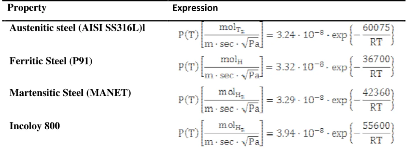
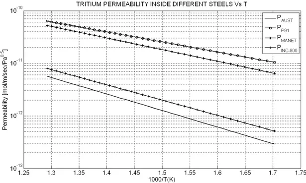
SFR-TPC material properties database ... 48
Modeling of tritium losses and inventories ... 51
Modeling of tritium losses. ... 51
Modeling of Tritium Inventories ... 54
Investigation of the tritium transport mitigation techniques ... 59
Tritium permeation barriers ... 59
Theory of permeation in two-layer membranes ... 60
Various hydrogen/tritium permeation barriers ... 61
Tritium/hydrogen cold traps ... 65
Technical features of an experimental cold trap device: the AMPS cold traps ... 70
Results and discussions ... 73
Introduction ... 73
General description of the Prototype Fast Breeder Reactor (PFBR) ... 74
SFR-TPC numerical input data for the simulation ... 75
Results and discussions without permeation barriers and cold traps ... 79
Results and discussion with permeation barriers and cold traps ... 87
Comparison of the results with various radiological limits ... 95
Validation of the code ... 99
Conclusions and discussions ... 103
INTRODUZIONE E SOMMARIO DEL LAVORO
Uno degli isotopi radioattivi più difficili da contenere all’interno dei reattori SFR (Sodium-cooled Fast Reactors) è il trizio in quanto, essendo un isotopo dell’idrogeno, diffonde prontamente attraverso i materiali strutturali alle temperature operative e conseguentemente può essere rilasciato in ambiente.
Al fine di studiare ed analizzare possibili accorgimenti necessari per ridurre l’entità dei rilasci di trizio in ambiente è stato sviluppato un codice di calcolo in linguaggio MATLAB (SFR-TPC), il quale viene utilizzato per valutare i rilasci di trizio in ambiente e gli inventari di trizio all’interno dei reattori SFR.
Il trizio che viene generato nel core attraverso le fissioni ternarie e l’attivazione del boro, raggiunge quasi interamente il refrigerante primario, attraverso il quale entra nello scambiatore intermedio (IHX); successivamente, permeando attraverso le pareti dei tubi dell’IHX e del generatore di vapore (SG), raggiunge prima il sodio secondario e successivamente il vapore nel loop terziario di power - conversion (generatori di vapore, turbine, condensatori ecc). Il rateo totale di trizio introdotto nel sodio primario dal nocciolo e dalle barre controllo per un reattore di 1000 MWe ammonta a circa 75000 Ci/y.
Al fine di ridurre i rilasci di trizio si possono adottare due principali tecniche: 1) rivestimento (o coating) dei tubi degli scambiatori di calore (IHX e/o SG) di un certo tipo di materiale (in genere ossidi) in grado di ridurre i flussi permeati di un certo fattore PRF (Permeation Reduction Factor), 2) inserimento di trappole fredde (o cold traps) nei rami freddi dei circuiti primari e secondari. Il cold trapping del sodio ha l’obbiettivo di ridurre la solubilità dell’idrogeno (e del trizio) nel sodio tramite raffreddamento, determinandone quindi la precipitazione in una limitata regione “fredda”. Le trappole fredde rispetto al coating dei tubi sono dispositivi ampiamente utilizzati per la loro efficienza, economicità e compattezza. Tuttavia alcune campagne sperimentali sono state condotte con l’obbiettivo di stimare l’attitudine di alcuni acciai a formare uno strato di ossido in grado di ridurre i flussi permeati; ad esempio l’INCOLOY 800 (lega al nickel candidata per la costruzione dei generatori di vapore in questa tipologia di impianti) ha mostrato PRF derivanti dalla propria ossidazione naturale (lato vapore) varianti tra 20 e 400. Per quanto riguarda invece le superfici a
contatto con il sodio, diversi studi hanno evidenziato che alcuni metalli come Fe, Ni e Cr (metalli tipici nell’ossidazione) difficilmente danno origine a ossidi stabili in quanto il sodio costituisce un ambiente riducente. Le pareti a contatto con il sodio vengono quindi conservativamente considerate “pulite” e prive di alcuna barriera antipermeazione (PRF=1).
L’analisi condotta con l’utilizzo del codice SFR-TPC su un reattore di tipologia “a vasca” denominato PFBR (Prototype Fast Breeder Reactor), ha mostrato che, assumendo PRF=1 e PRF=10 per IHX e SG rispettivamente (ipotesi conservative) e, ricircolando nelle cold traps lo 0.05 % della portata totale di sodio fluente nel nocciolo e nei loop secondari con un’efficienza di rimozione media del 80 % (parametri operativi che consentono di rispettare il target progettuale di contenimento delle cold traps), solo circa 1.6 mg/y di trizio (su 3.874 g/y prodotti nel core e rilasciati nel refrigerante primario) raggiungono il ciclo del vapore e vengono conservativamente considerati come rilasci in ambiente. Inoltre, aumentando di dieci volte la portata di sodio nelle cold traps (lo 0.5 % della portata totale di sodio fluente nel nocciolo e nei loop secondari), le attività specifiche di trizio nel sodio primario e secondario allo stato stazionario ammontano rispettivamente a 8 MBq/kg e 0.11 MBq/kg, le quali risultano confrontabili con quelle misurate in alcuni impianti in dismissione simili per tipologia a quello oggetto di studio (PFBR). Ad es. il reattore SuperPhénix ha mostrato attività specifiche di H3 nel Na primario tra 5 e 20 MBq/kg.
Nonostante le ipotesi conservative assunte il dato di rilascio ottenuto non costituisce un elevato rischio radiologico purché si adotti un opportuno set di misure mitigative per il trasporto di trizio (cold traps e barriere alla permeazione derivanti o meno da processo di ossidazione naturale opportunamente controllati).
Chapter 0
Description of an SFR pool-type design
General description of SFR systems
The Sodium-Cooled Fast Reactor (SFR) system is one of six types of plants in Next Generation Nuclear Plant (NGNP). The NGNP [1] is in the pre-conceptual design phase with major design selections (e.g., reactor core type, core outlet temperature, etc.) still to be carried out. SFR features a fast-spectrum reactor and a closed fuel recycle system. The primary mission for SFR is the management of high-level wastes and, in particular, the management of plutonium and other actinides [1]. With innovations to reduce capital costs, the mission can extend to electricity production, given the proven capability of sodium reactors to utilize almost all of the energy in the natural uranium versus the 1% utilized in thermal spectrum systems [1].
The SFR system features a fast-spectrum reactor and closed fuel recycle system. The majority of natural uranium is the isotope making up about 99.3 %. The remaining 0.7 % is , the isotope required for thermal fission in modern light water reactors. The fast neutrons are used to breed plutonium from and these plutonium isotopes then undergo fission to produce heat. Therefore fast reactors can utilize uranium much more efficiently than thermal reactors. Since water acts as a moderator and will slow neutrons out the fast spectrum, liquid metals, such as sodium, are used as coolants in these fast reactors transferring the heat to a power conversion system used to produce electricity.
The primary coolant system can either be arranged in a pool layout schematized in Figure Errore.
Nel documento non esiste testo dello stile specificato.-1 (a common approach, where all primary system components are housed in a single vessel), or in a compact loop layout, favored in Japan.
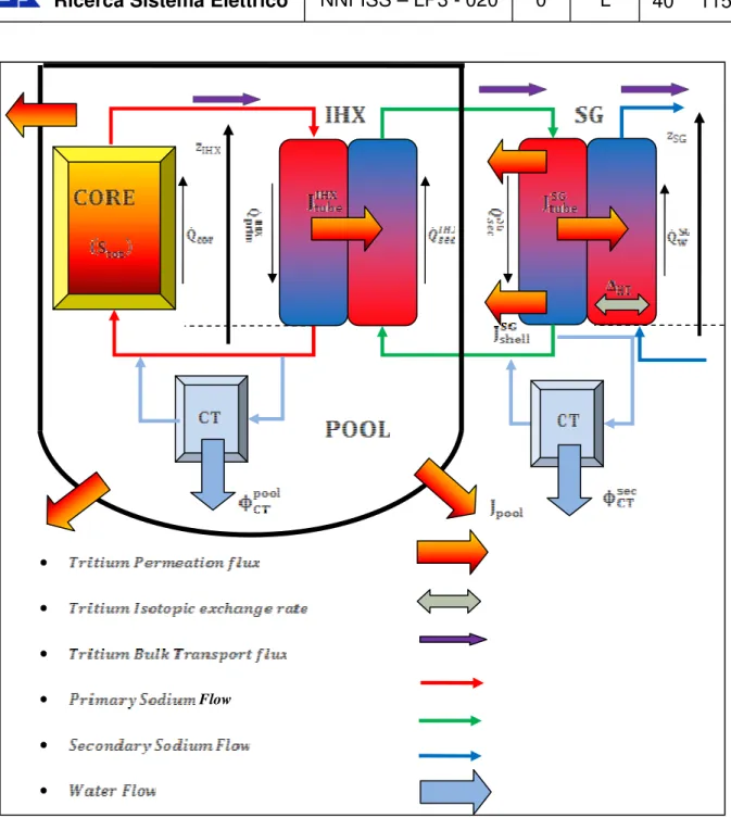
Figure Errore. Nel documento non esiste testo dello stile specificato.-1 SFR pool type design configuration [1] In the pool type design the reactor core, the primary pumps, the IHXs (Intermediate Heat Exchangers) and the DHXs (Decay Heat Exchangers) are all immersed in a pool of sodium coolant within the reactor vessel, so the primary radioactive sodium does not leave the reactor vessel during normal operation. In this way LOCAs (Loss Of Coolant Accidents) affecting the primary sodium are extremely unlikely. The primary pump is totally submerged in the vessel, so the risk of having large sodium pipes under the core level (which could lead the core to become uncovered after a large LOCA) is eliminated. A disadvantage of this configuration is that a larger reactor vessel is required to host the heat exchangers and a larger quantity of primary sodium is needed. Moreover, the reactor vessel requires more complex internal structures.
In the loop type SFR design the primary coolant is circulated through pumps and IHXs in pipes which are external to the reactor tank. The main advantages of this design are: compactness,
easier in-service inspection and maintenance, smaller amount of sodium needed. The big disadvantage of this configuration is the possibility of a sodium leakage, which is much higher than in a pool-type SFR.
The total thermal power generated in the reactor core is exchanged by a set of IHXs in the reactor vessel. IHX is in general a straight tube heat exchanger of counter current shell and tube type. Liquid sodium is circulated through the core using one/two primary sodium pumps. The sodium enters the core and leaves at an higher temperature. The hot primary sodium is radioactive and is not used directly to produce steam, in fact it transfers the heat to secondary sodium through set of IHXs. The non-radioactive secondary sodium is circulated through a certain number of independent secondary loops, each having a sodium pump, a given number of intermediate heat exchangers and of steam generators (SG).
From the tritium analysis point of view, the IHX is a crucial component, since a portion of tritium entering the primary sodium permeates firstly through the IHX pipes walls and then through the SG ones reaching the feed water and escaping into the environment.
Selection of materials for SFR components
In order to perform a tritium transport analysis in SFR systems, some data on materials attitudes to allow tritium transport (i.e. tritium permeabilities and solubilities). For this reason attention will be focused on pool containment, IHX and SG materials.
In SFRs austenitic stainless steels are employed in the entire liquid sodium system even if the temperatures of some components are low enough to use less expensive ferritic steels [2]. Table
Errore. Nel documento non esiste testo dello stile specificato.-1 lists the structural materials selected for major components such as reactor vessel, intermediate heat exchanger (IHX), and piping in currently operating or designed Fast Breeder Reactors (FBRs) all over the world. The grades selected include 304, 304L, 316, 316L, 321, 347 and their equivalents. These steels have also poor creep ductility. In high temperature sodium, austenitic stainless steels have good resistance to general corrosion and localized corrosion.
Thus, for the IHX components, we see that austenitic stainless steels are preferred for sodium operation inside SFR intermediate heat exchanger. This is a precious information from the tritium permeation point of view. The permeability of tritium through a metallic materials is a key
component in a tritium transport analysis. Therefore, when IHX is modeled, we need to keep in mind that austenitic stainless steel are preferred for SFR’s IHXs installation.
Table Errore. Nel documento non esiste testo dello stile specificato.-1 Materials selected in SFRs for major components [2]
Materials selected for SFR steam generator application should meet requirements of high temperature service such as high temperature mechanical properties including creep and low cycle fatigue, resistance to loss of carbon to liquid sodium which leads to reduction in strength, resistance
to wastage in case of small leaks leading to sodium-water reaction and resistance to stress corrosion cracking in sodium and water media [2]. For SFR steam generators, a range of materials starting from ferritic steels (2.25Cr- 1Mo, Nb stabilized 2.25Cr-1Mo, 1Mo (grade 9), Modified 9Cr-1Mo (grade 91)), austenitic stainless steels (AISI 304/316/321) and Nickel alloys (Incoloy 800) were examined [2]. In view of the poor resistance to aqueous stress corrosion cracking (SCC), austenitic stainless steels of 300 series wouldn’t be considered for the steam generator [2]. Incoloy 800 shows better resistance to SCC than austenitic steels, but it is not immune to stress corrosion cracking in chloride and caustic environments [2]. Therefore, ferritic steels are the most preferred for steam generator applications [2] (Table Errore. Nel documento non esiste testo dello stile specificato.-2). Among the ferritic steels, 2.25Cr-1Mo and 9Cr-1Mo steels and their variants were preferred for SFR steam generators.
Table Errore. Nel documento non esiste testo dello stile specificato.-2 Materials selected for steam generator in major SFRs [2]
From the tritium transport analysis point of view, the steam generator represents the second joint between the tritium source and the environment, since it directly belongs to the heat transport
system immediately after the IHX. Thus, a detailed investigation of SG material properties has to be carried out. In conclusion linking past experiences and selection criteria for SG materials, in a tritium analysis applied to SFR systems, Incoloy 800 and ferritic steels would be considered.
Chapter 0
Theoretical aspects of hydrogen isotopes kinetics in
matter
Chemical and radiological properties of tritium
Transport of different chemical species of tritium in the environment (i.e., HT and HTO) is related to physical and chemical processes. Physical processes are bulk transport (tritium moves because of its dissolution inside heat transfer fluids) and diffusional transport (tritium motion is driven by concentration gradient). Reactions and state changes of chemical species are chemical processes [1].
Tritium is a radioactive isotope of hydrogen with the half life of 12.32 years. The nucleus of a tritium atom consists of a proton and two neutrons. This contrasts with the nucleus of an ordinary hydrogen atom and a deuterium atom. Ordinary hydrogen comprises over 99.9%, deuterium comprises 0.02%, and tritium comprises about a of naturally occurring hydrogen (Ref. [4]). The physical and chemical properties of tritium are very close to those of hydrogen [1]. Typically, tritium exists as a form of tritium gas ( ) because of isotope exchange reactions between and [4]. Tritiated water is another common form of tritium. In tritiated water, a tritium atom replaces one of the hydrogen atoms so the chemical form is rather than . Tritium in the environment has three sources: natural production, release from atmospheric weapon tests, and routine or accidental releases from the nuclear industry [1].
Inhalation, ingestion and skin exposure are the three main routes of exposure to tritium for man [1]. The radiological impact of tritium results from the combination of the characteristics and the behavior of the radionuclide. Some parameters enhance the radiotoxicity of tritium: for example, its radioactive half-life relatively long (12.35 years), its uptake by humans is likely to take place and as an isotope of hydrogen, it has a high biological importance [1]. The decay of tritium is given by:
(2-1) The (or electron)'s kinetic energy varies, with an average of 5.7 [1], and a maximum of 19
[1] while the remaining energy is carried off by the nearly undetectable electron antineutrino .
The radiotoxicity of tritium is relatively low; the dose coefficients per unit of incorporation (the effective dose per built-in Becquerel) have been evaluated at for HT (inhalation), for HTO (ingestion or inhalation) [1]. As for other radionuclides, the theoretical risk of death by cancer due to tritium incorporation has been calculated to be incorporated [1]. The World Health Organization (WHO) places the limit at an annual effective dose of 0.1 mSv, corresponding to the daily consumption of tritiated water at a concentration of during a year [1].
Solubility of hydrogen in metals: derivation of the Sievert’s law
Hydrogen dissolves in and permeates through most materials, thus it is important to understand the permeation, diffusion and dissolution of atomic hydrogen in materials in which hydrogen and its isotopes are present.
More recently, these topics have received attention from the hydrogen energy community; hydrogen dissolution and permeation can be significant, especially in liquid metals. Thus, it is also necessary to understand the behavior of hydrogen in these materials, in order to predict the transport mechanisms inside the nuclear heat installations, and to estimate the tritium losses into the environment. Tritium permeation mechanisms are studied mainly in liquid metals for nuclear fusion devices, but in this study the attention is addressed also in liquid metals involved in next generation nuclear power plant, such as liquid sodium.
The Sievert’s law
After crossing the outer surface of a solid, hydrogen moves into the subsurface where it occupies a solution site of the host lattice. There are two parameters characterizing the ability of materials to dissolve gas: the Sievert’s constant and the solubility .
The solubility of a gas in a material is defined as the concentration of the gas dissolved at the chemical equilibrium , under a given pressure and temperature. The concentration of hydrogen in the bulk of the material, in the most general form, is expressed as a function of both temperature and pressure and is defined as [5]:
(2-2) The parameter may be different in different conditions. In dilute solution for diatomic gases, and this is the case of the so called Sievert’s law, and characterizes the
Sievert’s constant. The Sievert’s law can be derived starting from ideal gas law and from basic
thermodynamic relationship relating molar volume , the chemical potential the temperature and the pressure according to the following equations [6]:
(2-3)
(2-4) Substituting Eq. (2-3) into Eq. (2-4), the chemical potential of an ideal gas can be written in the form [6]:
(2-5) Assuming chemical and thermodynamic equilibrium between the diatomic hydrogen molecule (gas phase) and hydrogen atoms in a metal (solid phase) we find the following equilibrium:
(2-6) At chemical equilibrium, the chemical potential of the gas must equal the chemical potential of hydrogen dissolved in the material [6] as follows:
(2-7) In this context we assume that atomic hydrogen dissolved in the material behaves as a dilute solution, thus, integrating the expression reported in Eq. (2-5) between the standard state (defined at
standard temperature and pressure) and the generic thermodynamic state (defined at temperature and pressure ] and ) and considering chemical equilibrium between solid and gas phase (Eq. (2-7)), we obtain the following equation [6]:
(2-8) where is the equilibrium concentration of hydrogen dissolved in the metal lattice and the superscript 0 refers to the standard state. The difference in chemical potential between the standard states is related to the enthalpy of formation of H-atoms in the metal and the entropy of formation [6]:
(2-9) Combining Eqs. (2-8) and (2-9) the concentration of hydrogen that is dissolved in the metal lattice and in equilibrium with the hydrogen gas can be expressed as [6]:
(2-10) Where:
(2-11) The concentration at the chemical equilibrium of hydrogen in metal lattice (or solubility ) can be written in the final form [6]:
(2-12) Where:
(2-13) is the Sievert’s constant (which is a function of temperature) and is called heat of solution. Ideal behavior is a good engineering approximation at elevated temperatures and relatively low pressures [6]. It is important to emphasize that the Sievert’s law is a simplified way to describe the equilibrium mechanism between two different system (gas phase and solid phase), and to relate this equilibrium to the gas partial pressure, which is very important to study the hydrogen isotopes permeation in materials and characterizes the driving force of the permeation. For our purposes it is relevant to determine the Sievert’s constant for all different materials present in the specific type of power plant and through which tritium can move.
Solubility of hydrogen in liquid sodium
Since we are dealing with SFR systems, it would be of relevance to treat, in a theoretical way, all chemical issues regarding presence of hydrogen (and its isotopes), in liquid sodium, especially regarding solubility of hydrogen in sodium.
Na – Na-H binary system exhibits a monotectic reaction, which is a case of a non complete solubility between Na and Na-H system (as shown in Figure Errore. Nel documento non esiste testo dello
stile specificato.-2). The monotectic invariant temperature and the equilibrium hydrogen pressure at that temperature were determined by Skuratov et al. [7] as and , respectively.
Dissolution of hydrogen in sodium can be represented by a Barn-Heber cycle, as shown below [7]:
Figure Errore. Nel documento non esiste testo dello stile specificato.-3 Barn-Haber cycle [7]
The process I is very important to understand the hydrogen (and tritium) impurities removal mechanisms from sodium in SFR (see cold traps in par. 0), while the process III is the basic chemical equilibrium considered for tritium concentration modeling in sodium inside heat transport facilities (e.g. the core, the Intermediate Heat Exchanger and the Steam generator) assuming that tritium dissolves in ionic form in liquid form, and a chemical equilibrium between dissolved tritium ions and tritium in gaseous phase.
Solubility data of hydrogen in liquid sodium
Below the monotectic temperature (see Figure Errore. Nel documento non esiste testo dello stile
specificato.-2), hydrogen dissolves in sodium up to a concentration beyond which solid sodium hydride saturated with sodium metal precipitates. Thompson, based on a solvation model, postulated that hydrogen in solution would be present as hydride ion [7]. In the single phase region consisting of liquid sodium (with dissolved hydrogen in it), the following equilibrium with gaseous hydrogen exists [7] (process III of Born – Heber cycle reported in Figure Errore. Nel documento non
esiste testo dello stile specificato.-3):
(2-14) and the equilibrium constant is determined by [7]:
(2-15) where is the activity of hydrogen in sodium and is the activity coefficient and
sodium can be expressed by means of concentration in ion form ( ), and activity coefficient ( ) as follows:
(2-16) For the dilute solutions of hydrogen in sodium, Henry's zeroth order law can be applied [7]. i.e. is finite. Under these conditions, Sievert’s constant, would remain constant. For a given temperature, the concentration range up to which this law is applicable can be ascertained from the experimental data.
Data on solubility of hydrogen in liquid sodium have been reported by several workers. These measurements can be broadly classified under two categories: (i) measurements using manometric techniques with sodium contained in static pots or sealed capsules and (ii) measurements in large sodium loops [7]. In the first category of experiments, techniques based either on absorption of hydrogen by sodium or desorption of hydrogen from Na-NaH samples of known compositions were used. In the second category of experiments the equilibrium hydrogen pressures were determined using hydrogen monitors [7]. Solubility data reported by various authors are shown in Figure Errore. Nel documento non esiste testo dello stile specificato.-4 and the details of techniques used by them are reported in Ref. [7].
Since solubility here is defined as a function of temperature, we are interested in the empirical equations obtained by different authors. Not all solubility relations are reported here, but only derived by Vissers et. al (Eq. (2-4)) and that obtained by Wittingham (Eq. (2-5)) defined as follows:
(2-17) (2-18) The above equations identify the solubility (or the concentration at the chemical equilibrium) of hydrogen in sodium for low hydrogen partial pressure, which implies that the dependency of the solubility on hydrogen partial pressure is quite low and therefore it is defined only as a function of temperature. However, for modeling tritium transport in SFRs the above equations are not relevant, because we are dealing with sodium in which a certain tritium amount is dissolved, and since tritium partial pressure is the driving force of permeation through structural materials, we need a mathematical tool that correlates dissolute tritium concentration and partial pressure, which is the case of the Sievert’s constant.
Sievert’s constant data of hydrogen in liquid sodium
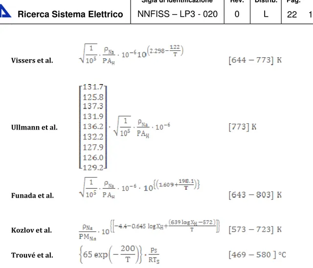
Hydrogen Sievert’s constant in sodium can be evaluated from nine main author’s data [7]. • Davies et al; • Meacham et al; • Pulham et al; • Witthingam et al; • Vissers et al.; • Ullmann’s et al; • Funada et al.; • Kozlov et al; • Trouvé et al.
All Sievert’s constant data reported in Table Errore. Nel documento non esiste testo dello stile
Figure Errore. Nel documento non esiste testo dello stile specificato.-5 Hydrogen Sievert's constant in liquid sodium Vs 1000/T [K]
Sievert’s constant data for Na-H system reported in the literature ([7],[8]) are listed in Table Errore. Nel documento non esiste testo dello stile specificato.-3, with the temperature range of the measurements. Author Temperature Davies et all Meacham et al. Pulham et al. Witthingam et al
Vissers et al.
Ullmann et al.
Funada et al.
Kozlov et al.
Trouvé et al.
Table Errore. Nel documento non esiste testo dello stile specificato.-3 Hydrogen Sievert's constant data for liquid sodium1
where PAH and are the hydrogen atomic weight and the liquid sodium density
respectively. The reported data show that variation of Sievert’s constant is negligibly small in the temperature range of 603-843 K and in order to visualize more clearly all listed data, in this case they are reported in a linear scale plot instead of a log scale plot. The parameter , , and appearing in Table Errore. Nel documento non esiste testo dello stile specificato.-3 are the sodium density,
the hydrogen atomic weight (these two last terms were necessary in order to convert all Sievert’s constant data in the same units) the standard pressure and the standard temperature respectively.
Influence of oxygen content on hydrogen Sievert’s constant data.
Sievert’s constant experiments clearly indicate an increase in its measured values with the increasing of dissolved oxygen concentration [7]. Presence of oxygen impurity would lead to an interaction with dissolved hydrogen, which can be represented by the following equilibrium [7]:
(2-19) According to this chemical equilibrium reaction, The total hydrogen concentration is given by [7]:
(2-20) where is a thermodynamic equilibrium constant (function of temperature) and is the total oxygen concentration in sodium. Dissolved hydrogen concentration in sodium under equilibrium with a known hydrogen partial pressure would then increase with oxygen concentration in sodium. Since Sievert’s constant, in Eq. (2-16) is applicable only for and not for , data derived from experiments in oxygen contaminated sodium would result in an apparent increase in Sievert’s constant with increase in oxygen concentration [7], as confirmed by the next relation obtained by introducing an apparent Sievert’s constant that takes into account the oxygen content in sodium [7]:
(2-21) Using Eq. (2-16) we obtain [7]:
Figure Errore. Nel documento non esiste testo dello stile specificato.-6 Variation of Sievert’s constant with dissolved oxygen [7]
Taking to be independent of temperature (as a first approximation), arithmetic mean of the Sievert’s constant measured at known values of oxygen concentration in sodium are plotted in Figure Errore. Nel documento non esiste testo dello stile specificato.-6. The data in Figure Errore. Nel documento non esiste testo dello stile specificato.-6, fitted to a straight line by the method of least squares, can be expressed by the following equation [7]:
(2-1) The dependence of Sievert’s constant is reported in Figure Errore. Nel documento non esiste testo dello stile specificato.-6 :
This variation of Sievert’s constant with oxygen concentration in sodium should be taken into account while estimating tritium permeation fluxes through heat exchangers, which is the target of this study. For a tritium permeation model the Sievert’s constant is key parameter, and it is necessary to pay attention to it. However, for our purposes the oxygen content is not considered, but can be used in order to take into account of all incident parameters (such as oxygen content).
Equilibrium hydrogen pressure over Na(l) – NaH(s)
As already illustrated at the beginning of this section, the hydrogen dissolved in sodium can origin solid sodium hydride NaH(s) (see process I of Born – Heber cycle reported in Figure Errore.
Nel documento non esiste testo dello stile specificato.-3). The hydrogen pressure over the two phase Na(l) - NaH(s) mixtures, represent the following equilibrium occurs:
(2-2) This pressure has been measured as a function of temperature by several workers. Measurements have been carried out by determining hydrogen pressures over either solid NaH (i.e., decomposition pressures) and liquid sodium covering a wide temperature range of 373 to 1032 K [7] (monotectic temperature in Na - NaH system is 906.2 K [7]). The experimental results are characterized by Arrhenius type relations as those reported for hydrogen solubility in Eqs. (2-4) and (2-5); these results are reported in Ref. [7]. For our purposes they are not so relevant, but this brief discussion was meant to make the reader to understand that, if the above chemical equilibrium occurs (when hydrogen is not dissolved in liquid sodium in the atomic form, according to the solvation model represented by chemical equilibrium (2-1)), hydrogen can be removed as a solid impurity from sodium by means of solid sodium hydride (NaH) precipitation reducing the sodium temperature and thus, reducing its solubility in liquid sodium. This mechanism is verified inside the sodium cold traps (see par. 0), that are needed in order to remove significant tritium quantities from primary and secondary sodium, in order to reduce tritium losses and inventories.
Sievert’s constant data of hydrogen in various liquid metals
Since Sievert’s constant is a crucial parameter also in fusion reactors (where tritium is the fuel and is produced by breeding reactions inside liquid lithium or eutectic alloy lead-lithium), it could be interesting to report in the same Arrhenius plot the hydrogen Sievert’s constant in sodium and that of lithium and lead-lithium, which are two liquid metals studied to be used as tritium breeders in fusion reactors (see Figure Errore. Nel documento non esiste testo dello stile specificato.-7).
In order to have a good data visualization not all curves reported in Figure Errore. Nel
documento non esiste testo dello stile specificato.-5 are plotted, but only the maximum and the minimum for each liquid metals (Aiello et al [9] and Chan et al [10] for lead-lithium, Trouvé et al [8] and Funada et al [7] for liquid sodium, Moryama et al [11] and Smith et al [12] for liquid lithium respectively).
This plot is crucial for our Sievert’s constant discussion. In fact the first consideration to be performed regards the position in this plot of hydrogen Sievert’s constant in sodium. As shown in Figure Errore. Nel documento non esiste testo dello stile specificato.-7 the sodium is located between the liquid lithium, which occupies the top of the plot, and the lead-lithium which is located in the bottom. From these considerations we can affirm that hydrogen permeation in sodium is not worrying like in lead lithium, but it is more worrying that those concerning the lithium. Similarly, the same considerations can be made discussing about the tritium inventory problem, which is less problematic then that in liquid lithium, but more than that in lead lithium. These considerations allow us to conclude that Sievert’s constant is the key parameter which correlates the driving force of tritium losses into the environment (the partial pressure), and the tritium inventory (or the concentration), which are the fundamental parameters in a tritium transport assessment of a plant, whose objective is to estimate the radioactivity leaving the plant (for people and environmental matrix safety), and the radioactivity staying in the plant during normal power production operations.
Figure Errore. Nel documento non esiste testo dello stile specificato.-7 Hydrogen Sievert's constant in different liquid metals Vs 1000/T [K]
Modeling of permeation
In order to find out the main mechanisms of hydrogen permeation and the techniques adopted for solubility and diffusivity measurements a permeation model is needed. In fact the Sievert’s constant determination can be developed from indirect calculation of an hydrogen permeated flux in a certain volume [9]. In the simplest model of hydrogen permeation through a membrane, three processes have to be considered:
• The chemisorption, where hydrogen molecules in the gas phase dissociate on the solid material surface providing adsorbed atoms which may diffuse into the solid;
• The desorption by which adsorbed atoms recombine and are released as molecules; • The diffusion, by which hydrogen atoms move through the membrane.
The first two of these processes are known as “surface processes” and under certain conditions (i.e. low partial pressures [6]) they may completely control the permeation rate. Under other conditions, instead, diffusion may be the limiting factor. In the first case the process is called “surface – limited permeation”, while the second “diffusion – limited permeation”. When surface conditions modify the kinetics of hydrogen transport, the square root dependence of pressure is often lost [6]. Very low pressure (<10 Pa) also precludes the square root dependence on pressure and diffusion-controlled transport [6]. Moreover, the apparent changes in hydrogen transport appear to be the result of changing the rate-controlling step from lattice diffusion to a surface process (such as adsorption and dissociation), and surface layers do not change the intrinsic hydrogen permeability of the material. There are two limiting cases of permeation:
• Diffusion – limited model; • Surface – limited model.
In this paragraph only the diffusion – limited model is going to be examined by the mathematical point of view.
Diffusion – limited model
Hereafter is considered the hydrogen permeation through a membrane in which the characteristic time of the surface effects (i.e. the time relevant for gas adsorption in the high pressure side and recombination in the low pressure side) is negligible with respect to the time of diffusion through the solid.
The membrane of thickness , with surfaces at and , diffusion coefficient independent on hydrogen concentration, initially does not contain dissolved hydrogen. Then at time one side of the membrane is pressurized with hydrogen at concentration . Assuming suitable initial boundary conditions the problem is mathematical described by 1-D time dependent diffusion equation with no volumetric source inside the domain. The overall mathematical relation is given by [13]:
The analytical solution with the reported initial boundary condition has derived from Eigen value problem and the solution is found using Fourier’s series and adopting the separation of variables technique. Thus, the concentration is a function of two variables and and is defined as [13]:
(2-4) The second boundary condition in Eq. (2-3) means that the exit surface is always in contact with a negligible hydrogen pressure with respect the high pressure side. Using Fick’s law, the gas flux from the exit surface as a function of time can be calculated as [13]:
(2-5) Considering also the formulation of a certain hydrogen concentration at the equilibrium formulated by the Sievert’s law (Eq. (2-12)), it is possible to express the value of parameter by means of hydrogen partial pressure in the high pressure side and the hydrogen Sievert’s constant inside the membrane material; thus the total flux coming out from the exit surface is characterized by the following expression [13]:
(2-6) At steady state (i.e. ) Eq. (2-6) becomes:
(2-7) which is known as the Richardson’s law, where:
(2-8) is defined as the permeability of the material. Since and vary with temperature in an Arrhenius manner, also can be written as:
(2-9) where is the activation energy for permeation which is the sum of that of diffusion and solubility. This last expression is very indicative for a good intuition of hydrogen transport mechanisms, because it indicates that in order to have permeation through a certain solid
material, the hydrogen atom has to dissolve in the host material and diffuse through it; thus, by the numerical point of view the this is confirmed by the product of solubility and diffusivity (Eq. (2-8)). In conclusion, when a wall with a thickness and a permeability is subjected to an high tritium partial pressure and to a lower one on the opposite side, the 1-D steady state permeated flux through the wall assumes the general form expressed in the following equation:
(2-10)
Theoretical aspects of hydrogen isotopes in water
The steam/water system in nuclear reactors in general may contain . Hydrogen inside water could be present both in ionic form (natural dissolution dependent on the water pH), or in molecular form , which may be or dissolved naturally or added for corrosion and safety problems [15]. The tritium atoms coming from secondary sodium inside the SG, enters in water and interacts chemically with hydrogen dissolved in . In this regard, since pure water is said to be neutral with a pH close to 7.0 (at which corresponds an ionic hydrogen concentration of ), the amount of ionic and molecular hydrogen dissolved in water is supposed to be much larger than that of tritium coming from a generic high pressure region (i.e., secondary sodium in SFRs); thus, all tritium atoms coming from this region in atomic form T recombines in molecular form and bounds chemically with dissolved molecular hydrogen . Therefore, all atomic tritium atoms entering into the water via permeation, become atoms of , according to the following chemical equilibrium reaction:
(2-11) Since the equilibrium constant is quite large [14] (is a product-shifted chemical equilibrium), the HT isotopic exchange rate of this equilibrium will be not considered, and therefore only the permeable species HT (between the two gaseous and permeable species HT and T2) will be
considered in water inside SFR’s steam generators.
Tritium in liquid water
The mass transfer of tritium through the steam generator tubes is assumed to be driven by the partial pressure in secondary sodium and the HT partial pressure in the water side. The HT
partial pressure inside water is controlled by two thermodynamic equilibria: a chemical equilibrium, in the liquid phase, among the species , , and and a gas-liquid equilibrium between HT in liquid ( ) and HT in gas ( ).
In the cooling water, the following equilibrium due to the addition (dissolved in water or produced by corrosion of structural materials) is considered [15]:
(2-12) and the corresponding equilibrium constant is [15]:
(2-13) and the HT concentration in water can be calculated by [15]:
(2-14) where is the molar tritiated water molar concentration and is the solved molar concentration.
A system consisting of two components (HT and water) and two phases (gas and liquid) has been considered. The equilibrium between the HT in the gaseous phase ( ) and the HT dissolved in the liquid ( ) is expressed by equating the fugacities [15]:
(2-15) and:
(2-16) where: is the HT fugacity in the gaseous phase, is the fugacity in the liquid phase, is the fugacity coefficient, is the partial pressure [Pa], is the Henry constant , is the activity coefficient , and is the HT molar concentration in the liquid phase. in the limit of ideal gas the fugacity is coincident to the pressure, hence we can state that the fugacity coefficient is almost equal to one . The partial pressure of tritium HT inside liquid water becomes:
(2-17) There are several ways of describing the solubility of a gas in water. Usually the Henry’s law constant is defined as [16]:
(2-18) Here, is the concentration of the a species in the aqueous phase and is the partial pressure of that species in the gas phase. If refers to standard conditions ( ) it will be denoted as . A simple way to describe Henry’s law [16] as a function of temperature is:
(2-19) where is the enthalpy of solution (the Henry’s constant written in the form of Eq. (2-18) was observed to decrease with temperature increasing [17] and, as a consequence, the hydrogen solubility in water decreases with temperature increasing).
Tritium in vapor water
When water inside SG tubes evaporates, the constitutive relation between HT pressure and HT concentration is different. In fact, in case of superheated steam (vapor mass fraction =1), the water is considered to be treated as a single phase gas, and the concentration is proportional to the partial pressure inside steam, according to Dalton’s law, which is related to ideal gas law. In a mixture of different gas with a given pressure , the total pressure of mixture is given by the summation of single gas species pressure as follows:
(2-20) and the partial pressure of single species is given by:
(2-21) where is the molar fraction of species i component in the total mixture of component. If we consider a system composed by a mixture of superheated water , tritiated hydrogen , and tritiated water , the HT partial pressure inside steam is given by:
(2-22) where is the molar fraction of HT inside steam, and is the steam pressure inside the SG. Since we are interested in HT concentration expressed in recommended unit
(2-23)
which correlates molar fraction to the volumetric concentration as:
(2-24)
Tritium isotope exchange rate
Chemical equilibrium of the isotope exchange reaction (2-12) is characterized by the equilibrium constant defined as follows:
(2-25) where:
• is the chemical equilibrium constant of reaction;
• is the molar flow rate of species at the chemical equilibrium concentration ;
• is the molar inlet flow rate of species ;
• is the amount of conversion rate by reaction (2-12).
As reported in Chapter 3, the term is quite important because it enters in the HT and HTO balance equation (for HT species is a sink term whereas for HTO species is a source term), and it has to expressed as a function of HT and HTO concentrations, starting from values of and inlet water and hydrogen molar flow rate.
Since we pointed out that hydrogen content in water is given by corrosion considerations, the dissolved hydrogen concentration in water at the SG inlet is supposed to be fixed as an input data.
Relationships between tritium partial pressures and concentration
The objective of this section is to summarize all constitutive equations correlating the tritium partial pressure and the concentration depending on the matter tritium is present. This operation is
needed in order to insert all permeation fluxes and in isotope exchange rate into tritium mass balance equations (see next chapter). As described in previous section chemical equilibrium tritium concentration is characterized by different expressions depending on the case in which tritium is dissolved in sodium (Sievert’s law), in liquid water (Henry’s law) and in superheated steam (Dalton’s law).
As already mentioned the tritium partial pressure is the driving force of permeation, thus the permeation fluxes entering the mass balance equation must be expressed as a function of concentrations (which are the mathematical unknowns of the problem), but must take into account that tritium moves from and high partial pressure region to a lower one.
The constitutive relationships between tritium chemical equilibrium concentration and tritium partial pressure are summarized and reported in Table Errore. Nel documento non esiste testo dello stile
specificato.-4, where , , and are the Sievert’s constant of hydrogen in sodium, the Henry’s constant of hydrogen in water, the steam pressure and the molar volume of steam respectively.
Equilibrium Concentration Dissolution Fluid
Liquid sodium Liquid Water Steam
Table Errore. Nel documento non esiste testo dello stile specificato.-4 Constitutive relations of tritium concentration for different dissolution fluids
After this theoretical discussion, all ingredients necessary to develop a complete tritium permeation mathematical model were described and discussed.
Chapter 0
Development of a computational code for tritium
transport analysis in SFRs
Introduction
The expectation that tritium contamination of plant installation in SFRs will be a significant design issue was confirmed [18]. Thus, a tritium transport model in the SFR design phase is required in order to estimate the total amount of tritium released into the environment and circulating inside the plant. In fact the model is applied to the overall SFR plant, considering all tritium transport processes inside nuclear plant installations and studying systematically tritium transport in each components. The objective in this work in fact is exactly to simulate tritium transport behavior in SFR components (according to SFR reference configuration reported in Figure
Errore. Nel documento non esiste testo dello stile specificato.-8) and to predict tritium quantities in different SFR devices by means of solving mass conservation laws with computational tools (such as MATLAB packages).
In literature, different tritium permeation codes for SFRs are available, such as those developed by Kumar in 1974 [19] and by Kozlov et al. in 2005 [20], while more recently another computational code (the TPAC code) was created for Very High Temperature Gas Reactors [4]. In this chapter will be illustrated the computational code SFR-TPC (developed in the academic contest [21]) which is built to evaluate tritium losses and inventories from and inside an SFR system. This
code is essentially inspirited, by the computational and mathematical structure point of view, to the above mentioned codes.
Tritium transport mechanisms in SFRs
One potential problem of using SFR is tritium permeation from the primary coolant through heat exchangers into the environment. In SFRs tritium mostly comes from ternary fission of the fuel and neutron capture reactions inside boron-containing materials [22], such as control rods and neutron flux shielding blocks.
Tritium that enters in the primary coolant will be circulated or permeated to the secondary coolant through the intermediate heat transfer loop. The permeated tritium, successively, enters the product steam/water into steam generator through heat exchanger surfaces. The tritium transport paths in SFRs are shown in Figure Errore. Nel documento non esiste testo dello stile specificato.-8. The mechanisms of tritium transport are mainly diffusion, permeation and bulk transport.
Figure Errore. Nel documento non esiste testo dello stile specificato.-8 Tritium transport pathways scheme in a notional two loops heat transport system
As an isotope of hydrogen, tritium is able to diffuse through the cladding and structural materials and especially through the walls of heat exchangers so that in SFRs, where the temperatures are higher than in water reactors, tritium is highly mobile [22]. This means that, in terms of plant operation and design, it is important to be able to predict the distribution of tritium in SFRs so that amounts of tritium released can be estimated with some certainty at the design stage and counter-measures can be taken if the levels are too high.
In a reactor system tritium escapes from the primary sodium:
• into the argon cover gas where the equilibrium is assumed to be instantaneous;
• by diffusion through the walls of the heat exchangers into the secondary sodium circuits; • into the interspace gas between the vessels, by diffusion through the steel of the vessel and
pipework;
• by crystallization of sodium tritide, or by isotopic exchange in the cold traps (SFR devices necessary to control hydrogen and tritium level as well in primary and secondary coolants, as reported in next chapter);
• by radioactive decay.
In order to calculate at any point in time the tritium concentration in various parts of the circuit a mass-balance of sources - losses = accumulation, has to be established for all the important media of the plant. A typical scheme for an SFR reactor (e.g., Super-Phénix) is illustrated in Figure
Errore. Nel documento non esiste testo dello stile specificato.-9 and the types of species involved are shown in Table Errore. Nel documento non esiste testo dello stile specificato.-5:
Figure Errore. Nel documento non esiste testo dello stile specificato.-9 Schematic representation of a pool reactor [22]
Medium Type Hydrogen species Tritium
Cover gas dissolved molecules H2 HT
Water dissolved molecules H2O HTO
Sodium dissolved ions H- T
Cold traps crystallized molecules NaH NaT
Table Errore. Nel documento non esiste testo dello stile specificato.-5 Type of hydrogen species involved in SFR media [22]
Summary of the SFR-TPC code
The SFR-TPC code solves the tritium 1D time dependent mass balance equation for species (with i = T-, HT and HTO) into fluid (with j = primary sodium, secondary sodium and water) inside the component (with k = core, IHX and SG) and computes the tritium concentrations, characterized by the following concentration functions:
• concentration inside core sodium (lumped parameter) ;
• concentration inside primary sodium along IHX heat transfer coordinate ;
• concentration inside secondary sodium along IHX heat transfer coordinate ;
• concentration inside secondary sodium along SG heat transfer coordinate ;
• HT and HTO concentrations inside water along SG heat transfer coordinate . In water/steam system different isotopic were considered and the 1D time dependent concentration for both species were calculated.
Once the concentrations listed above are calculated, the code proceeds with a post elaboration, evaluating tritium losses and inventories, which are the objective of the code. In particular, the tritium losses are given by the following terms:
• total tritium losses through SG shell surfaces ; • total tritium losses through pool surface ;
• total tritium permeation rate into steam/water bulk through SG pipes walls ; • total tritium losses (sum of all losses tritium terms listed above) .
In the tritium losses computation, it was assumed that all tritium amount entering into the steam cycle permeating through the SG pipes is considered totally lost into the environment.
• total tritium inventory inside IHX’s steels (tube and shell steels) ; • total tritium inventory inside SG’s steels (tube and shell steels) ; • total tritium inventory inside the primary sodium ;
• total tritium inventory in secondary sodium of a single heat transfer loop (sum of secondary sodium in IHXs of a single loop and secondary sodium in SGs of a single loop) ; • total tritium inventory in water/steam of a single heat transfer loop (sum of steam/water
present in all SGs of a single heat transfer secondary loop) . • total tritium inventory (sum of all losses tritium terms listed above) .
Figure Errore. Nel documento non esiste testo dello stile specificato.-10 Sample scheme for Tritium analysis inside a SFR plant
The following phenomena are taken into consideration in this code:
• Mass balance of the species ( in sodium and steels, and in steam/water); • Nuclear production inside the core via ternary fissions and neutron capture reactions; • Tritium transport via bulk transfer with process coolants;
• Tritium permeation through the heat transfer surface;
• Isotope exchange between tritium containing and hydrogen containing chemicals:
• •• • • •• • • •• • • •• • Flow • •• • • •• •
• Nuclear decay.
SFR-TPC code performs the tritium transport analysis for two different notional steam generator configurations:
1) once through straight tube IHXs supplying once through straight tube steam generators (SG) in the secondary circuit;
2) once through straight tube IHXs supplying once through helicoidal tubes SGs in the secondary circuit.
After this qualitative discussion, and observing the reference configuration of an SFR plant reported in Figure Errore. Nel documento non esiste testo dello stile specificato.-10, a quantitative approach has to be performed, in order to treat, theoretical speaking, all physical processes related to tritium transport mechanisms, summarized as:
• • •
• tritium source inside primary coolant ; • • • • tritium permeation , , , ; • • •
• tritium isotopes exchange .
Tritium sources in SFRs
As already mentioned, the three main sources of tritium in SFR systems are: • the fuel via ternary fission (both thermal and fast fissions);
• the boron carbide (B4C) control and shielding rods;
• the impurities in the sodium, e.g. lithium.
Tritium birth from ternary fission.
Tritium is formed by ternary fission in an SFR core with the reported yields typically ranging from about 0.8 to atoms/fission, depending on the fissile nuclide and the neutron flux spectrum [23]. The available tritium yield data are summarized in Table Errore. Nel documento non
Table Errore. Nel documento non esiste testo dello stile specificato.-6 Tritium Yield from ternary fission [23] The yields from thermal fissioning of and are reasonably well known. However, the yields from fast fissioning are not well known; reported yields from the fast fissioning of are one order of magnitude greater than from the thermal fissioning of and and from the fast fissioning of (see Table Errore. Nel documento non esiste testo dello stile
specificato.-6). Since most of fissioning in an SFR core is from fast fissioning [24], this uncertainty in the fast fission yields introduces a nontrivial uncertainty in the total core production of tritium from ternary fission. However, as a first approximation, we can assume that the tritium production rate from ternary fission inside the fuel is directly proportional to neutron the fluxes, the fission cross section and the tritium yields of different uranium and plutonium isotopes.
Since the calculation of the source term is subjected to a large number of uncertainties and lacks of precise and suitable neutronic data, some literature data on tritium source from fuel ternary fission are available to estimate the tritium generation rate. In fact, the specific tritium production rate from SFR fuel is expected to be of the order [22], which means
that a 1000 MWe (assumed to be operated at 2500 MWth) generates 4.13 g/y of tritium by means of
ternary fissions. Thus, assuming this specific generation rate from ternary fission , the total tritium generation rate inside the fuel at a given thermal power is given by:
(3-1) Hence, in SFR-TPC code the source term is calculated only using the thermal power, provided as an input data.
Tritium birth from boron activation.
The adopted approach to estimate the tritium source inside control and neutron flux shielding control rods, is similar to that adopted for fuel tritium source estimation.
The neutron capture reactions involved in the tritium production from boron are the following reactions
(3-2) (3-3) (3-4) As it is possible to see, tritium may be produced directly from boron capture (3-2), or indirectly by producing firstly atoms (3-3), and then, by means of neutron capture of (3-4), tritium atoms are produced.
Estimation of the tritium production rates in B4C control rods is approximate because of
incomplete information on radial dependence of flux and neutron spectrum, and on the quantities of boron involved [22]. As done for tritium source estimation inside SFR fuel, some studies [16,22] report the specific tritium production rate inside boron control rods , which is supposed to be approximately of order of
. Combining , one might be induced to point out that the dominant contribute comes from boron activation. Actually, this is not true, because the important parameter is characterized by the portion of tritium generated inside core materials (boron or fuel) entering the primary coolant, which is the total release rate in the primary sodium as illustrated in par.
However, the total tritium production rate from boron activation is calculated as performed in Eq. (3-1), as follows:
(3-5)
Tritium birth from sodium impurities activation.
Restrictions placed on the lithium content of reactor-grade sodium makes the yield from this source relatively unimportant, however the major reactions include the reaction reported in (3-4) and:
(3-6) specific tritium production rate from lithium impurities should be less than 2
. Once again. the total tritium production rate coming from lithium impurities is given by:
(3-7)
Tritium release rate into the primary coolant
The expected tritium generation rates in different media reported and discussed in last three paragraphs are summarized and listed in Table Errore. Nel documento non esiste testo dello stile specificato.-7.
Table Errore. Nel documento non esiste testo dello stile specificato.-7 Expected tritium generation rates in different media [22]
The appearance of tritium in the SFR primary coolant occurs by escape of fission-generated tritium from fuel rods and by neutron activation of boron and impurities in contact with the coolant. The escape of fission-product tritium from fuel rods can occur through cladding defects, but more importantly, by permeation of the stainless steel cladding by elemental tritium. The latter mechanism is expected to result in release of nearly all the fission-product tritium into the primary coolant [22], whereas a little portion of 20 % of that born in the control rods may be released [25].
According to values listed in Table Errore. Nel documento non esiste testo dello stile specificato.-7 the contribution of impurities is negligible compared to that coming from fuel and control rods. Thus, considering the specific production rates discussed in the above three paragraphs, the total specific tritium source released into the sodium coolant is expected to be
,
and the total tritium source released into the primary sodium, is defined as:(3-8) A 1000 MWe SFR reactor gives a total generation rate of 7.75 g/y, which characterizes
another confirm that tritium is a concern in SFRs. To keep the release as low as practicable, the cold traps will be required to remove at least 90 % of this tritium burden.
Numerical analysis of tritium transport in SFRs
In order to find the concentrations listed in the previous paragraph, a mass balance equations for each concentration functions is needed. Thus, SFR-TPC must be able to solve a system of partial differential equations (PDEs) where the unknowns are the concentrations and where all terms entering the equations are characterized by all tritium fluxes participating to the mass balances (see Chapter 2) and which must be expressed properly as a function of these concentrations. Moreover, since permeation fluxes are proportional to square roots of partial pressures (see Eq. (2-10)) and since in case of tritium dissolved in water, the HT partial pressure and the HT concentration are proportional (see Table Errore. Nel documento non esiste testo dello stile specificato.-4), the tritium permeation flux through SG pipe walls is proportional the square root of the HT concentration. Thus, the problem is characterized by a system of non-linear PDEs and therefore, SFR-TPC adopts a numerical approach to solve mass balance equation for each concentration functions listed above discretizing the control volume into a set of finite volumes (FVs) and the choice of numerical method was addressed to the Finite Volume Method (FVM), performing an integral balance inside the h finite volume of the fluid (with j = primary sodium, secondary sodium or water) inside the component (with k = IHX or SG). This FV (which is the control volume of the spatial domain) is obtained discretizing volume of the fluid j inside the heat exchange k into a certain number of finite volumes ( ), as reported in Figure Errore. Nel documento non esiste testo dello stile specificato.-11.
In this representation is reported only the case in which k = IHX and j = primary sodium and secondary sodium, where a discretization length derived from a discretization of the total IHX heat transfer length into parts gives a discretized primary sodium volume and a secondary sodium one wrapped into the IHX shell with a diameter .
The SFR-TPC basically solves the continuity mass balance equation calculating the concentration inside the h FV for the tritium species i (with i = T-, HT and HTO) into the coolant j (with j = primary sodium, secondary sodium and water), inside the component or heat exchanger k (with k = core, IHX and SG) expressed in the most general form for the concentration as follows:
(3-9)
where:
• is the inlet volume flow rate of fluid inside the FV , coming from FV ;
• is the outlet volume flow rate of fluid from the FV ; • is the decay constant of tritium;
• is the total tritium release rate into the primary coolant (see Eq. (3-8));
• is the permeation flux into the FV h of the fluid j inside the component k through the discretized permeation area (see Eq. (2-10));
• is the isotope exchange rate of the chemical equilibrium (see Eq. (2-25) and par. 0), thus is present only in mass balance equations for tritium in water (HT and HTO species).
![Figure Errore. Nel documento non esiste testo dello stile specificato.-2 Phase diagram of Na – Na-H system [7]](https://thumb-eu.123doks.com/thumbv2/123dokorg/5621492.68556/17.892.274.607.469.1015/figure-errore-documento-esiste-specificato-phase-diagram-system.webp)
![Figure Errore. Nel documento non esiste testo dello stile specificato.-4 Solubility of hydrogen in sodium [7]](https://thumb-eu.123doks.com/thumbv2/123dokorg/5621492.68556/19.892.123.759.664.1081/figure-errore-documento-esiste-specificato-solubility-hydrogen-sodium.webp)
![Figure Errore. Nel documento non esiste testo dello stile specificato.-5 Hydrogen Sievert's constant in liquid sodium Vs 1000/T [K]](https://thumb-eu.123doks.com/thumbv2/123dokorg/5621492.68556/21.892.129.746.168.570/figure-errore-documento-specificato-hydrogen-sievert-constant-liquid.webp)
![Figure Errore. Nel documento non esiste testo dello stile specificato.-6 Variation of Sievert’s constant with dissolved oxygen [7]](https://thumb-eu.123doks.com/thumbv2/123dokorg/5621492.68556/24.892.170.715.165.599/figure-errore-documento-specificato-variation-sievert-constant-dissolved.webp)
![Figure Errore. Nel documento non esiste testo dello stile specificato.-7 Hydrogen Sievert's constant in different liquid metals Vs 1000/T [K]](https://thumb-eu.123doks.com/thumbv2/123dokorg/5621492.68556/27.892.107.788.170.652/figure-errore-documento-specificato-hydrogen-sievert-constant-different.webp)
![Figure Errore. Nel documento non esiste testo dello stile specificato.-9 Schematic representation of a pool reactor [22]](https://thumb-eu.123doks.com/thumbv2/123dokorg/5621492.68556/37.892.235.664.595.835/figure-errore-documento-esiste-specificato-schematic-representation-reactor.webp)