LEADER Project - Work Package 5
Deliverable DEL022
Report on the results of analysis of DEC events for
the ETDR (ALFRED)
Compiled by
G. Bandini (ENEA)
M. Polidori (ENEA)
with the contributions from:
E. Bubelis (KIT-G)
M. Schikorr (KIT-G)
A. Lázaro (JRC-IET)
K. Tuček (JRC-IET)
A. Flores y Flores (JRC-IET)
M. M. Stempniewicz (NRG)
P. Kudinov (KTH)
K. Kööp (KTH)
M. Jeltsov (KTH)
Y. Zhang (PSI)
K. Mikityuk (PSI)
G. Geffraye (CEA)
D. Kadri (CEA)
R. Lo Frano (CIRTEN)
N. Forgione (CIRTEN)
A. Pesetti (CIRTEN)
G. Barone (CIRTEN)
M. Cherubini (CIRTEN)
Executive Summary
This report is prepared to satisfy the requirements of Deliverable DEL022 of the WP5.5 in the EU 7th Framework Program’s Research Project “Lead-cooled European Advanced Demonstrator Reactor (LEADER)”. The main objective of Deliverable DEL022 is to report on the results of the analysis of DEC transients for the ETDR (ALFRED) reactor. ALFRED is a pool-type, Pb-cooled fast reactor of 300 MWth power. The reactor core consists of 171 fuel assemblies (57 inner core fuel assemblies and 114 outer core fuel assemblies fuelled with MOX) and 16 control/safety assemblies. The primary coolant working temperature is in the range 400–480 °C. The core power is removed by 8 steam generators (SGs), installed in an annular zone near the top of the reactor vessel, and connected with 8 secondary circuits which are fed with water at 335 °C and 188 bar. Super-heated steam at 450 °C and 180 bar pressure from the SG outlet feeds the turbine to produce a net electrical power of about 125 MWe. The safety analysis is deterministic and the methodology is similar to that employed in the LWR safety analysis, i.e. calculate the consequences for certain postulated events that could occur in the Pb-cooled ETDR (ALFRED) reactor. The analysis presented in this report is for the design extension condition (DEC) events. The postulated DEC events are very unlikely events that foresee possible multiple failures or the failure of safety or mitigating systems, such as the reactor scram in the so-called unprotected transients. One of the major objectives of this study is to evaluate the impact of core and plant design features on the intrinsic safety behavior of the plant. Furthermore, the grace time available before critical core and vessel wall temperatures are reached, or risk of lead freezing is attained in the primary system are investigated.
For ALFRED a total of 8 transients were selected as representative of all identified DEC transients reflecting a wide range of potential transient initiators. These transients include several unprotected transients such as the ones connected with the loss of flow in the primary system and/or the loss of heat removal by the secondary system, and the overpower transient following reactivity insertion. The overcooling transients are investigated in connection with the loss of flow in the primary circuit, which are then most penalizing as related to the risk of lead freezing at the SG outlet. Furthermore, the consequences of the unlike event of the concomitant break of both SG tube walls (Steam Generator Tube Rupture - SGTR) related to: 1) potential mechanical loads on the primary system structures due to water-Pb interaction and 2) core voiding effect due to potential steam bubble transport through the core are investigated. Different system codes adapted to deal with Pb coolant have been used for the DEC transient analysis by the partners involved in the WP5 activities of the LEADER project. These include:
• the RELAP5/MOD3.3 system code (modified by ENEA/Ansaldo/Uni-Pisa and used by ENEA, KTH and CIRTEN),
• the SIM-LFR system code (developed by KIT),
• the TRACE/FRED system code (coupled and adapted by PSI),
• the TRACE system code (adapted by JRC-IET),
• the SIMMER-III code (used by CIRTEN and JRC-IET),
• the CATHARE V2.5_2 system code (developed by CEA),
The analysis of unprotected transients: UTOP, ULOF, ULOHS and ULOHS+ULOF has demonstrated the good inherent safety features of the core and plant design and the large grace time allowed for the operator to take opportune corrective action for manually shutting down the reactor and then cooling down the primary circuit towards cold safe conditions.
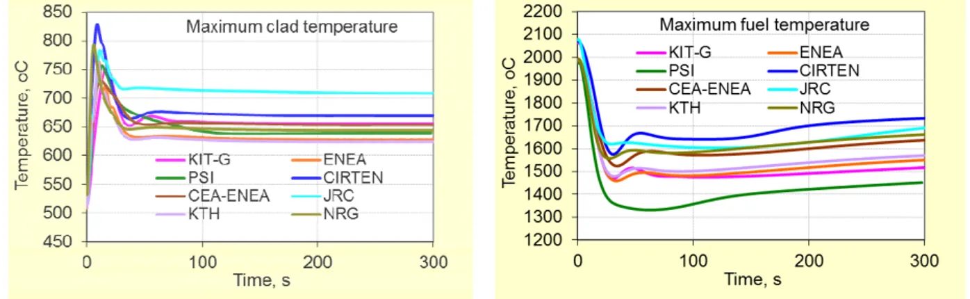
In case of a UTOP transient, for reactivity insertion of 250 pcm within 10 s (possibly due to: voiding of part of the active core region enveloping void introduction in case of SGTR, core compaction, fuel SA blockage, etc.), at BOC as well as at EOC core conditions, peak fuel pin cladding is not expected to fail, since there is a large margin to creep rupture limit. The more critical issue is the maximum fuel temperature that, because of the initial core nuclear power excursion (peak power up to ~ 230% the nominal value), is expected to exceed the MOX melting point in the initial phase of the transient. However, all codes agree that fuel melting is observed only in the centre of the peak fuel pin (pellets). Therefore, extended fuel rod damage can be excluded, as well as the likelihood for this transient to evolve towards a severe accident. In case of ULOF transient, no relevant flow undershoot is expected in the initial phase of the transient and enhanced stable natural convection, around 23% of the nominal value, establishes in the primary circuit. Furthermore, the prevalent negative reactivity feedbacks reduce the core power down to about two-third of the nominal value. As a result, the ULOF transient in the ALFRED reactor can be easily accommodated, since the maximum clad temperature remains well below the creep rupture limit in the long term (maximum clad temperature stabilizes below 700 °C). Besides, very large minimum clad failure time of ~ 1.6E+5 seconds (~ 2 days), under the minimum coolant flow conditions (initial flow undershoot) at both BOC and EOC conditions, are calculated by SIM-LFR code.
In case of ULOHS transient, the maximum clad temperature is not a critical issue, since the minimum clad failure time is > 1.E6 seconds, as calculated by SIM-LFR at both BOC and EOC conditions. Because of the uniform temperature distribution establishing in the primary circuit, the main concern is on the average vessel wall temperature, which in ~ 1 hour transient time approaches 670 – 700 °C, thus questioning the long term structural integrity of the vessel under these elevated temperature conditions. The sluggish time response to this DEC transient is ascribed to the large primary loop thermal inertia and a rather large cumulative negative reactivity effect coming from the negative fuel, diagrid, pads, Pb-coolant and CRs drivelines feedback effects, resulting in a very effective decrease of the core nuclear power towards the decay level. Sufficient grace time (>> 30 minutes) is available for the operator intervention to terminate this transient by manually shutting down the reactor and cooling down the primary circuit.
The evolution of the unprotected LOOP (ULOHS+ULOF) transient is characterized first by the loss of flow with transition to natural convection in the primary circuit, such as under ULOF, and then by the loss of heat sink with core nuclear power decrease towards the decay level, such as under ULOHS. Because of the very low natural convection flow rate which stabilizes in the primary circuit and consequent significant core ∆T increase, the maximum clad temperature is about 100 - 120 °C higher than under ULOHS. On the contrary, the very low primary flow rate limits the significant vessel wall temperature increase predicted under ULOHS, and thus the long term structural integrity of the vessel is guaranteed. According to the SIM-LFR results, the minimum clad failure time is of ~ 2.1E+4 seconds at both BOC and EOC conditions.
Therefore, also under this very unlikely DEC transient, sufficient grace time (>> 30 minutes) is available for the operator intervention to terminate this transient by manually shutting down the reactor and cooling down the primary circuit.
All codes agree that the ALFRED reactor is not expected to experience any fuel pin failure during SA flow area blockages less than 75% even in case of unprotected transient. For SA flow area blockages above 75%, clad failure (creep rupture) has to expected. Clad melting point seems reached for flow area blockages above 95%, while fuel melting temperature is reached only for flow area blockages above 97.5%. The SIMMER-III results for a protected case also suggest that nearly total blockages could be well accommodated if the reactor is shutdown within 5 seconds from their detection (i.e. 10 seconds from the initiation of the accident). However, for ALFRED sudden and complete flow blockage is prevented by the SA design solution consisting in multiple inlet openings. Any other blockage caused by deposition of material will be likely gradual and can be monitored by detection of an increase of coolant outlet temperature of each SA.
The analysis of the “practically excluded” event of SCS failure with total unavailability of DHR system has highlighted a slow temperature increase of the primary system, thanks to its large thermal inertia and good coolant mixing throughout the primary pool. This transient presents no imminent safety issue to the ALFRED reactor in the first several hours. However, all primary cooling circuit temperatures, in a longer time horizon, will start increasing slowly at a rate of about 30 °C per hour and will reach ~500 °C in 3 hours. However, the operator has sufficient time for manual intervention by re-activating SCS or sub-systems of the DHR-1 system, in order to prevent overheating of the whole primary system, including the reactor vessel.
The protected loss of flow transients with simultaneous malfunction of the feedwater temperature or flow rate control system on the secondary side have no safety concern in the short term, since the perturbation on core temperatures is not significant. In all code calculations, the initial clad temperature peak produced by the loss of forced circulation in the primary circuit is below 650 °C. Furthermore, there is no risk of lead freezing at the MHX outlet, just after the DHR-1 system start-up. The major concern is on the risk of lead freezing in the medium term, since the power removal by the DHR-1 system exceeds the decay power. The Pb freezing is expected within about 2 – 4 hours, depending on the different conditions of coolant mixing calculated by the codes in the primary pool surrounding the MHX. In fact, the lack of mixing in this wide region, such as predicted by RELAP5 code, reduces significantly the effective thermal inertia of the primary system and then the elapsed time to Pb freezing. However, during this time period the operator has sufficient time to deactivate sub-systems of the DHR-1 system, in order to prevent Pb-coolant freezing at the outlet of the MHX. Future DHR design improvements are foreseen to control in a passive way the DHR-1 and DHR-2 power removal, and thus avoiding the need of operator actions in the medium and long term. Regarding the SGTR accident, it was observed that, the steam generated by one bayonet tube rupture accident flows upward in the damaged SG and reaches the cover gas passing through the gas vents. However, as a consequence of the large amount of steam produced in the case of seven broken tubes (2.5-3.5 kg/s), traces of steam are expected to flow from the damaged SG directly and indirectly to the core. The small amount of steam enters the core downcomer mostly by the inner path, as shown by the void fraction calculated in the cells beneath the core.
However, the very low amount of vapor entering the core, the limited vapor residence time and the negative coolant expansion reactivity effect in the optimized ALFRED reactor core do not result into a positive reactivity insertion and thus represent no safety concern. Besides, in the SIMMER-III simulation, all the water injected into the Pb-coolant instantaneously fully vaporizes in contact with it at the injector tube exit region. Moreover the cover gas space, due to SIMMER-III 2D model limitation, has been modeled with separated volumes communicating only with small gas openings in the higher part, that are partially obstructed due to lead sloshing resulting in steam flowing through no realistic flow paths (e. g. downward in the pump ducts of the faulted SG). In reality, only a fraction of the injected water will be vaporized instantaneously when contacting lead and the remaining liquid water will be encapsulated in vapor bubbles and transported to the cover gas region formed by only one large volume, hence lead and steam can flow freely into the gas space. This should be kept in mind when analyzing SGTR accident simulation results.
KALLA experimental tests and Russian tests also indicated the difficulty for the vapour bubbles, generated during the lead-water interaction, to reach the core inlet section because of the drag effects produced by the liquid metal flow in the downcomer region of the reactor. A dedicated scaled facility should be foreseen to analyse in depth the SGTR phenomena further as part of the future R&D activities for LFR.
In general, the consistency of various code results for the same transient was rather good. For all DEC events the codes predicted similar transient behaviour and then similar conclusions can be drawn. Some of the observed discrepancies might be correlated to the different schematization detail of the primary and secondary circuits, or correlated to the fuel rod gap behaviour in transient conditions, due to the lack of a dedicated fuel rod gap dynamic model in some of the codes.
Finally, the analysis of the DEC transients performed for the Pb-cooled ALFRED design have demonstrated the very forgiving nature of this plant design when compared to other similar plant design, ascribable to the combination of:
• the inherently, large thermal inertia of the Pb-cooled primary system,
• the detailed focus on the optimization of all safety relevant system, in particular emphasizing appropriate design of all relevant control and safety system (as well as components), and
• optimizing the neutronic core characteristics of the ALFRED “core system” thereby assuring various reactivity feedback effects (fuel, diagrid, pads, Pb-coolant and CRs drivelines expansion reactivity) that effectively depress the reactor power under all adverse DEC transient conditions,
• as the ALFRED core is specifically designed to accommodate the ULOF transient. This work was performed within the LEADER Project (Contract No. FP7-249668) under the auspices of the EU 7th Framework Program.
CONTENTS
1. INTRODUCTION ………..….. 10
2. ANALYSED TRANSIENTS AND COMPUTER CODES USED ………..….. 12
2.1 DEC transients ………. 12
2.2 Computer codes …………...………. 14
3. ETDR (ALFRED) DESIGN ……….……….... 15
3.1 Primary system ……….……….. 16
3.2 Steam generator ……….……….. 19
3.3 Primary pump ……….. 23
3.4 Reactor core ………. 24
3.4.1 BOC and EOC cores: layout and main characteristics ………... 28
3.4.2 Nuclear kinetic data and reactivity coefficients ………..……… 31
3.5 Secondary circuits ……….... 33
3.6 Decay heat removal system ………...……….. 34
3.6.1 System actuation and operation ……….. 37
3.6.2 DHR actuation logic ……….………… 39
4 BENCHMARK OF CODES ……….………...……. 41
4.1 ULOF transient ………. 41
4.2 UTOP transient ………. 44
4.3 ULOHS transient ……….. 48
4.4 Conclusions from code benchmark ……….. 51
5 DEC TRANSIENT RESULTS ……….…… 52
5.1 TR-4: Unprotected reactivity insertion (UTOP) ……….…….… 52
5.1.1 TR-4 transient: SIM-LFR results (KIT-G) ……….. 52
5.1.2 TR-4 transient: TRACE/FRED results (PSI) ……….. 55
5.1.3 TR-4 transient: TRACE results (JRC-IET) ………. 56
5.1.4 TR-4 transient: RELAP5 results (ENEA) ………...…… 58
5.1.5 TR-4 transient: CATHARE results (ENEA/CEA) ……….. 59
5.1.6 TR-4 transient: SPECTRA results (NRG) ………... 60
5.2 T-DEC1: Unprotected loss of flow (ULOF) ………...…… 63
5.2.1 T-DEC1 transient: SIM-LFR results (KIT-G) ……….……… 63
5.2.2 T-DEC1 transient: TRACE/FRED results (PSI) ……….……… 66
5.2.3 T-DEC1 transient: TRACE results (JRC-IET) ……….….. 68
5.2.4 T-DEC1 transient: RELAP5 results (ENEA) ……….…. 70
5.2.5 T-DEC1 transient: CATHARE results (ENEA/CEA) ……….…… 72
5.2.6 T-DEC1 transient: SPECTRA results (NRG) ……….…. 73
5.2.7 T-DEC1 transient: RELAP5 results (KTH) …………..………... 76
5.2.8 T-DEC1 transient: RELAP5 results (CIRTEN) ……….…. 77
5.3 T-DEC3: Unprotected loss of heat sink (ULOHS) ……….….. 79
5.3.2 T-DEC3 transient: TRACE/FRED results (PSI) ……….…. 83
5.3.3 T-DEC3 transient: RELAP5 results (ENEA) ……….. 84
5.3.4 T-DEC3 transient: CATHARE results (ENEA/CEA) ……….… 85
5.3.5 T-DEC3 transient: SPECTRA results (NRG) ………....….. 86
5.4 T-DEC4: Unprotected loss of offsite power (ULOHS+ULOF) ………... 89
5.4.1 T-DEC4 transient: SIM-LFR results (KIT-G) ……….…… 89
5.4.2 T-DEC4 transient: RELAP5 results (ENEA) ……….……. 92
5.4.3 T-DEC4 transient: CATHARE results (ENEA/CEA) …………...……. 93
5.4.4 T-DEC4 transient: SPECTRA results (NRG) ……….….… 94
5.4.5 T-DEC4 transient: RELAP5 results (KTH) ………... 96
5.5 T-DEC5: Unprotected partial blockage in the hottest fuel assembly ………..…. 97
5.5.1 T-DEC5 transient: SIM-LFR results (KIT-G) ………. 98
5.5.2 T-DEC5 transient: RELAP5 results (ENEA) ……….. 103
5.5.3 T-DEC5 transient: SPECTRA results (NRG) ………. 103
5.5.4 T-DEC5 transient: SIMMER results (JRC-IET) ………. 105
5.6 T-DEC6: Failure of secondary cooling circuits …....………..……. 109
5.6.1 T-DEC6 transient: SIM-LFR results (KIT-G) ………. 109
5.6.2 T-DEC6 transient: RELAP5 results (ENEA) ……….. 113
5.6.3 T-DEC6 transient: SPECTRA results (NRG) ……….. 115
5.7 TO-3: Reduction of FW temperature with all primary pumps trip ..………..….. 118
5.7.1 TO-3 transient: SIM-LFR results (KIT-G) ……….…. 118
5.7.2 TO-3 transient: RELAP5 results (ENEA) ……….….. 122
5.7.3 TO-3 transient: SPECTRA results (NRG) ……….…. 124
5.8 TO-6: Increase of FW flowrate with all primary pumps trip …………...…. 126
5.8.1 TO-6 transient: SIM-LFR results (KIT-G) ……….……. 127
5.8.2 TO-6 transient: RELAP5 results (ENEA) ……….….. 130
5.8.3 TO-6 transient: SPECTRA results (NRG) ………..…. 132
5.9 Steam generator tube rupture (SGTR) event (CIRTEN) ………..………...…. 135
5.10 CFD simulation of bubble transport in SGTR/SGTL event (KTH) ……..……... 141
6. CONCLUSIONS ……… 146
REFERENCES ……….……….. 149
APPENDIX A. Description of computer codes used ………. 150
A.1 SIM-LFR code used by KIT-G ………..………...………… 151
A.2 TRACE/FRED code used by PSI ………..………...……… 153
A.3 TRACE code used by JRC-IET ………..………...………...…… 154
A.4 RELAP5/MO3.3 code used by ENEA, KTH and CIRTEN ………...…… 156
A.5 CATHARE V2.5_2 code used by ENEA / CEA ………...……… 158
A.6 SPECTRA code used by NRG ………..………….…………..…… 159
A.7 SIMMER-III code used by CIRTEN ……...………..………...…… 161
A.8 SIMMER-III code used by JRC-IET ...………..………...…… 164
APPENDIX B. KIT-G contribution to Deliverable DEL022 ……….………...……. 165
APPENDIX D. JRC-IET contribution to Deliverable DEL022 ………. 217
APPENDIX E. NRG contribution to Deliverable DEL022 ……….…………..…... 239
APPENDIX F. KTH contribution to Deliverable DEL022 ……….…….………….. 291
1.
INTRODUCTION
This report is prepared to satisfy the requirements of Deliverable DEL022 of the WP5.5 in the EU 7th Framework Program’s Research Project “Lead-cooled European Advanced Demonstrator Reactor (LEADER)”. The main objective of Deliverable DEL022 is to report on the results of the analysis of DEC transients for the ETDR (ALFRED) reactor.
ALFRED is a pool-type, Pb-cooled fast reactor of 300 MWth power. The reactor core consists of 171 fuel assemblies (57 inner core fuel assemblies and 114 outer core fuel assemblies fuelled with MOX) and 16 control/safety assemblies. The primary coolant working temperature is in the range 400–480 °C. The core power is removed by 8 steam generators (SGs), installed in an annular zone near the top of the reactor vessel, and connected with 8 secondary circuits which are fed with water at 335 °C and 188 bar. Super-heated steam at 450 °C and 180 bar pressure from the SG outlet feeds the turbine to produce a net electrical power of about 125 MWe. The Decay Heat Removal system (DHR) of ALFRED is constituted of two independent and redundant systems: 1) DHR-1: 4 Isolation Condenser systems (ICs) connected to 4 Steam Generators (SGs); 2) DHR-2: 4 Isolation Condenser systems (ICs) connected to the remaining 4 Steam Generators (SGs).
The safety analysis is deterministic and the methodology is similar to that employed in the LWR safety analysis, i.e. calculate the consequences for certain postulated events that could occur in the Pb-cooled ETDR (ALFRED) reactor. The analysis presented in this report is for the design extension condition (DEC) events. The postulated DEC events are very unlikely events that foresee possible multiple failures or the failure of safety or mitigating systems, such as the reactor scram in the so-called unprotected transients. One of the major objectives of this study is to evaluate the impact of core and plant design features on the intrinsic safety behavior of the plant. Furthermore, the grace time available before critical core and vessel wall temperatures are reached, or risk of lead freezing is attained in the primary system are investigated.
For ALFRED a total of 8 transients were selected as representative of all identified DEC transients reflecting a wide range of potential transient initiators. These transients include several unprotected transients such as the ones connected with the loss of flow in the primary system and/or the loss of heat removal by the secondary system, and the overpower transient following reactivity insertion. The overcooling transients are investigated in connection with the loss of flow in the primary circuit, which are then most penalizing as related to the risk of lead freezing at the SG outlet. Furthermore, the consequences of the unlike event of the concomitant break of both SG tube walls (Steam Generator Tube Rupture - SGTR) related to: 1) potential mechanical loads on the primary system structures due to water-Pb interaction and 2) core voiding effect due to eventual steam bubble transport through the core are investigated. Different system codes adapted to deal with Pb coolant have been used for the DEC transient analysis by the partners involved in the WP5 activities of the LEADER project. These include (see Appendix A):
• the RELAP5/MOD3.3 system code (modified by ENEA/Ansaldo/Uni-Pisa and used by ENEA, KTH and CIRTEN),
• the SIM-LFR system code (developed by KIT),
• the TRACE/FRED system code (coupled and adapted by PSI),
• the TRACE system code (adapted by JRC-IET),
• the SIMMER-III code (used by CIRTEN and JRC-IET),
• the CATHARE V2.5_2 system code (developed by CEA),
• the SPECTRA system code (developed by NRG), This report is organized as follows:
Section 2 first provide a table of the DEC (unprotected and protected) transients that were selected for the safety analysis described in this report. Section 3 provides a short overview of the ALFRED design and main parameters that play an important role during postulated DEC transients (detailed information is provided in DEL015 along with the results of steady-state operation at full power). Section 4 presents the results of the code benchmark on several representative unprotected transients (UTOP, ULOF and ULOHS), performed with the aim to verify the consistency of code results. Section 5 present the results of the analyses for each DEC transient as obtained by the various partners employing their codes. As indicated in section 5, not all the transients have been analyzed by all the partners, but at least three partners have analyzed the same transient, thus providing the possibility to compare and better judge the consistency of code results. The conclusions obtained during this study are described in Section 6.
This report responds to the Deliverable D022 and is a joint report to which all Task 5.5 partners have contributed. Thus, the report consists of a compilation of information, made available by different colleagues from various organizations, extracted from the following reports, which are also being published in their full length as appendixes to the LEADER Deliverable DEL022. Direct use of the appropriate parts of these reports has been made for the main part of the Deliverable DEL022.
2.
ANALYSED TRANSIENTS AND COMPUTER CODES USED
The representative accident initiators for both Design Basis Conditions (DBC) and Design Extension Conditions (DEC) have been defined in Deliverable DEL011-2012. On the basis of the design solution adopted for the ETDR (ALFRED), a simplified line-of-defense strategy was applied for identification of accident initiators. Furthermore, the identified event initiators were categorized and the most representative for each category were selected for safety analysis to be carried out in tasks 5.4 and 5.5 of the LEADER project.
2.1 DEC transients
The list of DEC transients analyzed by various research organizations using different system codes is reported in Table 2-1. These events of very low frequency are characterized either by the failure of reactor scram (so-called unprotected accidents) involving:
• TR-4: Unprotected reactivity insertion transient (UTOP),
• T-DEC1: Unprotected loss of flow transient (ULOF),
• T-DEC3: Unprotected loss of heat sink transient (ULOHS),
• T-DEC4 (LOOP): Unprotected loss of offsite power transient (ULOF+ULOHS),
• T-DEC5: Unprotected partial SA blockage,
or by the simultaneous occurrence of multiple failures in some protected transients:
• T-DEC6: Loss of all secondary circuits with total unavailability of DHR system,
• TO-3: Loss of all primary pumps with reduction of feedwater temperature,
• TO-6: Loss of all primary pumps with increase of feedwater flowrate by 20%.
The unprotected transients (TR-4, T-DEC1, T-DEC3, T-DEC4 and T-DEC5) are mainly investigated to obtain insights on the intrinsic safety behavior of ALFRED and thus verifying the adequacy of the solutions adopted for the core and the plant design.
The analysis of the extremely unlikely T-DEC6 event characterized by the failure of all secondary circuits with total unavailability of any DHR system, leading to a progressive increase of the primary temperatures, is investigate to determine the grace time left to the operator before reaching limiting temperatures for the core and the vessel structures.
The protected transients TO-3 and TO-6 are mainly investigated to assess an important aspect for LFR systems related to the risk of lead freezing in the primary cooling circuit. This specifically concerns situations after reactor shutdown and activation of the DHR system, since, in the medium term, heat removed by the DHR system (which is almost constant in time) is expected to exceed the decreasing decay heat. In this case the lead freezing might become an issue and then the grace time left to the operator to undertake appropriate corrective actions must be evaluated.
In addition to the transient list in Table 2-1, the steam generator tube rupture (SGTR) event has been analyzed within DEC, despite of the very low frequency expected for this event through the adoption of double-wall steam generator tubes, along with the possibility to detect single tube wall break by the continuous monitoring the gas pressure inside the gap. The SGTR transient has been analyzed by CIRTEN using the SIMMER-III code postulating the concomitant break of both walls.
Table 2-1: DEC transients analyzed for the Pb-cooled ETDR (ALFRED)
Case
Number Transient Description
ENEA KIT-G NRG JRC-IET KTH PSI ENEA / CEA CIRTEN
RELAP5 SIM-LFR SPECTRA SIMMER / TRACE RELAP5 / CFD TRACE/ FRED CATHARE RELAP5 / SIMMER (*) TR-4 Reactivity insertion (enveloping SGTR, flow blockage, core compaction)
Reactivity insertion (voiding of part of active region
enveloping voids introduction due SGTR,
core compaction, fuel blockage) = 250 pcm Reactor at hot full power
(HFP) X X X X X X X (**) X X TO-3 Reduction of FW temperature + all pumps stop
Loss of one preheater (feedwater temperature reduction from 335oC down
to 300oC) All primary pumps are
stopped Reactor is tripped X X X X X TO-6 Increase of FW flowrate+ all pumps stop 20 % increase in feedwater flowrate All primary pumps are
stopped Reactor is tripped X X X X X T-DEC1 Complete loss of forced flow + Reactor trip fails (total ULOF)
All primary pumps are stopped Feedwater system available
Reactor trip fails
X X X X X X X X X X
T-DEC3
Loss of SCS+ Reactor trip fails (ULOHS)
All primary pumps are operating DHR system is operating
Reactor trip fails
X X X X X X X T-DEC4 Loss of off-site power (LOOP) + Reactor trip fails (ULOHS + ULOF)
All primary pumps are stopped SCS is lost DHR system is operating
Reactor trip fails
X X X X X X X
T-DEC5
Partial blockage in the hottest fuel assembly
Reactor trip fails The maximum acceptable flow reduction factor has to
be determined
X X X X X X X
T-DEC6 SCS failure
All primary pumps are operating DHR system totally fails
Reactor is tripped
X X X X X
Note (*) SIMMER-III code has been used by CIRTEN for the analysis of SGTR transient (DEC event not included in this list)
Note (**) KTH plans to look at core voiding due to leak from steam generator by CDF analysis
(simulation of bubble transport to the core in Lagrangian framework by turbulent coolant voiding taking into account uncertainties in: bubble size distribution, different correlations for bubble drag in lead, locations of possible leakage from SG, leak rate, etc.) Note (***) Only KIT-G with SIM-LFR code for all DEC transients and JRC-IET for T-DEC5 transient
DEC Transients
Transients to be analyzed for Pb-cooled ALFRED Design (LEADER project)
Burnup State
Transients analyzed for Pb-cooled ALFRED Design
B O C ( ** *) E O C
In general, all DEC transients have been analyzed starting with the reactor in steady-state conditions at full power (300 MWth) from the end of cycle (EOC) condition, which seems more conservative with respect to the beginning of cycle (BOC) condition, from the safety point of view. Only KIT with SIM-LFR code has investigated all DEC transients starting from both BOC and EOC conditions. Their analyses confirm that the general situation at BOC condition does not differ significantly from EOC condition, and thus similar conclusions apply in both cases.
2.2 Computer codes
For the DEC transient analysis different computers codes are used by various organizations. In general, already validated computer codes developed for safety analysis of nuclear power reactor using different coolants have been modified by introducing a consistent set of physical and thermodynamic properties and empirical correlations for Pb in the modules devoted to evaluating heat and mass transport phenomena.
The validation phase of these codes for LFR reactor applications is in progress on the basis of the available experimental database.
The issues associated with each of the different system codes used are discussed in more detail in Appendix A.
3.
ETDR (ALFRED) DESIGN
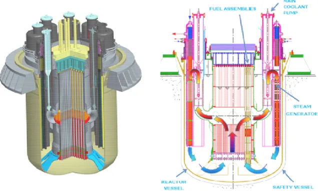
The ETDR (ALFRED) configuration is illustrated in Fig. 3-1 [1].
Fig. 3-1: ALFRED configuration (3D view on the left and 2D vertical section on the right) Main features of the ALFRED design are:
• Pool type configuration characterized by a reactor vessel and the cavity liner safety vessel,
• Hexagonal wrapped fuel assemblies extended to cover gas to simplify fuel handling (FAs weighted down by tungsten ballast for refueling and kept in position by upper grid springs during operation),
• Mechanical pumps located in the hot collector,
• Double-walled straight SG tubes with continuous monitoring of tube leakages.
The thermal cycle is completely consistent with the ELFR thermal cycle: primary lead temperature being between 400-480°C, secondary side pressure 180 bars, once through SGs with water/steam temperature range from 335 to 450°C in superheated conditions, the overall efficiency has been evaluated higher than 42%. ALFRED will also allow for testing the connection to the electrical grid, with a generated power of about 125 MWe.
Safety of ALFRED is extensively based on the use of the defense in depth criteria, enhanced by the use of passive safety systems (actively actuated through locally stored energy source, always available, and fully passively operated). Safety features of the LFR system have been designed since the beginning of the activities to face challenging conditions and events, thanks to the very forgiving and benign characteristics of the coolant. As an example, there is no need of off-site or emergency AC electrical power supply to manage the design basis accident
Centro Ricerche Bologna UTFISSM–P9SZ-007 0 L 16 402
conditions; the only action needed is the addition of water to maintain the level in the decay heat removal (DHR) pools which are already sized to guarantee at least three days of unassisted fully passive operation and can be easily re-filled in the following days.
The reference design configuration for the plant safety analysis, presented in details in Ref. [2], is summarized in the following sub-sections. Besides, in the DEL015-2013 devoted to DBC transient analysis, the results of the steady-state calculations for ALFRED at nominal power with different codes are also reported, along with a code benchmark.
3.1 Primary system
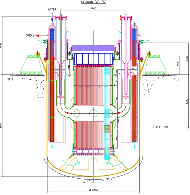
Fig. 3.1-1 and Fig. 3.1-2 present the general layout of the primary system. The main ETDR (ALFRED) parameters are listed in Table 3.1-1 [11].
Fig. 3.1-2: Reactor block configuration – top view [4]
Table 3.1-1: ETDR (ALFRED) main parameters [11]
ALFRED Main Parameters
Power 300 MWth
Thermal efficiency > 40%
Primary system Pool, compact
Primary circulation 8 mechanical pumps Primary pressure loss 1.5 bar Primary thermal cycle 400 – 480 °C
Fuel MOX
Fuel cladding 15-15/Ti + coating Fuel clad max temperature 550 °C
Main & safety vessel Austenitic SS Steam generators 8 - integrated
Secondary cycle 180 bar, 335 – 450 °C
Internals Removable
Seismic design 2D isolators
Reactor inner vessel
ALFRED inner vessel (Fig. 3.1-3) is made of 3 sub-assemblies as schematized in Fig. 3.1-4:
• The cylindrical vessel [6],
• The core lower grid [7],
• The core upper grid [8].
The inner vessel (see Fig. 3.1-3) is a double wall shell: the outer thick wall has a structural function, while the inner thin wall follows the core section profile. Lead flow is guided from the FAs outlet towards the primary pump (PP) inlet pipes by a toroidal half-ring The inner vessel is fixed to the cover by bolts and is radially restrained at the bottom.
Fig. 3.1-3: 3D view of the cylindrical inner vessel [3]
Upper grid Cylinder Lower grid Pin Upper grid Cylinder Lower grid Pin
Fig. 3.1-4: ALFRED inner vessel assembly schematics [3]
Inner Vessel assembly Inner Vessel
Core lower grid has a box structure with two horizontal perforated plates connected by vertical plates. Plates holes are the housing of FAs foots. The plates distance must be sufficient to assure the verticality of FAs. Core upper grid has a box structure similar to the core lower grid but more stiff. It has the function to push down the FAs during the reactor operation. A series of preloaded disk springs presses each FA on its lower housing.
Reactor outer vessel
The reactor outer vessel [9] is a cylindrical vessel with a torospherical bottom head. It is anchored to the reactor pit from the top. Reactor outer vessel is closed by a roof that supports the core and all the primary components. Its upper part is divided in two branches by a “Y” junction: the conical skirt that supports the whole weight and the cylindrical that supports the Reactor Cover. A cone frustum welded to the bottom head has the function of bottom radial restraint of the Inner Vessel.
Inner Vessel radial support
Support flange Cover flange
Inner Vessel radial support Support flange Cover flange
Fig. 3.1-5: ALFRED reactor outer vessel schematics [9]
3.2
Steam generator
Steam Generators (SG) [10] (called also MHX in this transient analysis) are distributed around the Inner Vessel. It is a bayonet tubes Steam Generator made by 4 tubes bayonets with an intermediate medium between lead and water/steam. This solution mitigates the SGTR effects: the intermediate medium allows an instantaneous identifying of a tube rupture event. An independent cooling loop made by a series of U-tubes avoids the heating of Reactor Vessel removing the heat dispersions from the hot zone. The main SG operation parameters are listed in Table 3.2-1.
Vertical
view
Vertical
section
Horizontal
section
Vertical
view
Vertical
section
Horizontal
section
Fig. 3.2-1: ALFRED steam generator schematics [10]
Table 3.2-1: Main SG operation parameters [12]
Main SG Parameters
Nominal reactor core power 300 MWth Number of steam generators 8
Number of primary pumps 8
Power removed by 1 SG 37.5 MWth Lead (Primary system)
SG outlet T (Core inlet T) 400 °C SG inlet T (Core outlet T) 480 °C
Mass flow rate (1 SG) 3247.5 kg/s Water/Steam (Secondary system)
Pressure 180 bar
Water inlet T 335 °C
Steam outlet T 450 °C
Mass flow rate 24.1 kg/s
The height difference between the core mid-plane and SG mid-plane is about 1.87 m (see Fig. 3.2-2). The main SG design data are given in Table 3.2-2, while the main SG tube geometric data and design are schematized in Fig. 3.2-3 [12].
Table 3.2-2: Main SG design data [12]
Steam Generator Geometry Bayonet tube
Number of coaxial tubes 4
Slave tube O.D 9.52 mm
Slave tube thickness 1.07 mm
Inner tube O.D 19.05 mm
Inner tube thickness 1.88 mm
Outer tube O.D 25.4 mm
Outer tube thickness 1.88 mm
Outermost tube (Gap) O.D 31.73 mm Outermost tube thickness 2.11 mm
Length of exchange 6 m
Argon Plenum Height 1 m
Helium Plenum Height 0.8 m
Steam Plenum Height 0.8 m
Fig. 3.2-3: Main SG bayonet tube geometric data and design [11]
Bayonet tube specifics [12]: 4 tubes
3 tube sheets
Insulation between the inner tubes used to avoid steam formation during the water descent down the inner tube. Synthetic diamonds (for excellent heat transfer) and helium (for continuous water leakage monitoring) filling the gap between the two outer tubes.
Steam Generator Bayonet Tube Concept
• Bayonet vertical tube with external safety tube and internal insulating layer
• The internal insulating layer (delimited by the Slave tube) has been introduced to ensure the production of superheated dry steam. Without an insulating system the high ∆T (≈115°C) between the rising steam and the descending feedwater promotes steam condensation in the upper part of the steam generator.
Sensitivity on materials and extension of this layer has been performed and the results will be discussed later.
• The gap between the outermost and the outer bayonet tube is filled with pressurized helium and high thermal conductivities particles to enhance the heat exchange capability.
In case of an external tube break this arrangement guarantees that primary lead does not interact with the secondary water. Moreover a tube break can be easily detected monitoring the Helium gap pressure.
3.3
Primary pump
The Primary Pump (PP) is located in the hot side of a SG. It is surrounded by the SG tube bundle and its housing is the SG casing. The Pump is fixed to the top of SG casing by a bolted joint. This allows an easy removal of the component.
The Primary Pump studies are in progress. Based on analyses performed during previous LFR projects (EUROTRANS, ELSY) an axial pump has been adopted.
The PP impeller material is an issue. The stainless steel (SS) cannot be used because the high speed achieved at the top of the impeller blades induces a very fast material corrosion. Maxthal ceramic material has been proposed. Test campaigns must be performed still to select the proper PP impeller material.
The primary pump outline, the SG and PP schematics, as well as the Inner Vessel, PP and SG coupling schematic are illustrated in Fig. 3.3-1 [3].
Water Hot Lead Cold Lead Steam Water Hot Lead Cold Lead Steam a) b) c)
Fig. 3.3-1: a) Primary pump outline; b) SG and PP coupling schematics; c) Inner Vessel, Primary Pump and Steam Generator coupling schematics [3]
3.5
Reactor core
In the framework of the LEADER project [13], the ALFRED core is devoted to the demonstration of a fast reactor cooled by lead.
The considered fuel is MOX (conventional MOX): the Pu vector is estimation from the reprocessing of PWR spent UO2 fuel burnt up to 45 GWd t-1; with a 4.5% initial enrichment in 235
U and 15 years of cooling period. The assumed ratio of 241Am/Pu is 1.3%. The specifications for the assumed isotopic composition and densities for the MOX fuel, the Pb coolant, the structural materials and the B4C can be found in [14].
Table 3.4-1: ALFRED core parameters
Parameter Unit Value
Pellet radius mm 4.5
Gap thickness mm 0.15
Clad thickness mm 0.6
Pin diameter mm 10.5
Wrapper thickness mm 4.0
Distance between 2 wrappers mm 5.0
Lattice pitch (hexagonal) mm 13.86
Pins per FA - 127
Inner vessel radius cm 165
Inner / Outer FAs number - 57 / 114
Inner / Outer enrichment
(Pu+241Am) / (Pu+241Am+U) atom% 21.7% / 27.8%
Mass inventory of actinides: BOC - U / Pu / Minor Actinides EOC - U / Pu / Minor Actinides
tons 5.27 / 1.78 / 0.038 5.19 / 1.74 / 0.043
Fuel residence time month 60
Number of batches - 5
Cycle length month 12
∆keff swing pcm ≈ -2600
BoC/EoC keff (with CR extracted) - 1.025 / 0.999
Assumed grace time for cladding failure (in ULOF conditions) minutes 30
Table 3.4-2: Fuel pin geometric parameters [5, 15]
Description Length
Bottom plug [mm] 50
Gas plenum [mm] 550
Bottom insulator ZrO2-Y2O3 [mm] 10
Active length [mm] 600
Upper insulator ZrO2-Y2O3 [mm] 10
Spring [mm] 120
Upper plug [mm] 50
Fig. 3.4-1 presents the proposed ALFRED core configuration made of 171 Fuel Assemblies, 12 Control Rods and 4 Safety Rods, surrounded by 108 Dummy Elements (ZrO2-Y2O3) shielding
the Inner Vessel.
The Fuel Assembly and Fuel Pin drawing are reported in Ref. [5]. Fig. 3.4-2 to Fig. 3.4-4 present the fuel sub-assembly design, while Fig. 3.4-5 presents the fuel pin design for this ALFRED core configuration.
The preliminary (until final design calculations will become available) foreseen core pressure drop is ~1.0 bar, that is approximately two-third of the total primary circuit pressure drop (~1.5 bar).
Fig. 3.4-1: ALFRED core configuration.
Inner zone (57 violet FA) and outer zone (114 blue FA) [15].
Ballast Preloaded Spring
Lead Free Level (during refueling)
Top Grid
Diagrid
The Basic Concept
FAs During refueling, the FA sinks due to its own
weight. A dedicated subsystem (the Ballast), set above the lead free level, is needed to increase the FA weight.
During operation, preloaded springs, supported by a Top Grid, provide the additional vertical force to win the drag. A "normal" FA would float in the lead
and a specific design is required to avoid it:
2 7 7 0 1 0 6 0 1 3 7 0 7 9 0 0 127 Pins
FA, basic geometry
6
0
0
Mixing zone level
Lead free level (refueling) 2 7 7 0 1 0 6 0 1 3 7 0 7 9 0 0 127 Pins
FA, basic geometry
6
0
0
Mixing zone level
Lead free level (refueling)
Fig. 3.4-3: Fuel sub-assembly (FA) design for ALFRED core configuration [5, 16]
Spike Core Funnel Ballast Ballast Funnel Core Spike e m p ty s e c ti o n s Spike Core Funnel Ballast Ballast Funnel Core Spike e m p ty s e c ti o n s
1430 (overall length) 600 (60 pellets) 550 10 10 10 120 FA, Pin 50 20 1330 (cladding) 50 18.4 0.8 0.8 1430 (overall length) 600 (60 pellets) 550 10 10 10 120 FA, Pin 50 20 1330 (cladding) 50 18.4 0.8 0.8
Fig. 3.4-5: ALFRED FA pin - schematic mechanical drawings [5, 16]
3.4.1 BOC and EOC core: layouts and main characteristics
The core power distribution has been calculated by both MCNPX and ERANOS [15]. Only the results obtained by MCNPX are reported here.
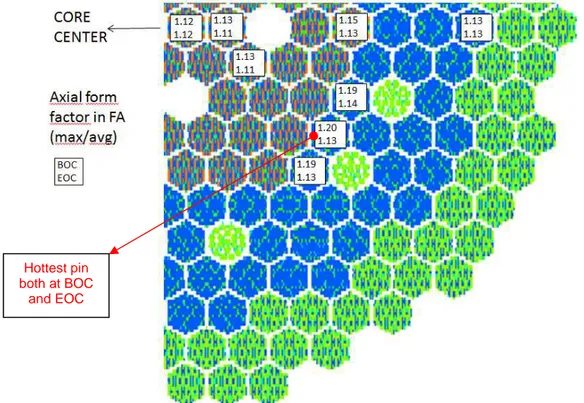
The power generation in the Fuel Assemblies is shown in Fig. 3.4.1-1 (1/4 of the core), calculated at BOC (CR inserted of 17 cm in the active zone) and at EOC (CR withdrawn).
The maximum value is at the center at BOC (2.21 MWth) and in the outer zone at EOC (2.17
MWth), but the hottest pin is not in these FAs, but in the outer zone, as depicted in Fig. 3.4.1-2.
Here also the axial form factors, as calculated in some FAs, are shown.
Fig. 3.4.1-2: Axial form factors in some FAs at BOC and at EOC
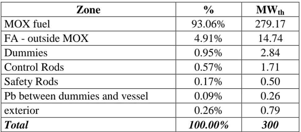
The power is deposited not only in the fuel, but also in the other materials, due to the gamma and neutron emission in the fission process. The power distribution at BOL (CR inserted of 17 cm; SR extracted), according to the materials and to the different zones is shown in Table 3.4.1-1 and Table 3.4.1-2.
Table 3.4.1-1: Power distribution according to different materials
Material % MWth MOX fuel 93.06% 279.17 Ti 15-15 0.48% 1.44 Pb 4.89% 14.66 T91 0.85% 2.55 ZrO2-Y2O3 0.32% 0.96 B4C 0.40% 1.21 Total 100.00% 300 Hottest pin both at BOC and EOC
Table 3.4.1-2: Power distribution according to different zones Zone % MWth MOX fuel 93.06% 279.17 FA - outside MOX 4.91% 14.74 Dummies 0.95% 2.84 Control Rods 0.57% 1.71 Safety Rods 0.17% 0.50
Pb between dummies and vessel 0.09% 0.26
exterior 0.26% 0.79
Total 100.00% 300
A maximum linear power value of 350 W/cm can be assumed, as deduced from Table 3.4.1-3. Table 3.4.1-3: Maximum power deposition in the hottest pin
BOC EOC
Power deposition on the FA (MWth) 2.11 2.16
Axial form factor of the FA 1.20 1.13
Pinwise form factor of
the power deposition within the FA (max pin/avg pin)
1.089
% deposition in the fuel 93.1%
Correction for more realistic batch
approximation description in MCNPX ~+4% ~+4% Estimated max linear power (W/cm) ~350 ~340
The average linear power and the axial form factors for the whole core are shown in Table 3.4.1-4.
Table 3.4.1-4: Average power deposition and axial form factors in the whole core Average FA
MWth 1.75
% deposition in the fuel 93.1%
Estimated average linear power in the
pellets (W/cm) 214
Average axial form factor of the FAs 1.16 (BOC) 1.13 (EOC) The average neutron flux in the fuel pellets is 1.54⋅1015 cm-2 s-1.
The linear power axial distribution of the average pin in the average FA and of the hottest pin are shown in Fig. 3.4.1-3.
Fig. 3.4.1-3: Linear power axial distribution
3.4.2 Nuclear kinetic data and reactivity coefficients
The kinetic characteristics of the reactor core, i.e. the effective delayed neutron fraction and the effective prompt neutron lifetime, determine the response of the core to reactivity changes due to changing plant conditions or to operator adjustments made during normal operation, as well as in abnormal transients and accidents.
The effective delayed neutron fraction at the End Of Cycle (EOC) conditions was determined to be 335 pcm [15].
Corresponding to the 8 groups of the JEFF3.1 library, the description of the effective neutron fraction and precursor life time is given in Table 3.4.2-1 at EOC.
Table 3.4.2-1: Description of the kinetic constants on the 8 groups of the JEFF3.1 library [15]
Group 1 2 3 4 5 6 7 8
β (pcm) 5,9 57,9 21,8 50,5 106,5 38,5 37,4 16,1
λ (s-1) 0,0125 0,0283 0,0425 0,1330 0,2925 0,6665 1,6348 3,5546 Global precursor disintegration constant: λ = 0,0867 s-1
Life time on the whole reactor : 6,296.10-07 s
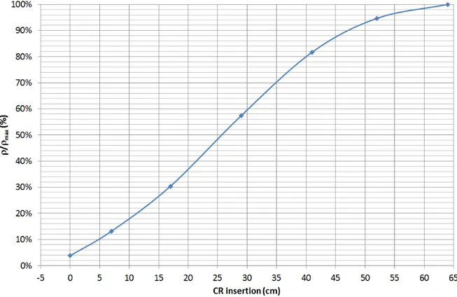
The reactivity changes with the insertion of the 12 CRs is shown in Fig. 3.4.2-1 [15]. The reactivity introduced for full CRs insertion (64 cm) at BOL, such as during automatic reactor scram, is of -8476 pcm.
Fig. 3.4.2-1: Reactivity worth of the 12 CR at different insertion lengths (core mid-plane at 30
cm; full extraction corresponds to -4 cm).
Some performances of the ALFRED core are reported in Table 3.4.2-2, as calculated by CEA with ERANOS in [16].
Table 3.4.2-2: ALFRED core characteristics and performances
Average burn-up 73,3 GWd.t-1
Max. burn-up 103 GWd.t-1
Max. DPA NRT (Fe) 85
Effective delayed neutron fraction at EOC 335 pcm* Lead void effect at EOC (fuel zones) 2 $
Doppler effect at EOC -1,7 $
* : pcm = % ∆k/k
The positive lead void effect is calculated by voiding only the fissile media. The Doppler constant has been evaluated between the nominal fuel temperature (~1500 K) and an hottest one, near the melting point (~2500 K).
The evaluation of the reactivity feedbacks during the fifth equilibrium cycle is presented in Table 3.4.2-3. It is important to notice that all these coefficients are calculated at a fixed temperature. Thus, it would not be discerning to apply these ones to the calculation of transients on the core in a very different situation: beginning of fusion of the core for example.
Table 3.4.2-3: Reactivity feedbacks Driving
temperature BOC EOC
Effective delayed neutron fraction (pcm) - 336 335
Control and Safety rods differential expansion (pcm/K) – prompt response
Coolant Temp at
core outlet -0,455 -0,218 Control and Safety rods differential expansion
(pcm/K) – delayed response
Cold-to-hot leg
by-pass Temp* -0,897 -0,429 Lead expansion coefficient (pcm/K)** Average coolant
Temp in core -0,271 -0,268 Axial clad expansion (pcm/K) Average coolant
Temp in core 0,037 0,039 Axial wrapper tube expansion (pcm/K) Clad Temp 0,022 0,023
Radial clad expansion (pcm/K) Average coolant
Temp in core 0,008 0,011 Radial wrapper tube expansion (pcm/K) Clad Temp 0,002 0,003
Diagrid expansion (Toutlet > Tc) *** Coolant Temp at
core inlet
-0,147 -0,152 Diagrid expansion (Toutlet < Tc) *** -0,519 -0,430
Pad expansion (Toutlet > Tc) *** Coolant Temp at
core outlet
-0,415 -0,430
Pad expansion (Toutlet < Tc) *** 0 0
Axial fuel expansion: free (pcm/K) Fuel Temp -0,148 -0,155 Axial fuel expansion: linked (pcm/K) Clad Temp -0,232 -0,242
Doppler constant (pcm) Fuel Temp -555 -566
Iron part of the Doppler constant (pcm) Clad Temp -74 -66 Fissile part of the Doppler constant (pcm) Fuel Temp -481 -500
*: the region here referred to is the one within the Inner Vessel, above the mixing chamber at core outlet, fed by a by-pass flow entering from the cold flow outside the Inner Vessel
**: calculated on the whole height of the fissile sub-assemblies (the other feedbacks are calculated only in the fissile zone)
***: the critical temperature for pads to enter in contact is Tc = 480 + 0.6552 * ( Tinlet – 400 ) [°C]. Concerning the control rods differential expansion effect, for the calculation it is assumed:
- At BOC: CR inserted by 16 cm into the active region; SR extracted. - At EOC: CR extracted (4 cm below the active region); SR extracted.
3.5
Secondary circuits
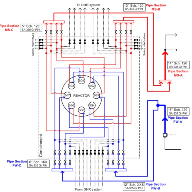
The layout of the ALFRED secondary circuits with Main Steam and Feed Water lines in the proximity of the reactor vessel in schematized in Fig. 3.5-1. The secondary system is constituted by 8 independent circuits connected to the 8 SGs. Both Feed Water and Main Steam lines are provided with isolation valves, which guarantee a very fast isolation of the circuits. Each Main Steam line is provided with 4 relief valves to avoid over-pressurization of the secondary circuits during transients.
Each secondary circuit is linked to one DHR sub-system with connections on both Feed Water and Main Steam pipes.
Fig. 3.5-1: Layout with Main Steam and Feed Water pipes in the proximity of the reactor
3.6
Decay heat removal system
The general safety requirement is to have two independent, diverse, high reliable and redundant safety-related Decay Heat Removal systems (DHR-1 and DHR-2). In ALFRED a different approach has been used replacing the diversity with a higher redundancy: eight independent systems with three systems sufficient to fulfill the DHR safety function. In case of unavailability of the secondary cooling system, the DHR system is called upon to evacuate the decay heat.
DHR system main features:
• High Redundancy is obtained by means of three out of four loops (of each system) sufficient to fulfill the DHR safety function even if a single failure occurs.
• To ensure that the decay heat is removed from the primary coolant and rejected to the ultimate heat sink to prevent the primary system structures and core fuel from reaching high temperatures at which their integrity might be compromised.
• To ensure that the decay heat is removed from the primary coolant and rejected to the ultimate heat sink preventing any excessive cooling of the primary coolant leading to fluid solidification with an adequate time grace period.
• To maintain an adequate flow of primary coolant through the core in order to ensure that the decay heat is transferred from the fuel to the primary coolant.
As DHR system, isolation condenser system is foreseen for the ETDR (ALFRED). This DHR system uses the 8 SGs connected to 8 isolation condensers. In this way, fully redundant DHR system has been proposed for the decay heat removal purposes for the ALFRED reactor system. The knowledge of the SG status is fundamental for the possibility to conceive it as an integral part of a safety reactor DHR system. That’s why the selection of a SG bundle as composed by bayonet tubes provided with additional external tube with pressurized Helium gap continuously monitored, allows to check the integrity of each SG in operation.
The DHRs systems are the safety-grade decay heat removal system. Each DHR system (DHR-1 and DHR-2) consists of four independent isolation condenser subsystems, for a total of eight isolation condensers. The DHR1 system is composed by four isolation condensers connected to four different steam generators; only three out of four machines are necessary to fulfill the required function of removing the decay heat power from the core. The DHR-2 system is composed by four isolation condensers connected to four different steam generators; only three out of four machines are necessary to fulfill the required function of removing the decay heat power from the core.
Each isolation condenser subsystem is comprehensive of (see Fig. 3.6-1):
• One heat exchanger (isolation condenser), constituted by a vertical tube bundle with an upper and lower header.
• One water pool, where the isolation condenser is immersed; the amount of water contained in the pool is sufficient to guarantee 3 operation days.
• One condensate isolation valve (to meet the single failure criteria this function shall be performed at least by two parallel valves).
As stated above, each isolation condenser is connected to a steam generator:
• The main steam line of a steam generator is connected to the upper header of the isolation condenser.
• The lower header of the isolation condenser is connected to the main feed water line of a steam generator. This connection includes a condensate isolation valve which isolate the isolation condenser from the secondary system (i.e. the isolation valve is full closed during normal operation).
In the following a short description of one DHR system is reported. It should be evidenced since now that the operation of the isolation condensers foresees the actuation of the steam generator safety valves: these, as well as the other components, are described in the following.
Fig. 3.6-1: DHR system schematics
Condensate Isolation Valve
The condensate isolation valve is located on the condensate return line from isolation condenser to the feed water line. The condensate isolation valve begins to open 0.5 seconds after the reactor trip signal; the valve stroke time is assumed to be 20 seconds. The valve is assumed to operate as orifice, in order to prevent and to limit flow instabilities at low decay heat power levels: the valve flow area has been assumed to be about 1/10 of the connected pipe area.
Safety Relief Valves
The safety relief valves are considered since the operation of the isolation condensers foresees the actuation of the steam generator safety valves. Each main steam line is equipped with 4
safety relief valves, whose purpose is to maintain the pressure of the secondary system below 195 bar(a). The safety relief valves discharge to the atmosphere. Each steam generator is equipped with four safety valves located upstream the main steam isolation valves, in the 4’’ steam line connecting the steam generator to the main steam header.
Isolation Condenser
In this preliminary design the isolation condenser consists of one module composed by a vertical tube bundle with an upper and a lower spherical header [29]. The main sizes of each of the four condensers are listed here below.
• Upper and lower spherical header
- External Diameter 560 mm
- Thickness: 60 mm
- Material: Inconel 600
• Tube bundle
- Number of tubes: 16
- Average active tube length: 2000 mm - Tube external diameter: 38.1 mm
- Tube thickness: 3.0 mm
- Triangular tube arrangement:
- P/D 1.36
- material: Inconel 600
• Condenser connection piping
- Steam inlet Ø 114.3 x 11.13 (4” sch 120) - Water condensate outlet Ø 114.3 x 11.13 (4” sch 120)
Pools
The DHR system design includes the pools which constitute the final heat sink of the system. In the present design four independent water pools are conceived each one dedicated to one isolation condenser. It is foreseen that interconnecting piping, provided with isolation valves, should allow connecting the different pools. The total amount of the stored water for each DHR system should be at least of 520 m3 (4 * 173.3 m3) in order to comply with the requirement of 3 days of operation.
3.6.1 System actuation and operation
The DHR is called to operate in case of decay heat removal necessity and failure of the secondary system decay heat removal function (i.e. unavailability of the by-pass to the condenser). The DHR full operation is achievable only by actuating (i.e. opening) the condensate isolation valve; the DHR actuation logic is described in Section 3.6.2, however the following signals are necessary both in case of DHR-1 actuation or DHR-2 actuation:
• Reactor Trip signal following the initiating event.
• Main Steam Isolation Valve and Main Feed Water Isolation Valve closure signal following the Reactor Trip signal.
The isolation of the main feedwater and main steam line causes a pressure increase due to the core decay heat power which heats up the primary coolant as well as the secondary coolant through the steam generators. The safety relief valves of the main steam lines actuate to limit at 195 bars(a) the secondary system pressure rise caused by the main supply lines isolation.
As the isolation condenser subsystem is called to operate, the condensate isolation valve starts opening (0.5 seconds delay and 20 seconds valve stroke are assumed) and the sub-cooled water stored into the isolation condenser tube bundle drains into the steam generator, due to the hydrostatic head existing between the reactor and the isolation condenser. The isolation condenser tubes and headers become empty and their internal cold surface starts to condensate the steam coming from the steam generator and hence to transfer heat to the cold pool water. The steam condensation causes a pressure reduction which calls other steam from the steam generator. The water injected into the secondary system from the isolation condenser during the draining phase, vaporizes into the steam generator tube bundle contributing to the secondary system pressure rise: the safety relief valves continue to operate to reject to the atmosphere the excess of steam and to guarantee a secondary side pressure of 195 bar. In parallel, the isolation condenser reaches its steady state condition (i.e. the condensate isolation valve is fully open, the draining phase is terminated and a constant steam flow rate is condensed into the IC tubes) and starts to remove the thermal power from the primary coolant: this decreases and finally stops the secondary side pressure rise and leads to close the safety relief valves on the main steam line once the secondary pressure falls below the valves blowdown pressure1.
Thermal stresses on the structures (piping, steam generator plates, etc.) due to the cold sub-cooled water flowing from the isolation condenser during the draining phase are mitigated by water preheating:
Heat exchange in the steam generator bayonet tube between the cold water descending through the inner pipe and the hot steam ascending through the annular riser.
Mixing with the hot feedwater still present in the main feedwater line and in the steam generator inlet plenum.
Each condenser is located and immersed in an independent water pool at atmospheric pressure. Pool water can heat up to about 100°C. The steam produced vents from the steam space above each condenser segment where it is released to the atmosphere through large-diameter discharge vents. A moisture separator is installed at the entrance of the discharge vent lines to preclude excessive moisture carryover.
1
The valve blowdown pressure is the pressure at which the relief valve can be considered fully closed. This pressure is lower than the relief valve set point pressure, which is the pressure causing the valve opening. The blowdown pressure has been assumed equal to 194 bar(a) for the analysis.

![Fig. 3.3-1: a) Primary pump outline; b) SG and PP coupling schematics; c) Inner Vessel, Primary Pump and Steam Generator coupling schematics [3]](https://thumb-eu.123doks.com/thumbv2/123dokorg/5612713.68218/24.892.173.734.141.652/primary-outline-coupling-schematics-primary-generator-coupling-schematics.webp)