STRUCTURAL DESIGN CODES FOR NUCLEAR COMPONENTS
DOMENICO DE MEISENEA - Dipartimento Fusione e Tecnologie per la Sicurezza Nucleare Divisione Fisica della Fusione
Laboratorio Sorgenti, Antenne e Diagnostica Centro Ricerche Frascati, Roma
L’ENERGIA E LO SVILUPPO ECONOMICO SOSTENIBILE
STRUCTURAL DESIGN CODES FOR NUCLEAR COMPONENTS
DOMENICO DE MEIS
ENEA - Dipartimento Fusione e Tecnologie per la Sicurezza Nucleare Divisione Fisica della Fusione
Laboratorio Sorgenti, Antenne e Diagnostica Centro Ricerche Frascati, Roma
I contenuti tecnico-scientifici dei rapporti tecnici dell'ENEA rispecchiano l'opinione degli autori e non necessariamente quella dell'Agenzia.
The technical and scientific contents of these reports express the opinion of the authors but not necessarily the opinion of ENEA.
D. DE MEIS
Sommario
Con la costruzione di ITER, attualmente in fase avanzata, l'attenzione è ora posta alla progettazione del futuro reattore dimostrativo per la produzione di energia elettrica dalla fusione nucleare. Tale reattore è denominato DEMO.
La verifica dei componenti strutturali di DEMO richiede criteri di progettazione sviluppati appositamente per questi componenti, con particolare attenzione per quelli in-vessel, come divertore e blanket. A questo scopo sono in fase di sviluppo codici di riferimento che stabiliscono i criteri di progettazione strutturale di componenti nucleari.
L'obiettivo principale del presente lavoro è quello di studiare i codici di progettazione esistenti volti ad evitare la rottura di componenti in-vessel dovuta a danneggiamenti meccanici. Particolare attenzione sarà posta sul codice RCC-MRx.
Parole chiave: regole di progettazione strutturale, codici di progettazione strutturale, danni meccanici, ASME, RCC-MR, RCC-MX e RCC-MRx
Abstract
With the construction of ITER well underway, attention is now posed to the design of a successor devise: a future energy generation Demonstration Fusion Power Plant (DEMO).
The verification of the structural components of DEMO requires design criteria developed specifically for those components with particular attention for the in-vessel components of divertor and blanket. To this scope design codes for nuclear structural design are under development.
The principal objective of the present work will be to study existing design codes to prevent the failure of in-vessel components with respect to possible mechanical damage. In particular focus will be put on RCC-MRx code.
Keywords: structural design rules, structural design codes, mechanical damage, ASME, MR,MX, RCC-MRx code
5
INDEX
1. Introduction_______________________________________________________________ 7 2. Design codes for nuclear components__________________________________________ 7 2.1 Choice of a reference design code for DEMO in-vessel components________________ 7 2.2 Available C&S for ITER in vessel components_________________________________ 9 2.3 Structural Design Criteria for In-vessel Components (SDC-IC)___________________ 12 2.4 ASME III for nuclear pressure components____________________________________ 13 2.4.1 ASME - Section III - Division 4 for fusion energy devices_______________________ 14 2.5 RCC-MR________________________________________________________________ 15 2.6 RCC-MX________________________________________________________________ 17 2.7 RCC-MRx_______________________________________________________________ 17 2.7.1 Promotion of the code in Europe___________________________________________ 21 3. Conclusions_______________________________________________________________ 22 Acknowledgments____________________________________________________________ 22 References__________________________________________________________________ 23
7
1. Introduction
In the context of nuclear plant, design codes offer a mechanism to demonstrate compliance against regulatory requirements. The application of a set of rules presented within a code will assure structural integrity of components through service.
The verification of the structural components of demonstration fusion power plants require design criteria developed specifically for those components and the unique conditions at which they are operated (1).
Structural design criteria are instructions for designers to facilitate design validation and demonstration of adequate performance for a given application.
Without a comprehensive set of structural design criteria (covering material allowable, component loading) the designer cannot proceed with the design validation process.
In particular the selection of in-vessel structural design criteria for DEMO is a challenging problem.
This paper will describe the main structural design codes for nuclear components and particularly the RCC-MRx.
2. Design codes for nuclear components
The main reference C&S (Codes and Standards: set of rules to assure structural integrity of components through service and compliance against regulatory requirements) for a fusion in-vessel component are: RCC-MRx (2, 3), ASME III, SDC-IC (4, 5). These codes have rules that are in general very similar, but with some differences.
2.1 Choice of a reference design code for DEMO in-vessel components
To choice a design code for DEMO in-vessel components several factors need to be considered: – Safety classification;
– Investment protection;
8
and European regulations on (nuclear) pressure vessel equipment.
Among the existing French and European regulatory documents, those identified as establishing specific requirements for the design and manufacture of the in-vessel components are:
– The Pressure Equipment Directive (PED – 97/23/EC) adopted by the European Parliament and European Council in May 1997 (6).
– The French Order dated 12th December 2005 concerning nuclear pressure equipment (Equipements Sous Pression Nucléaires – ESPN (7))
– The French Order concerning Quality of Design, Construction and Operation of Basis Nuclear Installations (8).
These above legislation define the principle of equipment classification; formulate the general Essential Safety Requirements (ESR) and the ways to fulfill these requirements from the legal (and sometimes technical) point of view.
According to ESPN, Nuclear Pressure Equipment (NPE) are classified into three levels, from N1 to N3, in relation to the significance of the radioactive emissions possibly resulting from their failure, and in 5 categories according to the pressure hazard: Category 0, I, II, III and IV.
The philosophy of the regulatory documents is to give the manufacturer of given equipment the choice of the design and manufacturing code for the component but he has to demonstrate the conformity of the selected Code and Standards (C&S) with the ESR. In many cases, the conformity shall be assessed by a special third party organisation, so called Notified Body.
It is important to note that even when a code contains specific provisions to meet the ESR, its use does not automatically assure conformity with regulations: other factors, like the materials used and the component’s operating conditions need to be taken into account.
Design rules contained in the codes are intended to prevent failure resulting from specific damage modes, and the selected C&S shall cover all possible damage modes specific to the nuclear component. Each code has a domain of applicability, and it is to the designer to verify that a given component falls within this domain. In case of in-vessel components, the selected C&S should at least cover the following features:
– Guidelines for conformity with PED and ESPN ESR; – Design rules for high temperature operation;
9
– Design rules for irradiated materials,
– Consistency of design rules with the material type (with indication of mechanical properties data and specific manufacturing process).
2.2 Available C&S for ITER in vessel components
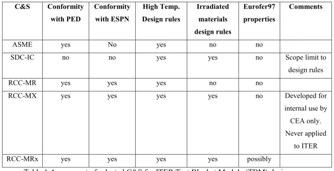
A multi-code approach has been applied for the selection of C&S for ITER in vessel components (table 1). This is consistent with the approach used for ITER mechanical components (4).
C&S Conformity with PED Conformity with ESPN High Temp. Design rules Irradiated materials design rules Eurofer97 properties Comments
ASME yes No yes no no
SDC-IC no no yes yes no Scope limit to
design rules
RCC-MR yes yes yes no no
RCC-MX yes yes yes yes no Developed for
internal use by CEA only. Never applied
to ITER
RCC-MRx yes yes yes yes possibly
Table 1 Assessment of selected C&S for ITER Test Blanket Module (TBM) design.
For the design of in-vessel components, ITER recommended the use of the ITER Structural Design Criteria for in-vessel Components (SDC-IC). SDC-IC has been developed in order to have a specific code covering all the features of plasma-facing components. In particular, SDC-IC contains specific rules to take into account the effects of irradiation on structural materials not covered by the ASME BPVC. On the other hand, the scope of SDC-IC is limited to criteria related to design. Rules for manufacturing, quality assurance and examination are instead covered by ASME BPVC.
ASME has published a guide explaining how to meet ESR defined by PED using BPVC Section VIII, but no guidelines were given to meet conformity with the ESPN order (5).
Moreover Eurofer97 steel was included neither in ASME nor in SDC-IC material data sections.
For these reasons, in the past EU TBMs design activities, RCC-MR (10) has been considered as the reference design code for the TBM assembly instead of ASME.
10
RCC-MR has been the reference French code for high temperature reactors and the 2007 edition contained specific appendixes for ITER components as:
-A18- Additional requirements and special instructions for equipment subject to regulations, to cover PED and ESPN requirements;
-A19 ITER vacuum vessel specificities.
Since RCC-MR didn’t cover measures to be taken to prevent damages resulting from irradiation, the use of SDC-IC was still necessary for TBMs. This approach however was still not satisfactory because: – design rules addressing the effects of irradiation in SDC-IC have been developed mainly for the 316L(N)-IG steel grade on which the design of the ITER blanket is based (5). The mechanical properties of Eurofer97 are very different from those of austenitic steels. The validity/degree of conservatism of the rules defined in SDC-IC needs therefore to be verified for RAFM steels;
– Eurofer97 steel was included neither in RCC-MR nor in SDC-IC material data sections.
Concerning neutron-irradiation effects, a possible alternative to SDC-IC has been RCC-MX (11), an extension of the MR code developed for internal use by CEA. Indeed, the 2012 edition of RCC-MR called RCC-RCC-MRx (2) include RCC-MX specific rules for irradiated materials in order to have a single code suited for the design of all nuclear components to be operated in next generation reactors. Eurofer97 steel is included in the code, allowing the use of RCC-MRx as the sole code for the design and manufacturing of TBMs (5).
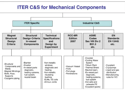
In fig. 1 is shown a schematic diagram illustrating the selection of the specific C&S for the ITER mechanical components (4). Mechanical components include vessels, piping, tanks, pumps, valves, heat exchanges etc. and relative supports.
11
Fig 1 Schematic diagram of C&S for the ITER mechanical components
The following table 2 describes which materials are taken into account in ASME-BPVC, RCC-MRx and SDC-IC codes.
Materials ASME-BPVC RCC-MRx SDC-IC
CuCrZr Other Cu alloys covered
(e.g.70Cu-30Ni) no irradiation data
Not covered Partially covered
Eurofer97 Other 9Cr steels covered
(e.g.9Cr-1Mo) no irradiation data
Covered in probatory rules (creep data limited)
No irradiation data
Not covered
ODS steel Not covered Not covered Not covered
W-Cu Laminates Not covered Not covered Not covered
W&W-alloys Not covered Not covered Partially covered
Al-alloys Several grades covered
(e.g.95154) no irradiation data
Several grades covered (e.g.6061-T6) no irradiation data
Not covered
Zr-alloys Several grades covered
(e.g. UNS R60702) no irradiation data
Several grades covered (e.g.Zircaloy 2) FM data limited
Not covered
12
2.3 Structural Design Criteria for In-vessel Components (SDC-IC)
The ITER Structural Design Criteria for In-vessel Components (SDC-IC) (4) contains rules for structural design of the blanket, divertor and in-vessel parts of various ITER systems (Fig. 1).
The SDC-IC are based on the RCC-MR code and extensive modifications have been provided to include unique structure of ITER components, useful features of other codes (in particular ASME), and national requirements to address the unique features of these components.
These criteria were developed because existing industrial codes are not applicable to the ITER in-vessel components. The structure and the environment of the in-vessel components of ITER have a number of unique features. In particular, the neutron irradiation has a number of effects on material properties, including:
– Time dependent material properties;
– Embrittlement of the material (reduced ductility and fracture toughness), – Irradiation-induced creep;
– Swelling (at specific conditions).
SDC-IC consists of the main Design Criteria document and nine appendices. The main document includes definitions and classifications of different damage and failure modes, type of stresses, joints, thermal creep phenomena, buckling, etc.
The other parts of document include:
- Design rules for general single layer homogeneous structures at low and elevated temperatures, - Rules for welded joints and rules for bolts;
-Design rules for multilayer heterogeneous structures are also included, but they are limited to only low temperature application;
- Rules for irradiated materials are described;
-For materials with reduced ductility, secondary and peak stresses become more important. -Direct limits on secondary and peak stresses that account for both the stress and strain limits of the material; -Rules to prevent failure by plastic flow localization, to limit the elastically calculated primary plus secondary membrane stress intensity. In a similar fashion, to prevent local failure due to exhaustion of ductility, the primary membrane plus bending plus secondary stress is limited. Both limits depend on uniform elongation of material after irradiation.
13
Appendix A, Materials design limit data, currently includes the data for the following materials– austenitic steel 316L(N)-IG (ITER Grade), CuCrZr alloy, dispersion strengthened Cu alloy, Alloy 718, Ti-6Al-4V alloy, precipitation hardened steel 660, beryllium, tungsten, carbon fibre composites, NiAl bronze, austenitic steel XM-19, standard austenitic 316L steel, pure Cu.
Appendix B, Guideline for analysis, provides analysis methods and guidelines of the design rules of SDC-IC.
Appendix C, Rationale or justification of the rules, includes the background information including references to literature that provided the foundation for the rules proposed in the SDC-IC.
Currently the scope of SDC-IC is limited to criteria related to design. Standard manufacturing rules (e.g. welding, forming and non-destructive examination) are based on EU harmonized standards.
2.4 ASME III for nuclear pressure components
At the beginning of the XXst century, after several steam boiler explosions in the United States, the American Society of Mechanical Engineers (ASME) appointed a committee to formulate a standard specification for the construction of steam boilers and other pressure vessels and for the care of same in service.
With time, these rules evolved into the Boiler and Pressure Vessel Code (BPVC) including section III dedicated to nuclear vessels (rules for construction of nuclear power plant components). The first edition (1915) was 114 pages long while the 2001 edition is about 16000 pages long. This to give an idea of large amount of work and experimentation it contains.
Following a brief history of its evolution.
-1915: first publishing of "Rules for the construction of stationary Boiler and For Allowable Working pressures", design factor =5 (allowable stress = specified tensile /design factor). Section I for fired vessel, Section VIII pressure vessels (mainly for the petrochemical industry).
-1942-45 World War II due to steel shortages the design factor is reduce to 4. This was justified (a posteriori) by the use of better material and improved non-destructive examination method.
14
-1955: review aiming to reduce fabrication costs (design factor 3 or 3.5) mainly for the chemical industry (Section VIII). The safety was maintained by (what appears to be now the cornerstones of the code):
o Material selection; o Fracture toughness; o Rules for fatigue;
o Extensive non-destructive;
-1963: Section III dedicated to the Nuclear industry is published with the Pressurized Water Reactor and Boiling water reactor in mind (T<800°F<430°C). It is basically a simplified version of Section VIII (only steam and water).
-1976: issue of Criteria for the Design of Elevated temperature Class 1 components (effect of thermal creep) which will become subsections NH. Oak Ridge N.L. was developing breeder reactor at the time and was supporting this development.
1983: ASME Code is published in both metric units and US customary units (inch, psi) as previously.
ASME III was accepted by the Atomic Energy Commission (in 1963). It is now legally incorporated by reference by the United States Nuclear Regulatory Commission see: Title 10, Code of Federal Regulations § 50.55a Codes and standards. Alternatives are accepted.
The last version was released in 2015 (12).
In 2001, after the introduction of the European Equipment Directive (PED), ASME published a guide to ASME stamp holders explaining how to meet ESR of the directive using ASME Section VIII Division 1.
2.4.1 ASME - Section III - Division 4 for fusion energy devices
ASME Section -III 2015 edition is composed of 5 divisions (13):
− Div1: Class 1, 2, 3 & MC Components; Supports; Core Support Structures; and Class 1 Components in Elevated Temperature Service;
15
− Div2: Concrete Containments;
− Div3: Containments for Transportation and Storage of Spent Nuclear Fuel and High Level Radioactive Material and Waste;
− Div4: Fusion Energy Devices (in development); − Div5: High Temperature Reactors.
Division 4 is developing rules for components that are considered part of the pressure boundary and/or structural integrity of a fusion system .
The target is to issuance of first draft of fusion component rules by the 2015 BPV Edition. The recommended structure for this Division 4 is shown in the following figure.
Fig. 2- Recommended structure for ASME Section III – Div. 4
2.5 RCC-MR
16
design and construction rules for mechanical equipment of Fast Breeder Reactors Nuclear Islands including high temperature applications. On request of the ITER the scope of the code was enlarged to include the ITER vacuum vessel (VV).
The fourth edition of the RCC-MR code has been issued in October 2007 by AFCEN. In addition to including in the scope the ITER VV, the issue of the new 2007 edition was driven by needs of:
- Application in the code of European harmonized standards instead of French AFNOR standards; - Introduction of requirements of the ESP and ESPN;
- Improvement of the design rules based on R&D results.
For application of the RCC-MR code to the ITER vacuum vessel, the following features shall be noticed:
– materials: from the beginning of the VV design development, austenitic steel type 316L(N)-IG has been selected based on steel with controlled nitrogen from the RCC-MR code, edition 1985.
The main driving force for the selection of this material from similar austenitic steels (316L, 316LN, etc.) is its high minimum tensile mechanical properties (combined with good toughness), that results in high stress intensity. In RCC-MR edition 2007 the steel grade is X2CrNiMo17-12-2 with controlled nitrogen content. The 316L(N)-IG has specific requirements for Co, Nb and Ta and lower limit for S and P;
– The design of the ITER VV is a box type of structure. Special rules for box types of structure have been developed in previous editions of RCC-MR for Class 1 components. In edition 2007 similar rules for Class 2 components have been introduced,
– based on features of box type structure, four categories of welded joints for VV have been proposed, – RCC-MR edition 2007 includes rules for different type of bolted Joints.
-Appendix 18 of RCC-MR introduces the requirements of the Pressure Equipment Directive and the ESPN.
- Appendix A19 gives complementary requirements specific for the design of the ITER vacuum vessel. The vacuum vessel is classified as a Class 2 welded box structure which allows to reflect the double shell assembly and to categorize the type of authorized welded joints. In accordance with ESPN, the ITER vacuum vessel is classified as multi-chamber equipment with pressure Category IV and nuclear level N2.
17
2.6 RCC-MX
The RCC-MX is a design and construction code developed in the context of the JHR (Jules Horowitz reactor) project, by CEA and AREVA (AREVA TA and AREVA NP) (11, 14). This code dedicated to research reactor components, their auxiliaries and irradiation devices integrated the lessons learned of several tenths (60 years) of French research reactor design and operation and was founded on up-to-date standards ( ISO International and or EN European standards). A huge effort has been done by collecting the irradiated material data and is continued through an important characterization program of material especially focused on irradiated material properties and aluminium and zirconium alloys.
2.7 RCC-MRx
The RCC-MRx code (2, 3, 15 and 16) constitutes a single document that covers the design and construction of components for high temperature reactors and research reactors and the associated auxiliaries, examination and handling mechanisms and irradiation devices.
The design rules were adapted to cover the mechanical resistance of structures close to neutron sources that can also operate in significant thermal creep conditions.
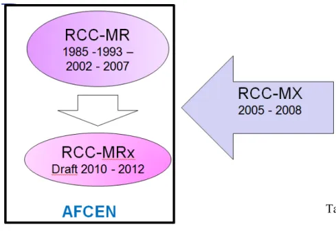
The RCC-MRx code was first issued in 2009 from the merging of the RCC-MR code, 2007 edition, devoted to high temperature reactor and ITER vacuum vessel, and the RCC-MX code, edition 2008, dedicated to research reactors and related devices (table 3). A new version of the RCC-MRx code has been published at the end of 2012.
18
The scope of application of the RCC-MRx design and construction rules (2) is limited to mechanical components:
• considered to be important in terms of nuclear safety and operability,
• playing a role in ensuring leaktightness, partitioning, guiding, securing and supporting,
• containing fluids such as pumps, valves, pipes, bellows, compartmentalized structures, heat exchangers and their supports.
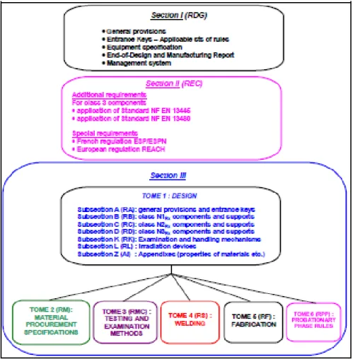
To enable the introduction of complementary design and construction rule sets such as those contained in Standards EN 13445 (Unfired pressure vessels) and EN 13480 (Metallic industrial piping), the usual RCC code format has been modified with the creation of three sections (Figure 3):
- Section I: general provisions common to the entire code;
- Section II: additional requirements for the alternative use of other applicable rule sets (Standards EN 13445 and EN 13480 for instance) for Class 3 components, and special instructions for components subject to local regulations such as pressure equipment or nuclear pressure equipment;
- Section III: set of applicable rules with six Tomes:
Tome 1 being sub-divided into subsections: it contains the design and construction rules and comprises
subsections which are alphanumerically numbered:
• Volume A: general provisions for Section III,
• Volume B (C and D): design rules for class N1Rx (N2Rx and N3Rx) components and supports of the nuclear reactor and its auxiliary systems,
• Volume K: design rules for examination, handling or drive mechanisms, • Volume L: design rules for irradiation devices
• Volume Z: technical appendixes associated to Tome 1
Tomes 2 to 5 contain the rules corresponding to various technical areas:
Tome 2: part and product procurement specifications,
Tome 3: destructive tests and non-destructive examination methods,
Tome 4: qualifications for welding operations and welding procedures and their application, Tome 5: manufacturing operations other than welding,
Tome 6: rules in probationary phase
The three classes of design and construction proposed (N1Rx, N2Rx and N3Rx) correspond to decreasing levels of assurance of ability to withstand different types of mechanical damages to which the component might be exposed as result of loading corresponding to specific operating conditions.
19
Fig. 3 General Plan of RCC-MRx code
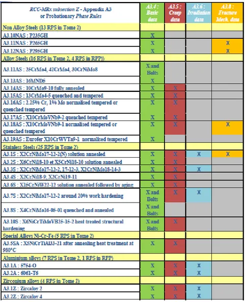
New materials, different from the steels used in Pressurized Water Reactors (PWR) and Sodium Fast breeder Reactors (SFR), such as alloys of aluminium and zirconium can meet requirements for neutron transparent materials of research or irradiation reactors (RR) (table 4).
For instance, for reflectors, the substitution of 10 mm of steel tube for 10 mm of zirconium or aluminium alloy tubes makes it possible to potentially obtain 50% more thermal flux. It is therefore necessary to make sure that suitable compromises are made between mechanical strength, thermal control (gamma heating of 10 to 20W/g in core) and activation effect control (e.g. cobalt content). Although the initial editions of the RCC-M and RCC-MR rely greatly on the French NF series standards at the time, the rapid development of European standards (EN and EN ISO) covering all subjects such as procurement, destructive and non-destructive testing, welding and even design, leaded to carry out a considerable amount of work to integrate these new standards into the RCC-MR 2007 and RCC-MX 2008. This update of the standards was found in the RCC-MRx code.
20
Table 4 Mechanical characteristics available in Appendix A3
The following table 5 shows the correspondence of ASME Section III and RCC MRx code.
Table 5 Correspondence between ASME III and RCC-MRx (16)
21
The added values of RCC-MRx are:
- the use of specific materials (aluminium alloys, Zirconium alloys, etc.) required to manage compromises involving mechanical behaviour, low activation under neutron fluxes, low capture of neutron fluxes, thermal conductivity, etc. specific of research reactors;
- modern welding processes (Electron Beam, laser, diffusion); - taking into account the thermal creep:
• high temperature (up to 700° C depending on the materials),
• other material such as aluminium alloys at intermediate temperature; - consistent with the PED and ESPN regulations;
- taking into account:
• important level of irradiation inducing an evolution of the characteristics of materials (stainless steel, aluminium or zirconium alloys),
• update European standards such as “harmonised standard”.
2.7.1 Promotion of the code in Europe
AFCEN has been working with the EC, in the framework of Sustainable Nuclear Energy Technology Platform (SNE-TP), to promote RCC-MRx as the European code for the design and construction of the next generation of nuclear plants.
The first applications of this code will concern innovative prototypes and demonstration plants supported by the European Sustainable Nuclear Industrial Initiative (ESNII) to be built in Europe during the next decade.
Thus in 2011, it was decided to federate the stakeholders of these projects, and other interested parties (e.g. ITER) in the development of the dedicated code, namely RCC-MRx, through a CEN Workshop (CEN/WS 64) leaded by AFCEN. The workshop was financially supported by the European Commission.
In parallel, the CEN-CENELEC Focus group investigated the situation of nuclear standards in Europe and the potential need to create a European technical structure dedicated to this area under its umbrella. Based on the results of the CEN Workshop 64 and the recommendations of the CEN-CENELEC Focus Group, in April 2013 the European Commission, in the framework of ENEF (European Nuclear Energy
22
Forum), decided to support a CEN/WS 64 phase 2 with the target to enlarge the scope to the codes for mechanical equipment and civil engineering of GEN II to GEN IV nuclear installations. Indeed, seeing the perspective of the Long Term Operation for GEN II NPPs and the potential new NPPs of GEN III, the aim would be to offer an opportunity to a wide range of stakeholders to gain a deep understanding of the AFCEN codes and their evolution process, to allow them to define their long term requirements for the codes modification and the adaptation to their needs. It would also lead to the definition of pre-normative research priorities. At the end this would help initiating the harmonization process of codes at EU level (17).
3. Conclusions
In the document the main important C&S available for fusion reactors have been investigated with particular attention on RCC-MRx since this code is emerging as a European code for mechanical components of nuclear installations. Also a comparison with other structural codes for nuclear components has been done.
Acknowledgments
This technical report is mostly derived from my master thesis on “Fusion energy – science and engineering”. I thanks you all colleagues for their help and support. In particular I would like to express my sincere gratitude to my master tutor ing. G. Mazzone for the continuous support, for his patience, motivation and enthusiasm.
23
References
(1) M. Porton et alii, “Structural design criteria development needs for a European Demo”, Fusion Science and Technology, Vol. 66 July/August 2014
(2) “Code of Design and Construction Rules for Mechanical Component in Nuclear Installations (RCC-MRX)” Ed. 2012 + 1st addendum December 2013, AFCEN 2013
(3) T. Lebarbè et alii, “ Afcen RCC-MRx code: specificities and CEN-Workshop”, Transactions, SMiRT, 21, Nov. 2011, New Delhi
(4) V. Barabash et alii, “Codes and standards and regulation issues for design and constructio of the ITER mechanical components”, Fusion Engineering and Design 85 (2010) 1290-1295 (5) G. Aiello et alii, “Assessment of Design Limits and Criteria Requirements for Eurofer
structures in TBM Components”, Journal of Nuclear Materials 414 (2011) 53-68
(6) Directive 97/23/EC of the European Parliament and of the Council of 29 May 1997 on the approximation of the Laws of the Member States concerning pressure equipment
(7) French Order dated 12th December 2005 concerning nuclear pressure equipment (Equipment Sous Pression Nuclèaires- ESPN)
(8) The French Order concerning Quality of Design, Construction and Operation of Basis Nuclear Installations, 10th August 1984
(9) G. Sannazzaro et alii, “Development of design criteria for ITER in-vessel components”, Fusion Engineering and Design 88 (2013) 2138-2141
(10) RCC-MR 2007 – Design and Construction Rules for Mechanical Components of Nuclear Installations, 2007 Afcen Code, www.afcen.com
(11) RCC-MX 2008 - Design and Construction Rules for Mechanical Components of Research Reactors and their experimental devices, 2008 CEA Code
(12) J.C. Venchiarutti, “European study on the feasibility to develop standardized rules for the design and construction of Generation IV nuclear reactors”, 12-12-212, www.Afnor.org (13) W.K. Sowder, R. W. Barnes, “ASME Division 4 Fusion Energy Devices” , ICONE20,
Anaheim, USA, 2012
(14) L. Guerrini, “EU-TBM team - Guerrini presentation on RCC-MR and RCC-MX codes and Eurofer material”, ITER_D_KLHHZF, 2013
(15) F. Corsi e alii, “ Verifica della validità del diagramma di “efficacia” in RCC-MRx”, Ricerca di sistema elettrico, ENEA Rds/2011/164
(16) C. Petesch “RCC-MR/RCC-MRx”, AFCEN, Korea conference 2011
Servizio Promozione e Comunicazione Lungotevere Thaon di Revel, 76 - 00196 Roma
www.enea.it Pervenuto il 2.12.2015
Stampato presso il Laboratorio Tecnografico ENEA - C.R. Frascati Finito di stampare nel mese di dicembre 2015