Alma Mater Studiorum – Università di Bologna
DOTTORATO DI RICERCA IN
Ingegneria Civile, Chimica, Ambientale e dei Materiali
Ciclo XXIX
Settore Concorsuale di afferenza: 08/B3 Settore Scientifico disciplinare: ICAR/09
TITOLO TESI
On the Seismic Behavior of Ground-Supported
Circular Silos Containing Grain-like Material
Presentata da: Luca Pieraccini
Coordinatore Dottorato
Relatore
Prof. Luca Vittuari
Prof. Ing. Tomaso Trombetti
Correlatore
Prof. Ing. Stefano Silvestri
Abstract
This thesis is focused on the analysis of the seismic response of flat-bottom cylindrical grain-silos. Part A constitutes an updated state-of-the-art on the structural seismic design of flat-bottom cylindrical grain-silos, Part B critically analysis the theoretical framework developed in the last decade at the University of Bologna by the research work coordinated by Prof. Trombetti and the experimental tests conducted in 2012-2013 for its experimental verification, whilst Part C provides some refinement on the theoretical framework and some further insight into the dynamic behavior of flat-bottom cylindrical grain-silos, representing the main scientific contribution of the work.
Part A begins with a comprehensive review of the main analytical, numerical and experimental researches devoted to the study of the static and dynamic behavior of flat-bottom cylindrical grain-silos, together with a review of the current design code provisions for the seismic design of grain-silo structures. A comparison between the current code provisions on the seismic behavior of flat-bottom grain-silo structures and the actual body of knowledge is provided.
Part B is focused on the previous research works conducted by Prof. Trombetti and co-workers in the year 2012-2013. First, the theoretical study on the horizontal forces produced by grain-like material inside silos during earthquakes is presented. Then, the experimental investigation conducted via shaking-table tests at the EQUALS laboratory of the University of Bristol (ASESGRAM project) are reported. Finally, the analytical-experimental correlation study for the verification of the original analytical formulation is illustrated.
Part C presents some refinements of the original analytical formulation for the estimation of the maximum lateral actions developed during an earthquake as well as an analytical formulation for the estimation of the fundamental period of vibration of flat-bottom circular grain-silos. Finally, the results of a preliminary on-field experimental campaign on a real silo structure are illustrated.
Acknowledgements
I am very grateful to my supervisors Prof. Tomaso Trombetti and Prof. Stefano Silvestri for the opportunity to undertake this Ph.D. course, which represents a tremendous experience of personal growth, and for their continuous technical guidance during the entire period of my research work in Bologna.
I am thankful to all my Department colleagues (Giada, Simonetta, Roberta, Michele, Antoine) for sharing ideas and providing a congenial and friendly working atmosphere.
I also want to thank my parents, my brothers and my sister for their constant support. A special thank goes to my wife, Andrea, for her constant support and lovely encouragement during all these last three years.
Alla famiglia di ieri, di oggi, e di domani
Table of contents
1. Introduction ... 1
1.1 Background and motivations ... 1
1.2 The objectives of the research work ... 2
1.3 Text organization... 2
PART A: Updated state of the art ... 7
2. Literature review of the analytical and the numerical studies on the dynamics of flat-bottom silos containing grain-like material ... 8
2.1 Analytical studies ... 8
2.2 Numerical studies ... 18
2.3 Critical considerations ... 33
3. Literature review of the experimental tests on the dynamics flat-bottom silos containing grain-like material and on-field reconnaissance campaigns ... 42
3.1 Experimental tests on horizontally shaken granular material ... 42
3.2 Dynamic tests on circular flat-bottom ground-supported grain-silos... 45
3.3 On-field reconnaissance data after strong earth motions ... 58
3.4 Critical considerations ... 61
4. Current code provisions for the structural seismic design of grain-silos ... 67
4.1 Uniform Building code UBC (1994) provisions ... 67
4.2 ACI 313-97 (1997) provisions ... 68 4.3 NCh2369 (2003) provisions ... 68 4.4 Eurocode 1998-4 (2006) provisions ... 69 4.5 FEMA P-750 (2009) provisions ... 72 4.6 ASCE 7-10 (2010) provisions ... 73 4.7 AIJ (2010) provisions ... 74 4.8 Critical considerations ... 75
5. Current body of knowledge and the challenges ... 81
PART B: Previous research work ... 88
6. The theoretical studies conducted at the University of Bologna ... 89
6.1 Problem formulation and basic assumptions ... 89
6.2 Dynamic equilibrium in accelerated conditions ... 99
6.3 Specialization to the case of constant vertical profiles of both the vertical and the horizontal earthquake accelerations... 106
6.4 Specialization to the case of null vertical and horizontal earthquake accelerations: the static case ... 107
6.5 Portions of grain relative to the behavior under accelerated conditions ... 108
6.6 Limits of validity of the proposed analytical formulation... 108
6.7 The shear forces and the bending moments on the silo wall ... 110
6.8 Graphic representations of the pressures, the two grain portions inside the silo and the wall actions ... 111
6.9 Critical considerations ... 127
7. The experimental campaign conducted at the EQUALS laboratory ... 130
7.1 The rationale behind the experimental campaign ... 130
7.2 The experimental campaign ... 132
7.3 Results of the experimental campaign ... 144
7.4 Rupture of the silo specimen ... 162
7.5 Critical considerations ... 164
8. Experimental-analytical correlation study ... 168
8.1 The experimental base bending moment ... 168
8.2 The influence of the wall–grain friction coefficient... 169
8.3 The comparison between the experimental and predicted values of the base bending moment ... 173
PART C: Research developed ... 178
9. Refinements to the original theoretical formulation ... 179
9.1 Problem formulation and basic assumptions ... 179
9.2 Dynamic equilibrium in accelerated conditions ... 183
9.3 Specialization to the case of constant vertical profiles of both the vertical and the horizontal earthquake accelerations... 190
9.4 Specialization to the case of null vertical and horizontal earthquake accelerations: the static case ... 191
9.5 Portion of grain relative to the behavior under accelerated conditions ... 191
9.6 Limits of validity of the proposed analytical formulation... 192
9.7 The shear forces and the bending moments on the silo wall ... 195
9.8 Graphic representations of pressures, grain portions interacting with the silo and wall actions ... 196
9.9 On the limits of validity and the assumptions ... 215
9.10 Comparison with the experimental evidences ... 219
9.11 Critical considerations ... 220
10. On the fundamental period of vibration of ground-supported grain-silos .... 223
10.1 Problem formulation and basic assumptions ... 223
10.2 Analytical developments ... 228
10.3 Experimental verification and numerical validation of the analytical formulation ... 236
10.4 A simple code like-formula steel silos ... 240
10.5 A modeling technique based on the analytical formulation ... 241
10.6 Critical consideration ... 244
11. An experimental campaign on a real steel silo containing maize grain ... 247
11.1 Objectives ... 247
11.3 Experimental result of the measurements ... 263
11.4 Reconstruction of the internal actions in the structural members ... 272
11.5 Comparison between reconstructed actions and predicted actions ... 283
11.6 Critical considerations ... 285
12. Conclusions and future developments ... 289
12.1 Main conclusions of part A ... 289
12.2 Main conclusions of part B ... 290
12.3 Main conclusions of part C ... 290
List of Figures
Figure 2.1 - Physical idealized model of Janssen theory (1895) for static conditions. (a) Vertical cross-section. The forces are referred to the grain. (b) Horizontal cross-section. On the left the forces are referred to the grain, on the right to the wall ... 10 Figure 2.2 - Analytical model by Younan and Veletsos (1988) and (b) Durmuş and Livaoglu (2015) (Figure adapted by Younan and Veletsos 1988 and Durmuş and Livaoglu 2015) ... 16 Figure 2.3 - FE models: (a) stave-silo model by Sasaki and Yoshimura (1992) and (b) grain-silo model by Holler and Meskouris (2006) ... 29 Figure 3.1 - Typical setup for experimental tests on horizontally shaken granular material: (a) thin-layer; (b) full 3D geometry ... 44 Figure 3.2 - Typical experimental resonance curve ... 54 Figure 3.3 – (a) Test setup used by Harris and Von Nad (1985) and (b) test setup and instrumentation used by Sakai et al. (1985) with shaking table ... 54 Figure 5.1 - Actual behavior vs scientific knowledge vs code provisions: (a) grain silos; (b) frame structures ... 83 Figure 6.1 - Geometry of the flat-bottom ground-supported circular grain-silo and the reference system considered. a) Vertical view; b) Plan view ... 90 Figure 6.2 – a) Idealized system. b) Mutual forces exchanged between two adjacent grains, between the grain and the silo wall, and between the grain and the silo base ... 90 Figure 6.3 - Representation of the mutual actions exchanged between consecutive grains, between the grain and the silo wall, and between the grain and the silo bottom ... 92 Figure 6.4 - (a) Actual distribution of pv,GG(z), (b) the schematization by Janssen (1895). ... 93 Figure 6.5 - Accelerated conditions: silo subjected to gaevg and to aehg ... 95 Figure 6.6 - External torus (red hatching) and internal disk (blue hatching) of the grain layer. (a) Vertical section, (b) plain view. ... 96
Figure 6.7 - Physical idealized model of the analytical formulation for accelerated conditions. (a) Vertical cross-section. The forces are referred to the grain. (b) Horizontal cross-section. On the left the forces are referred to the grain, on the right to the wall ... 97 Figure 6.8 - Vertical longitudinal section: a) schematic trend of s(z,); b) vertical and horizontal actions operating on disk D and on the symmetrical elements E ... 100 Figure 6.9 - Horizontal cross-section: horizontal actions operating on the symmetrical elements E ... 101 Figure 6.10 - Heightwise variation of the normalized grain-wall normal pressures for Janssen (J) and the proposed analytical formulation (O) in static conditions for squat silos containing barley, wheat and cement clinker. ... 113 Figure 6.11 - Heightwise variation of the normalized grain-wall overpressures for Eurocode 8 (EC8), the Trahair formulation (T), the proposed analytical formulation (O) in dynamic conditions for squat silo for squat silos containing barley, wheat and cement clinker. ... 114
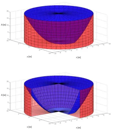
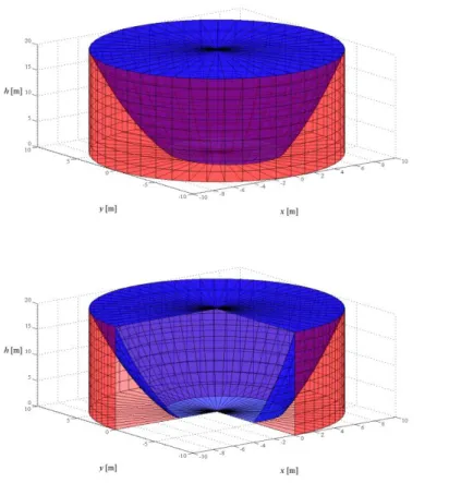
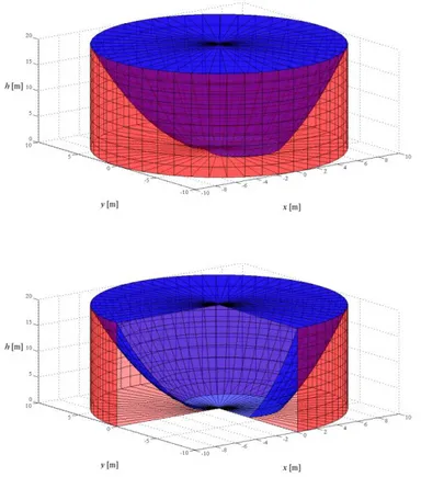
Figure 6.12 - Horizontal cross-section of the considered silo at height z = 0.50H and z = 0.95 H for the squat silo containing wheat ... 116 Figure 6.13 - Horizontal cross-section of the considered silo at height z = 0.50H and z = 0.95 H for the squat silo containing wheat ... 117 Figure 6.14 - Horizontal cross-section of the considered silo at height z = 0.50H and z = 0.95 H for the squat silo containing cement clinker ... 118 Figure 6.15 -Three-dimensional view of portion D (in blue) and of portion E (in red) of the flat-bottom squat silo containing barley for the proposed analytical formulation: (a) sectioned view and (b) overview ... 120 Figure 6.16 - Three-dimensional view of portion D (in blue) and of portion E (in red) of the flat-bottom squat silo containing wheat for the proposed analytical formulation: (a) sectioned view and (b) overview ... 121 Figure 6.17 - Three-dimensional view of portion D (in blue) and of portion E (in red) of the flat-bottom squat silo containing cement clinker for the proposed analytical formulation: (a) sectioned view and (b) overview ... 122
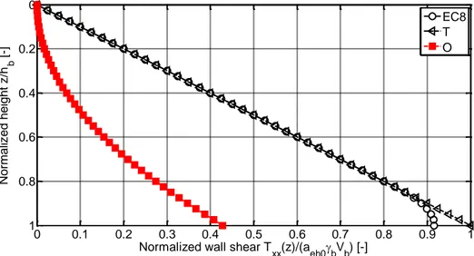
Figure 6.18 - Heightwise variation of the normalized wall shear for Eurocode 8 (EC8), the Trahair formulation (T), the proposed analytical formulation (O) in dynamic conditions for squat silo containing barley ... 123 Figure 6.19 - Heightwise variation of the normalized wall shear for Eurocode 8 (EC8), the Trahair formulation (T), the proposed analytical formulation (O) in dynamic conditions for squat silo containing wheat ... 124 Figure 6.20 - Heightwise variation of the normalized wall shear for Eurocode 8 (EC8), the Trahair formulation (T), the proposed analytical formulation (O) in dynamic conditions for squat silo containing cement clinker ... 124 Figure 6.21 - Heightwise variation of the normalized wall bending moment for Eurocode 8 (EC8), the Trahair formulation (T), the proposed analytical formulation (O) in dynamic conditions for squat silo containing barley ... 125 Figure 6.22 - Heightwise variation of the normalized wall bending moment for Eurocode 8 (EC8), the Trahair formulation (T), the proposed analytical formulation (O) in dynamic conditions for squat silo containing wheat ... 126 Figure 6.23 - Heightwise variation of the normalized wall bending moment for Eurocode 8 (EC8), the Trahair formulation (T), the proposed analytical formulation (O) in dynamic conditions for squat silo containing cement clinker ... 126 Figure 6.24 - Values of the effective mass as function of the slenderness ratio for the Eurocode 8 provisions (EC8), the Trahair formulation (T) and the proposed analytical formulation (O) for different ensiled bulk solids... 127 Figure 7.1 - Example of low frequency sinusoidal input ... 132 Figure 7.2 - The analytical model, the tested specimen and the real silo ... 132 Figure 7.3 – (a) The specimen with smooth walls. (b) The specimen with roughened wall. ... 133 Figure 7.4 - Drawings of the positions of the bolt connections between bottom plate and vertical polycarbonate sheets along the base of the silo (XZ plan view) for the smooth wall specimen, August 2012 session (measurements are expressed in millimeters) ... 134 Figure 7.5 - Drawings of the positions of the bolt connections between bottom plate and vertical polycarbonate sheets along the base of the silo (XZ plan view) for the roughened
wall specimen, January-February 2013 session (measurements are expressed in millimeters)
... 134
Figure 7.6 - a) Base connections of first session of tests, b) Base connections of second and third session of tests ... 135
Figure 7.7 - Stress-strain relationship for the polycarbonate of the cylinder ... 135
Figure 7.8 - (a) The specimen filled with Ballottini glass up to 0.6 m. (b) The specimen filled with Ballottini glass up to 1.2 m. ... 136
Figure 7.9 - Shear-box test results: (a) shear stress-vertical normal stress ratio versus horizontal displacement; (b) dilatancy versus horizontal displacement ... 137
Figure 7.10 - (a) Smooth interface tests results. (b) Rough interface tests results. .... 138
Figure 7.11 - (a) The instrumentation in the first configuration. (b) The instrumentation in the second and third configuration. ... 143
Figure 7.12 – (a) Detail of the position of the accelerometers along the height of the silo; (b) details of the circumferential and vertical strain gauges ... 143
Figure 7.13 - The silo specimen; (b) the setup of the instrumentations (c) the pouring of the Ballottini glass material ... 144
Figure 7.14 - Measurement of grain settlements ... 145
Figure 7.15 - Grain heights at the end of selected single tests. ... 145
Figure 7.16 - Transfer functions for the empty silo for tests N1 and N3... 146
Figure 7.17 - Transfer functions for the first configuration for tests N1 and N4 ... 148
Figure 7.18 - Transfer functions for the second configuration silo for tests N1... 149
Figure 7.19 - Transfer functions for the third configuration for test N1 ... 149
Figure 7.20 - Accelerometers on the silo wall at different heights: a) left side and b) right side for the first configuration of tests. ... 152
Figure 7.21 - (a) Acceleration profiles for sinusoidal tests at 1Hz. (b) Acceleration trend for sinusoidal tests at 1Hz. ... 153
Figure 7.22 - (a) Acceleration profiles for sinusoidal tests second configuration. (b) Acceleration trend for sinusoidal test for the third configuration. ... 155
Figure 7.23 - Vertical strains at different heights for the first (a), second (b) and third (c) configurations of tests. ... 158 Figure 7.24 - Vertical strains at different heights for the first configuration for S9 test at the right side (y= -0.60 m). ... 158 Figure 7.25 - Infiltration of Ballottini glass along the vertical junction of the two polycarbonate sheets. ... 159 Figure 7.26 - Vertical strains at z'=0.14 m for the 1 Hz sinusoidal S4 input. ... 159 Figure 7.27 - Vertical strains at different heights for the third configuration for S25 test at the right side (y= -0.60 m). ... 160 Figure 7.28 – Pseudo-acceleration spectrum of the table acceleration time-history for Test E18 (South Iceland earthquake) and fundamental frequencies of the grain-silo system. ... 161
Figure 7.29 - (a) Acceleration profiles for seismic tests. (b) Acceleration trend for seismic tests. ... 162 Figure 7.30 - Spilling of the Ballottini glass from the crack of the wall after the failure ... 163
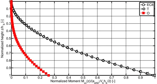
Figure 7.31 - (a) Frontal view of the crack shape; (b) lateral view of the crack shape; (c) Detail of the crack close to the bolted connection; (d) internal view of the crack shape .. 163 Figure 8.1 - Plan view of the strain gauges position. ... 169 Figure 8.2 - Comparison between the first and the third configuration bending moments at (a) 0.2g and (b) 0.3g. ... 170 Figure 8.3 - Base bending moment vs. table acceleration for all the three test configurations. ... 171 Figure 8.4 - Normalized base bending moment vs. table acceleration for the first and the third test configurations. ... 172 Figure 8.5 - Comparison between the reconstructed experimental bending moment as obtained in the first test configuration for the 1 Hz sinusoidal input and the predicted values by the proposed analytical formulation, the Eurocode 8 provisions and the Trahair formulation. ... 173
Figure 8.6 - Comparison between the experimental bending moment as obtained in the second test configuration for the 1 Hz sinusoidal input and the predicted values by the proposed analytical formulation, the Eurocode 8 provisions and the Trahair formulation. ... 173 Figure 8.7 - Comparison between the experimental bending moment as obtained in the third test configuration for the 2 Hz sinusoidal input and the predicted values by the proposed analytical formulation, the Eurocode 8 provisions and the Trahair formulation... 174 Figure 8.8 - Comparison between the experimental bending moment as obtained in the first test configuration for the three earthquakes: Duzce, Friuli, South Iceland and the predicted values by the proposed analytical formulation, the Eurocode 8 provisions and the Trahair formulation... 174 Figure 9.1 - External torus (red hatching) and internal disk (blue hatching) of the grain layer. (a) Vertical section, (b) plain view. ... 181 Figure 9.2 - Physical idealized model for the refined theory for accelerated conditions. (a) Vertical cross-section. The forces are referred to the grain. (b) Horizontal cross-section. On the left the forces are referred to the grain, on the right to the wall. ... 182 Figure 9.3 - Visual comparison of the physical idealized models. On the first line the vertical cross-section. On the second line the horizontal cross-section. (a) Janssen (1895)theory for static conditions, (b) the original analytical formulation (Silvestri et al. 2012) and (c) the refined analytical formulation under accelerated conditions... 182 Figure 9.4 - Vertical and horizontal actions operating on disk D and element E... 184
Figure 9.5 - Horizontal cross-section: horizontal actions operating on an elementary sector of the element E ... 184
Figure 9.6 - Thickness of the hang material on the silo wall and grain-grain pressure distribution on the lateral surface of disk D in static (a) and accelerated conditions (b). ... 187
Figure 9.7 - Trend of the admitted horizontal acceleration as function of the vertical acceleration factor for three different grain-wall friction coefficients according to Eq. (35) (grey line) and to Eq. (37) (black line) ... 194 Figure 9.8 - Heightwise variation of the normalized grain-wall normal pressures for Janssen (J), the Original analytical formulation (O) and the Refined analytical formulation (R) in static conditions for squat silo (=1, red color), intermediate-slender silo (=2, green color) and slender silo (=4, blue color) ... 198
Figure 9.9 - Heightwise variation of the normalized grain-wall overpressures for Eurocode 8 (EC8), the Trahair formulation (T), the Original analytical formulation (O) and the Refined analytical formulation (R) in dynamic conditions for squat silo (=1, red color), intermediate-slender silo ( =2) and slender silo ( =4) ... 200 Figure 9.10 -Horizontal distribution of the normalized overpressures on the wall for the squat silo (=1): (a) at z/hb= 0.50 and (b) at z/hb= 0.95 for Eurocode 8 (EC8), the Trahair formulation (T), the Original analytical formulation (O) and the Refined analytical formulation in accelerated conditions ... 202 Figure 9.11 -Horizontal distribution of the normalized overpressures on the wall for the intermediate slender silo (=2): (a) at z/hb= 0.50 and (b) at z/hb= 0.95 for Eurocode 8 (EC8), the Trahair formulation (T), the Original analytical formulation (O) and the Refined analytical formulation in accelerated conditions ... 203 Figure 9.12 -Horizontal distribution of the normalized overpressures on the wall for the slender silo (=4): (a) at z/hb= 0.50 and (b) at z/hb= 0.95 for Eurocode 8 (EC8), the Trahair formulation (T), the Original analytical formulation (O) and the Refined analytical formulation in accelerated conditions ... 204 Figure 9.13 -Three-dimensional view of portion D (in blue) and of portion E (in red) of the flat-bottom squat silo for the original analytical theory: (a) sectioned view and (b) overview ... 206 Figure 9.14 -Three-dimensional view of portion D (in blue) and of portion E (in red) of the flat-bottom squat silo for the refined analytical theory: (a) sectioned view and (b) overview ... 207 Figure 9.15 -Three-dimensional view of portion D (in blue) and of portion E (in red) of the flat-bottom intermediate-slender silo for the refined analytical theory: (a) sectioned view and (b) overview ... 208 Figure 9.16 -Three-dimensional view of portion D (in blue) and of portion E (in red) of the flat-bottom slender silo for the refined analytical theory: (a) sectioned view and (b) overview ... 209 Figure 9.17 - Heightwise variation of the normalized wall shear for Eurocode 8 (EC8), the Trahair formulation (T), the Original analytical formulation (O) and the Refined analytical formulation (R) in dynamic conditions for squat silo... 210
Figure 9.18 - Heightwise variation of the normalized wall shear for Eurocode 8 (EC8), the Trahair formulation (T), the Original analytical formulation (O) and the Refined analytical formulation (R) in dynamic conditions for intermediate-slender silo ... 211 Figure 9.19 - Heightwise variation of the normalized wall shear for Eurocode 8 (EC8), the Trahair formulation (T), the Original analytical formulation (O) and the Refined analytical formulation (R) in dynamic conditions for slender silo ... 211 Figure 9.20 - Heightwise variation of the normalized wall bending moment for Eurocode 8 (EC8), the Trahair formulation (T), the Original analytical formulation (O) and the Refined analytical formulation (R) accounting for the frictional vertical stresses contribution (continuous line) and without (dashed line) in dynamic conditions for the squat silo ... 213 Figure 9.21 - Heightwise variation of the normalized wall bending moment for Eurocode 8 (EC8), the Trahair formulation (T), the Original analytical formulation (O) and the Refined analytical formulation (R) accounting for the frictional vertical stresses contribution (continuous line) and without (dashed line) in dynamic conditions for the intermediate-slender silo... 213 Figure 9.22 - Heightwise variation of the normalized wall bending moment for Eurocode 8 (EC8), the Trahair formulation (T), the Original analytical formulation (O) and the Refined analytical formulation (R) accounting for the frictional vertical stresses contribution (continuous line) and without (dashed line) in dynamic conditions for the slender silo ... 214 Figure 9.23 - Values of the effective mass as function of the slenderness ratio for the Eurocode 8 provisions (EC8), the Trahair formulation (T) and the proposed analytical formulation (O) for different ensiled bulk solids... 215 Figure 9.24 - Plot of the normalized thickness at the bottom of the silo for: static conditions (green) and accelerated conditions,0.30 (ciano), 0.45 (blue) ... 218 Figure 9.25 - Comparison between the reconstructed experimental bending moment and the predicted values by the original analytical formulation, the refined analytical formulation, the Eurocode 8 provisions and the Trahair formulation for the first configuration. ... 220
Figure 9.26 - Comparison between the reconstructed experimental bending moment and the predicted values by the original analytical formulation, the refined analytical formulation, the Eurocode 8 provisions and the Trahair formulation for the third configuration. ... 220 Figure 10.1 –Volume ratio of the external torus E in dynamic and static conditions considering uniform and linear vertical profile of the horizontal acceleration for different slenderness ratios ... 227 Figure 10.2 – Vertical distribution of the effective mass for uniform and linear vertical profile of the horizontal acceleration for different slenderness ratio (for a = acrit) ... 227 Figure 10.3 – (a) Geometry of a realistic flat-bottom ground-supported circular grain-silo;(b) Geometry of the corresponding equivalent beam ... 230
Figure 10.4 - Comparison of the values of the first fundamental period given by the fully analytical formula of Eq. (20) (solid markers) and the code-like formula of Eq. (23) (dotted line) for silos with various diameter and filled with aggregate ... 241 Figure 10.5 - FE models for the squat silo (=0.65) and the slender silo ( =3.00) with stepwise variation of the wall thickness and uniform equivalent wall density ... 244 Figure 11.1 - Horizontally corrugated vertically stiffened flat-bottomed silo in exam ... 250
Figure 11.2 - a) External view of the horizontally corrugated vertically stiffened silo wall; b) internal view of the silo wall; c) general external view of the silo wall and arrangement of the bolted connections; d) view of the joint between two consecutive vertical stiffeners ... 250 Figure 11.3 - Horizontal levels composed by consecutive horizontally corrugated wall strips ... 251 Figure 11.4 - Example of the reference system for L7PD cross-section composed by two superposed steel profiles. ... 252 Figure 11.5 - Maize delivered by truck ... 254 Figure 11.6 - a) Digital invar micrometer “DEMEC” 250; b) Analogic invar micrometer “DEMEC” 300 ... 255
Figure 11.7 – a) Male reference base of length 250 mm for the positioning of the metal-disks on the structural members; b) female invar reference base for the assessment of the thermal deformation of the instrument ... 256 Figure 11.8 - Instrumentation to measure the temperature of the air and the temperature of the structural members ... 256 Figure 11.9 – Typology of 8 mm long strain gauges mounted on the silo wall and vertical stiffeners ... 256 Figure 11.10 – a) Metal disks glued on the wall and the hat-shaped stiffeners in order to materialize vertical measuring bases; b) example of application of the metal disks on the silo wall ... 259 Figure 11.11 – a) Measuring base along the vertical axis of symmetry of the wall portion enclosed between two consecutive stiffeners; b) measuring base close to vertical stiffeners. ... 259 Figure 11.12 – a) Measuring bases along the front face of the stiffener’s web along the middle vertical axis and along the middle vertical axis of the inclined flange, on the internal face; b) measuring base along the middle vertical axis of the inclined flange, on the external face... 260 Figure 11.13 – Horizontal strain gauge on the apex of a wave on the corrugated wall in correspondence of the measuring base M1 at z* = 1,40 m ... 260 Figure 11.14 – a) Vertical strain gauge placed on the external face of the external profile composing the hat-shaped stiffeners in correspondence of the measuring base O1 at z*= 1,40 m; b) Vertical strain gauge placed on the internal face of the internal profile composing the hat-shaped stiffeners in correspondence of the measuring base I1 z*= 1,40 m. ... 261
Figure 11.15 - a) Example of measurement of the temperature on the wall; b) on the stiffener. ... 263 Figure 11.16 - Measurements on the measuring bases on the elevator ... 264 Figure 11.17 - Trends of the reconstructed vertical stresses of the stiffener at level 16 as given by the measuring bases as a function of the equivalent filling height hb ... 278
Figure 11.18 - Trends of the reconstructed vertical stresses of the stiffener at level 16 as given by the strain gauges as a function of the equivalent filling height hb ... 278 Figure 11.19 - Comparison of the trends of the reconstructed vertical stresses of the stiffener at level 16 given by the measuring bases and the strain gauges as a function of the equivalent filling height hb for: a) the external face and b) the internal face of the stiffener. 279 Figure 11.20 - Trends of the reconstructed vertical stresses of the stiffener at level 13 given by the measuring bases as a function of the equivalent filling height hb ... 279 Figure 11.21 - Trends of the reconstructed hoop tension of the wall at level 16 as given by the strain gauge as a function of the equivalent filling height hb ... 280 Figure 11.22 - Trend of the reconstructed values of the internal axial forces exerted on the stiffener at level 16 as a function of the equivalent filling height hb ... 281 Figure 11.23 - Trend of the reconstructed values of the eccentric of the axial force on the stiffener at level 16 as a function of the equivalent filling height hb ... 281 Figure 11.24 - Trend of the reconstructed values of the internal axial forces exerted on the stiffener at level 13 as a function of the equivalent filling height hb ... 282 Figure 11.25 - Trend of the reconstructed values of the eccentric of the axial force on the stiffener at level 13 as a function of the equivalent filling height hb ... 282 Figure 11.26 - Trend of the reconstructed values of the internal hoop action on the wall at level 16 as a function of the equivalent filling height hb ... 283 Figure 11.27 - Comparison of the reconstructed values of the axial forces and the minimum and maximum predicted values for level 16 as a function of the equivalent filling height ... 284 Figure 11.28 - Comparison of the reconstructed values of the axial forces and the minimum and maximum predicted values for level 13 as a function of the equivalent filling height ... 284 Figure 11.29 - Comparison of the reconstructed values of the internal hoop action of the wall with minimum and maximum predicted value for level 16 as a function of the equivalent filling height ... 285
List of Table
Table 2.1 - Summary of the main information from the relevant numerical studies on
the dynamic response of grain-silos available in literature ... 31
Table 3.1 - Summary of the main experimental results from dynamic tests on grain-silo specimens ... 55
Table 4.1 - Summary of the main provisions and shortcomings related to current code provisions ... 76
Table 6.1 - Physical and frictional characteristic of the ensiled bulk solids according to Table E.1 of EN 1991-4:2006 provisions ... 112
Table 7.1 - Test input for the first configuration of tests ... 140
Table 7.2 - Test input for the second configuration of tests ... 141
Table 7.3 - Test input for the third configuration of tests ... 142
Table 7.4 - First two frequencies and related damping ratios identified in the white noise tests for the empty silo (equipped with top ring) ... 147
Table 7.5 - First two frequencies and related damping identified in the white noise tests for the first configuration (smooth wall) ... 147
Table 7.6 - First two frequencies and related damping identified in the white noise tests for the second configuration ... 149
Table 7.7 - The first two frequencies and related damping identified in the white noise tests in the third configuration (roughened wall)... 150
Table 7.8 – Summary of the mean value of the first frequency of the grain-silo system for each configuration ... 150
Table 10.1 - Comparison of the experimental fundamental frequencies of the silo specimens filled with Ballottini glass (Silvestri et al. 2016) and the analytical prediction by Eq. (20) ... 237
Table 10.2 - Comparison of the fundamental period of realistic flat-bottom ground-supported circular silos filled with wheat with various slenderness ratios, according to the proposed analytical formulations and FE simulations ... 238
Table 10.3 - Comparison of the experimental fundamental frequencies of flat-bottom ground-supported circular silo specimen filled with granular material and the analytical prediction by Eq. (20) ... 239 Table 10.4 - Comparison of the numerical fundamental frequencies of flat-bottom ground-supported circular silo specimen filled with granular material and the analytical prediction by Eq. (20) ... 240 Table 10.5 - Comparison of the fundamental period of realistic flat-bottom ground-supported circular silos filled with wheat with various slenderness ratios, according to the proposed analytical formulation, the code-like formula and FE simulations ... 243 Table 11.1 - Vertical distribution of the horizontally corrugated plates, the thickness variation along the height of the silo wall (tw), and the cross-section type of the hat-shaped vertical stiffeners in correspondence of the discrete i-th level, with reference to the vertical abscissa z’ ... 251 Table 11.2 – Values of the gross cross-section area and gross cross-section moment of inertia along the x-x axis ... 252 Table 11.3 - Physical characteristic of the maize grain according to Table E.1 EN 1991-4:2006 ... 253 Table 11.4 - General nomenclature of the measuring bases placed on the wall (M, V) and the vertical stiffener (A, I, O), their distance z* from the flat-bottom of the silo (taken with reference to their centroid) and the level of application. ... 258 Table 11.5 - Distance of the measuring bases along the y-y axis with respect to the centroid of the gross cross-section... 258 Table 11.6 - General nomenclature of the strain gauges placed on the middle of the wall and the vertical stiffener at z*=1.40 m from the flat-bottom of the silo and level of application. ... 258 Table 11.7 - Values of the readings performed on the measuring base V16 for phase 1 ... 266
Table 11.8 - Values of the readings performed on the female reference base at level 16 for the micrometer 250 for phase 1 ... 266
Table 11.9 - Values of the length of the measuring base A (placed on the empty structure) at level 16 for the micrometer 250 for phase 1 ... 267 Table 11.10 - Values of the variations of length, thermal variations of the instruments, corrected variations of length for the measuring base V16 for phase 1 ... 267 Table 11.11 - Values of the reconstructed coefficient of thermal variation of the material composing the stiffeners for phase 1 ... 267 Table 11.12 - Mean values of the reconstructed vertical deformations detected on the measuring bases on the stiffeners corresponding to the mean values of the variation of temperature ... 268 Table 11.13 - Values of the total ensiled mass, equivalent heights of the grain above the bottom, highest grain-wall contact height ... 270 Table 11.14 - Values of the vertical deformation (expressed in ) as detected on the measuring base A, I, O on level 16 of the stiffener in exam during the process of filling of phase 2 ... 271 Table 11.15 - Values of the vertical deformation (expressed in ) as detected on the measuring base A, I on level 13 of the stiffener in exam during the process of filling of phase 2 ... 271 Table 11.16 - Values of the variation of strain induced by the filling detected by the strain gauges on the corrugated wall and the stiffener at z* = 1.40 m ... 271 Table 11.17 - Combination of the parameters for different scenarios for stiffener and wall ... 274 Table 11.18 - Values of the effective grain-wall friction coefficient and lateral pressure ratio available in literature ... 276
1. Introduction
1.1 Background and motivations
Silos are widely used in many different industries for storing a huge range of different granular materials and powders, such as wheat, maize, cement, flour and play an integral and essential role in industrial plants and processing industries. The typologies of silos may be different: flat-bottom ground-supported silos are generally used for long-term storage of significant amounts of agricultural products; above-ground hopper silos are typically supported by slender steel frames when the complete unloading of the bins is needed without the usage of mechanical devices or operators’ intervention. The sizes of engineered silos may vary from capacities less than 10 tons to the largest containing as much as 100,000 tons. In particular, due to their versatility and great structural efficiency, their cost and simplicity of implementation, cylindrical grain-silos are widespread all around the world as storage solutions, even in high seismic areas.
During the last century, various earthquakes strongly stroke grain-silos (Dogangun et al. 2009, Fierro et al. 2011 and Uckan et al. 2015), provoking catastrophic collapses, significant and extensive economic losses, collateral damages on adjacent buildings as consequence of a domino effect and, in some circumstances, even causalities. After the 1999 Chi-Chi (Taiwan) earthquake when almost all the silos located in Taichung Port, 70
km far from the epicenter, collapsed, the EQE report (1999) stated that “the seismic design of practice that is used for the design and construction of such facilities clearly requires a major revision”, thus clearly indicating that actual design procedures have limits and
therefore significant advancements in the knowledge of the structural behavior of silo structures are necessary.
Despite the scientific efforts devoted to the investigation of the dynamic response of grain-silos subjected to seismic excitation made during the last century, the seismic behavior of flat-bottom cylindrical silos containing grain-like material still presents strong uncertainties. From a theoretical point of view, only few attempts have been made in order to analytically predict the dynamic behavior of grain-silos, thus the general issue of the assessment of the actions exerted by the ensiled content on the silo-wall under dynamic conditions still represents a challenging task. For these reasons, current design codes tend to provide too conservative formulations for the estimation of the seismic actions, giving little guidance or without explicitly covering some important issues related to the actual seismic behavior of grain-silos. Thus, advancements in the actual knowledge on the
dynamic behavior of grain-silos could promote the development of rational methods for their seismic design, making possible to safely design silos in seismic areas without waste of material and excessive redundancy.
1.2 The objectives of the research work
Based on the introductory discussion, it appears that the assessment of the seismic response of flat-bottom cylindrical grain-silos still represents a challenging task from a theoretical point of view, especially regarding the prediction of the horizontal actions exerted by the ensiled granular content on the wall and the understanding of the complex dynamic interaction between wall and ensiled grain-like material.
The main objectives are to get a further insight into the actions exerted by the ensiled granular content on the wall of flat-bottom circular grain-silos and to better understand the overall response of grain-silo systems subjected to base excitation. This interest is based on the possibility/ambition of providing more appropriate design rules closer to the effective seismic behavior of grain-silos. Starting from the theoretical formulation developed at the University of Bologna in 2012 and the interpretation of the experimental results obtained via shaking-table tests carried out on scaled silo specimens at the EQUALS laboratory of the University of Bristol in August 2012 and January 2013, novel original analytical formulations for the assessment of the actions exerted by the ensiled content on the silo wall under static and dynamic conditions and for the estimation of the fundamental period of vibration of flat-bottom circular grain-silo systems are developed. The novel original analytical predictions are compared with (i) the classical theories for the estimation of the horizontal grain-wall pressure under static, accelerated and seismic conditions, (ii) the recent code provisions and (iii) the shaking-table tests available in the scientific literature.
1.3 Text organization
The thesis is organized in three parts: part A, part B and part C. Part A provides an updated state-of-the-art of the structural seismic design of flat-bottom cylindrical grain-silos, presents a comprehensive review of the main analytical, numerical and experimental researches devoted to the study of the static and dynamic behavior of flat-bottom cylindrical grain-silos, together with a review of the current design code provisions for the
seismic design of silo structures, and it is composed of four chapters (from chapter 2 to chapter 5). Part B presents the previous research work coordinated by Prof. Trombetti at the University of Bologna and reports (i) the theoretical study on the horizontal forces produced by grain-like material inside silos during earthquakes and (ii) the experimental investigation conducted via shaking-table tests at the EQUALS laboratory of the University of Bristol and it is composed of three chapters (from chapter 6 to chapter 8). Part C presents the research developed and reports (i) some refinements of the original analytical formulation, (ii) a novel analytical formulation for the estimation of the fundamental period of vibration of flat-bottom circular grain-silos and (iii) the results of a preliminary on-field experimental campaign on a real silo structure and it is composed by three chapters (from chapter 9 to chapter 11).
Chapter 2 provides a comprehensive review of the main analytical and numerical researches devoted to the assessment of the static and the dynamic behavior of flat-bottom circular grain-silos. First, the main analytical studies assessing the static response and the dynamic behavior of grain-silos are discussed; then, the main numerical studies assessing the static response and the dynamic behavior of grain-silos are discussed.
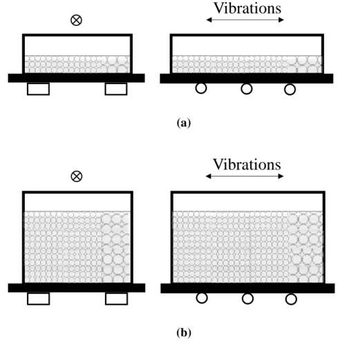
Chapter 3 provides a comprehensive review of the main scientific experimental works on the dynamic behavior of ground-supported circular grain-silos under base excitation and a collection of on-field reconnaissance data on the effects of strong earth motions on real silo structures. First, an insight into the complex behavior of granular material subjected to horizontal shaking is presented before focusing on the behavior of granular material poured inside cylindrical containers in order to better understand the global structural response of grain-silo systems. Then, a review of various experimental tests aimed at investigating the dynamic behavior of ground-supported circular grain-silos performed during the last century is presented. Finally, a review of the most significant cases of structural collapses related to the failures of grain-silo structures due to strong earth motion is chronologically presented.
Chapter 4 collects the main international current code provisions dealing with the structural seismic design of grain-silo structures and draws the actual state-of-the art established in practical and code literature. First, the most salient aspects related to the evaluation of the seismic actions exerted by ensiled bulk content on the silo wall, and the analytical and/or numerical tools applicable to the seismic design of grain-silo structures
are summarized. Then, the main common aspects and the most critical shortcomings individuated among the considered international current code provisions are discussed.
Chapter 5 provides a comparison between the current code provisions and the actual scientific body of knowledge on the static and the seismic behavior of grain-silo structures is presented and the most significant research challenges in the field are summarized
Chapter 6 presents the analytical formulation proposed by Prof. Trombetti and co-workers in 2012 for the evaluation of the horizontal forces produced by grain-like material on the silo wall during earthquake. The problem formulation, the analytical developments and the limits of validity of the proposed analytical formulation are reported. Then, the analytical formulation for the prediction of the shear forces and the bending moments acting on the silo wall are presented. Finally, a comparison of the main analytical findings, in terms of pressures and actions exerted on the silo wall, with those predicted by the classical theories and code provisions is presented.
Chapter 7 presents the shaking-table experimental campaign carried out on silo specimens filled with Ballottini glass carried out at the EQUALS laboratory of the University of Bristol (ASESGRAM project). A full description of the experimental tests is beyond the scope of the present work and has been the objective of a previous Master Thesis (Di Chiacchio 2013). Therefore, only the information necessary for a better understanding of the interpretation of the test results are recalled.
Chapter 8 reports the main experimental results acquired via shaking-table tests and the comparison with the analytical predictions given by the proposed analytical formulation. First, the procedure adopted to reconstruct the experimental bending moment is presented. Then, the influence of the grain-wall friction coefficients on the magnitude of the reconstructed wall base bending moment is presented. Finally, the comparison between the experimental values of the reconstructed wall bending moment and those predicted according to the proposed analytical formulation is performed.
Chapter 9 presents some refinements to the original analytical formulation in 2012. The refinements yield to a significant extension of the theoretical limits of validity and to a new set of analytical formulas for the wall pressures and for the wall shear and bending moment actions. A comparison of the refined analytical formulation with the classical
theories for the static design of grain-silos, the actual code provisions for seismic design of silos and the experimental results described in chapter 8 is also presented.
Chapter 10 presents a novel original analytical formulation for the estimation of the fundamental period of vibration of ground-supported grain-silo systems, starting from the analytical frameworks proposed in chapter 6 and 9. First, the theoretical framework adopted, the basic assumptions and the closed-form expressions for the analytical evaluation of the fundamental period of vibration are presented. Then, the theoretical estimation is compared with the experimental data gathered via shaking-table tests performed within the ASESGRAM project and those available in the scientific literature. Finally, a simple code-like formula and a procedure for the analysis of the dynamic behavior of circular on-ground grain-silos via simplified FE model is also proposed.
Chapter 11 reports the main results of an on-field experimental campaign carried out in the year 2014 on a real operational, horizontally corrugated, vertically stiffened cylindrical steel silo under progressive symmetric filling. Even if beyond the scope of the present thesis, the main aim of such experimental activity is to investigate the structural behavior under static loading of such typology of complex silo structures. This represents a preliminary, first, essential step to be performed in order to get confidence on the peculiar structural response of horizontally corrugated vertically stiffened silos and to develop future experimental investigations focused on the assessment of their dynamic behavior.
Finally, Chapter 12 summarizes the main findings of the previous chapters. Recommendations for future research topics are then provided.
Reference
Di Chiacchio, L. (2013). Interpretation of shaking-table tests of flat-bottom silos containing grain-like material. Master Thesis Dissertation, University of Bologna.
http://amslaurea.unibo.it/5756/
Dogangun, A., Karaca, Z., Durmus, A., & Sezen, H. (2009). Cause of damage and failures in silo structures. Journal of performance of constructed facilities, 23(2), 65-71.
EQE. 1999. “Chichi, Taiwan earthquake of September 21, 1999 M7.6.” An EQE Briefing, http://www.absconsulting.com/resources/ Catastrophe_Reports/Chichi-Taiwan-1999.pdf Jan. 29, 2008.
Fierro, E. A., Miranda, E., Perry, C. L., Lynn, A. C., & Reitherman, R. (2011). Behavior of nonstructural components in recent earthquakes. In Proc. 2011 Architectural Engineering National Conference, Oakland, CA.
Uckan, E., Akbas, B., Shen, J., Wen, R., Turandar, K., & Erdik, M. (2015). Seismic performance of elevated steel silos during Van earthquake, October 23, 2011. Natural Hazards, 75(1), 265-287.
PART A: Updated state of the art
Part A presents a comprehensive review of the main analytical, numerical and experimental researches devoted to the study of the static and dynamic behavior of flat-bottom cylindrical grain-silos, together with a review of the current design code provisions for the seismic design of grain-silo structures. A comparison between the current code provisions on the seismic behavior of flat-bottom grain-silo structures and the actual body of knowledge is provided.
2. Literature review of the analytical and the numerical studies on the dynamics of flat-bottom silos containing grain-like material
In the present chapter, a review of the main analytical and numerical works on the static and the dynamic behavior of ground-supported circular grain-silos proposed in the scientific literature is presented. The main aims of this review activity are to (i) collect and trace the time-evolution of the analytical and numerical studies on the static and the dynamic behavior of grain-silos and (ii) organize, condense, compare and critically discuss the main aspects related to the analytical and numerical works on the static and the dynamic behavior of grain-silos. First, the main analytical studies assessing the static response and the dynamic behavior of grain-silos are discussed. Then, the main numerical studies assessing the static response and the dynamic behavior of grain-silos are discussed.
2.1 Analytical studies
In this section, a review of the analytical formulations on the static and the dynamic behavior of grain-silos is reported. Various analytical models have been proposed in the scientific literature for: (i) the assessment of the actions exerted by the grain on the silo wall under static conditions or under accelerated conditions; (ii) the prediction of the dynamic response of vibration of ground-supported circular grain-silo systems under base excitation. First, among the many analytical formulations proposed in the scientific literature for the prediction of the grain-wall pressures after filling (static conditions), the most significant theoretical studies are presented; then, the theoretical formulations on the dynamic behavior of grain-silo systems under base excitation reported in the scientific literature are presented.
2.1.1. Janssen (1895) (static)
The first analytical model aimed at estimating the actual distribution of the vertical and horizontal pressures on the wall of circular silos containing grain-like material is dated back to the end of the 19th century and was proposed by Janssen (1895).
By means of a continuum approach, the grain-like material is treated as a set of overlapped layers of infinitesimal height dz, where z represents the distance of a single horizontal layer of grain from the free surface. With the purpose of evaluating the effective
mass of grain that leans against the wall and providing conservative design indications for
the static case, the vertical grain-grain pressure at a generic distance z from the grain free surface, referred to as pv
z , is assumed to be equally distributed over the whole cross-section surface A and independent on the radial coordinate x. This assumption leads to an axial-symmetric distribution of the horizontal and vertical forces on the wall. The frictional vertical forces along the grain-wall contact surface are conservatively assumed to be fully exploited following the Coulomb yield criterion:0( ) v( )
p z
p z (1)0( )z GW p z0( )
(2)where p z0( ) is the normal horizontal pressure, λ is the pressure ratio (between horizontal and vertical pressures, invariant with the depth),
0( )z is the vertical frictionalstress and is the grain-wall friction coefficient. Numerical values of GW and λ need GW to be evaluated and punctually defined case by case trough specific laboratory tests.
Assuming a horizontal top surface for the grain and considering the vertical forces equilibrium of an elementary grain layer (differential equation of the first order) gives the following exponential form of the normal horizontal pressure p z0( ) that insists on the silo wall at a generic height z :
2 0( ) 1 2 GW z b R GW R p z e (3)
Where is the specific weight of the ensiled material and R is the radius of the b silo.
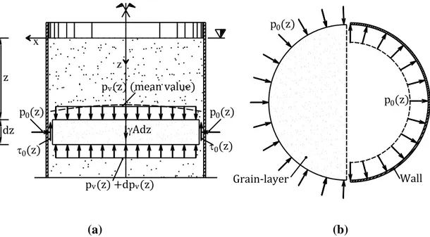
Figure 2.1 shows the pressures distribution acting on the grain and on the wall in static conditions according to the physical idealized model proposed by Janssen (1895).
Later on, Koenen (1986) suggested that the active lateral earth pressure ratio by Rankine (1857) should be used for the prediction of the numerical value of the pressure ratio λ and most of the other theories for silo pressure attempted to find better means of predicting this single quantity (Jaky, 1948; Pieper and Wenzel, 1963; Walker, 1966; Homes, 1972; Walters, 1973; Jenike et al., 1973). Thus, all these Authors adopted the Janssen pressure distribution as basis.
The Janssen’s formula is well consolidated in both the scientific and the practical literature. Experimental evidences reported from tests on small scale models or full scale silos such as those by Prante (1986), Toltz (1903), Jamieson (1903), Lufft (1904), Bovey (1904), Pleissner (1906), Phillips (1910), Ketchum (1919), Amundson (1945), Negi and Norris (1977), Schwab et al. (1994), Vanel et al. (2000), Ovarlez et al. (2003), Tatko and Kobielak (2008) and numerical discrete-particle simulation as those by Rotter et al. (1998), Landry et al. (2003) seem to validate such expression. It usually represents the starting point of any analytical and numerical work concerning grain-silo behavior and widely adopted for the numerical validation of finite element and discrete element models. It is incorporated in most, if not all, silo codes and standards. The adoption of the Janssen formula is suggested for the class of slender silos, where the effect on the grain-wall pressure distribution of the conical pile at the silo top is negligible. The model proposed by Janssen is not straightforward applicable in dynamic (e.g. accelerated) conditions due to the lack of axial-symmetry of the problem.
A translation of the original article by Janssen (1895) is given by Sperl (2006).
(a) (b)
Figure 2.1 - Physical idealized model of Janssen theory (1895) for static conditions. (a) Vertical cross-section. The forces are referred to the grain. (b) Horizontal cross-section. On the left the forces are referred to the grain, on the
right to the wall
2.1.2. Reimbert and Reimbert (1943, 1976) (static)
Reimbert and Reimbert (1943, 1976), starting from the classical Janssen (1895) equation, proposed an alternative semi-empirical solution, which effectively allows to
x z pv(z) +dpv(z) Adz 0(z) p0(z) 0(z)
Janssen & Koenen (1895) theory
dz z p0(z) p0(z) p0(z) pv(z) (mean value) Grain-layer Wall
consider the variation of the value of the parameter (pressure ratio) along the height of the ensiled granular material. In detail, the formulation considers, via a hyperbolic function, that varies between zero at the grain free surface and the value of Rankine active pressure ratio at a great depth. The semi-empirical solution was obtained by curve fitting the experimental results of several tests (conducted on full-scale silos) within the two surface boundaries (free grain surface and silo bottom).
The semi-empirical formulation for the assessment of the normal horizontal pressure p z0( ) that insists on the silo wall at a generic height z results:
2 0 0 ( ) 1 1 2 b GW R z p z z
(4) where 0 2 3 s GW h R z , hs is the height of the superposed conical portion,
starting from the highest grain-wall contact, which value could be calculated as
s r
h R tg , where is the angle of repose of the ensiled granular material. r
Such formulation allows to account for the effect (not directly accounted by the Janssen formulation) of the upper conical portion on the vertical profile and magnitude of the horizontal grain-wall pressure under filling conditions close to the grain free surface. Some comparisons of this solution with Janssen’s formula have been made (Briassoulis 1986, 1987, 1991 and Reimbert and Reimbert 1987), demonstrating the effectiveness of the formulation in case of squat-silos. The formula proposed by Reimbert and Reimbert is currently adopted in its modified version by few standards to determine the static loads during filling for squat and intermediate-slender circular grain-silos, where the effect of the upper conical portion on the vertical distribution of the horizontal grain-wall pressure may be significant.
Many different theories were developed for predicting the static pressures in silos after initial filling and during storage (Airy, 1897; Pieper and Wenzel, 1963; Walker, 1966; Homes, 1972; Walters, 1973; Jenike et al., 1973; Abdel-Sayed et al., 1985), which cannot be exhaustively discussed here. Discussions of these theories and fuller descriptions may be found elsewhere (Arnold et al., 1980; Gaylord and Gaylord, 1984; Abdel Sayed et al., 1985; Bishara, 1985; Ooi and Rotter, 1990; Roberts 1998).
2.1.3. Yang (1976) (dynamic)
Yang (1976) studied the dynamic behavior of cylindrical shell filled with liquid. Even if focused on fluid-liquid storage tanks, this research work provides an analytical framework for the evaluation of dynamic properties (such as fundamental period of vibration and modal shapes) of such cylindrical shell structures. The shell structure is modeled as a cantilever beam. The entire mass of the liquid is considered as a uniformly distributed on the cylindrical shell wall.
2.1.4. Lee (1981) (dynamic)
Lee (1981) proposed an analytical model for the estimation of the mass of the ensiled grain participating with the wall of cylindrical ground-supported silos subjected to harmonic base excitation. In detail, by analyzing the variation of the fundamental frequency of vibration f of grain-silo systems between the empty and the filled condition, the fraction of grain mass participating with the silo wall to the motion (i.e. the effective
mass) is identified. The analytical framework grounds on the following assumptions:
The cylindrical shell deforms only in flexure;
The ensiled granular material does not contribute to the stiffness of the silo wall;
The mass of the system (under different filling conditions) participating to the motion is composed by the wall mass (Mwall) plus the mass added by the
portion of the grain interacting with the silo under dynamic excitation (Madded);
The silo is assumed to behave as a cantilever beam characterized by a uniform distribution of mass, uniform cross-section properties and material, over the whole height of the silo wall;
The vibration mode shape of the grain-silo under dynamic excitation is approximated by the vertical profile of the deformed configuration of the grain-silo system under uniform lateral load.
Starting from the analytical definition of the fundamental frequency of vibration f of a uniform flexural cantilever beam with uniform distributed mass m (using Rayleigh-Ritz method) and considering two different filling configurations, referred to as c1 and c2
(characterized by a corresponding fundamental frequency of vibration fc1 and fc2), the ratio
between the value of the uniform distributed masses m and c1 m results: c2 2 1 2 2 2 1 c c c c f m f m (5)
For any filling configuration, the uniform distributed mass m results as the sum of
the wall mass (Mwall) and the mass added by grain participating with the silo wall to the motion (Madded), divided by the height of the silo wall L, i.e.
wall added
wall addedm M M Lm m . Thus, considering the first filling configuration c1
coincident to the filled configuration, whilst the second filling configuration c2 coincident
with the empty configuration, it simply results that madded mc1mc2 mfilled mempty. Taking into account Eq. (5), after some calculations, the value of the effective mass m , eff
i.e. the ratio between the uniform added mass per unit length madded and the uniform mass per unit length corresponding to the whole mass of ensiled grain-like material mgrain, results: 2 2 1 empty wall filled added eff grain grain f m f m m m m (6)
The values of fundamental frequency of vibration in empty condition fempty and filled condition ffilled have to be experimentally evaluated, and it should be observed that the analytical framework by Lee (1981) retraces that proposed by Chandrasekaran and Saini (1968) and Chandrasekaran and Jain (1968). Although it could be applicable to various filling configurations, because of the assumption of uniform mass distribution along the whole silo wall height L, the application of such analytical model should be applied with reference to such filling configurations that match the aforementioned assumption, i.e. those referred as the empty and the full-filled configurations.
2.1.5. Trahair et al. (1983) (dynamic)
The analytical formulation proposed by Trahair et al. (1983) represents the earliest closed-form prediction of the additional grain-pressure distributions acting on the silo wall
under accelerated conditions. It is developed considering a continuum approach. This formulation grounds on the simplest assumption that each horizontal layer of the ensiled grain applies a load directly to the wall uniformly around the wall circumference. This load is the result of a rigid body motion of the whole ensiled content. This formulation does not consider the load transfer to the base through horizontal grain-grain frictional stresses and ignores the vertical grain-wall frictional stresses (Rotter and Hull, 1989).
These assumptions lead to very simple, conservative, expressions of the radial and circumferential additional pressures (as referred to as pn GW, ( ) and p,GW( ) , respectively) acting on the silo wall in order to balance the inertial forces:
, cos( ) ( ) 2 g b n GW R p (7) , sin( ) ( ) 2 g b GW R p (8)
where g is the ratio of the constant horizontal acceleration to the gravity acceleration g, is the latitude with respect to the direction of the horizontal acceleration and depends on the slenderness ratio of the silo: 1 if H R / 1, ( / )H R for shallower silos. The influence of the grain properties on the overpressure distributions acting on the silo wall is not considered (except for the unit weight, ). Considering that the whole b ensiled content experiences a rigid body motion, the effective mass equals the unity.
2.1.6. Younan and Veletsos (1998) (dynamic)
Younan and Veletsos (1998a) and Veletsos and Younan (1998b) analyzed the dynamic response of vertical, rigid and flexible circular cylindrical tanks filled with a homogeneous, linear viscous-elastic solid medium (Figure 2.2a) under the following basic assumptions: (i) the contained material behaves as a continuous unconstrained cantilever shear-beam (with fundamental circular frequency 1); (ii) the ensiled content with its whole mass dynamically interacts with the circular wall; (iii) no sliding between the contained material and the basement may occur; (iv) two different limit wall-grain interface conditions (ideally rough and ideally smooth) are considered for the circumferential motion in the horizontal plane. The dynamic response of the grain-silo system is characterized by vertical modes (subscript n) and radial modes (subscript m). The