DOTTORATO DI RICERCA IN
Ingegneria Civile, Chimica, Ambientale e dei
Materiali
Ciclo XXIX
Settore Concorsuale di afferenza: 08/B3 Settore Scientifico disciplinare: ICAR/09
TITOLO TESI
The development of a new hysteretic device:
The Crescent Shaped Brace
Presentata da: Antoine Dib
Coordinatore Dottorato
Relatore
Luca Vittuari
Tomaso Trombetti
Correlatore
Stefano Silvestri
“We are all pilgrims who seek Italy”
Johann Wolfgang von GoetheThanks to my parents, I have a life
And thanks to Italy, I know how to enjoy it
ACKNOWLEDGMENTS
The legend says that when God finished his work in the sixth day, he went to relax in his paradise, but he left his shoe somewhere on the earth. The story does not stop here; it continues and says that everyone touches this shoe, may gain magical powers and takes whatever he wants from the paradise.
Being fascinated by this legend since my childhood, I decided to search for the God’s shoe to have the magical powers. But unfortunately, the relation between every legend and every child is destined to fade with time; and my case was not so different. I grow up and I forgot this legend.
Until one day, I received a mail from Dunia-Beam project, congratulating me that I won a full scholarship, three years in Italy, at the Alma Mater Studiorum, to have a PhD degree in civil engineering. And then, after arriving to Italy, I discovered that the legend was not a legend, and the God’s Shoe was not an invention and the magical powers are not a lie. Yes, everything was true; really, I am telling you the truth!!! I discovered that Italy is the God’s Shoe, and that Italians are the fortunate people to touch this shoe and take from the paradise wherever they want: they took the beauty, the art, best artists, best food, best fashion, best life, best nature, best cars…and best engineers!
For this reason, with the text of this thesis completed in my hands, I would like to express my gratitude to every one helped me to believe again in legends: my supervisor, Prof. Tomaso Trombetti, a great person who changed in me the way of seeing the world of engineering with his creativity and authenticity of thinking. I also would like to thank my co-supervisor, Prof. Stefano Silvestri, another great humble person who significantly contributed to the development of this thesis. A big hug is dedicated to my friends and colleagues, with whom I shared a lot of moments: Michele for all his support and help in this thesis, and of course for all the coffee breaks we spent together. How can I forgot all the laughs I had with Simo (who discovered as
the friends I spent with them beautiful moments and had amazing dinners, Spritz and Cotolette.
A big big “thank you” goes to all my friends, who always supported me and helped me to discover myself in parallel with my PhD program. And so, thank you Hiba, Liuba, Christina, Clelia, Pietro, Tim-Noah, Donatella, Davide, Silvia, Alessandro, Wal, Federico, Michelangelo, Olgu, Angela, Sarah... and all the other friends I don’t explicitly mention here.
Final thanks to my family for the absolute confidence in me and the constant support even via calls....
What can I say more? Maybe a final Thumb up!!!
Ah yes, I forgot to tell you that during my childhood, I was fascinated about another legend as well, a man who discovered a secret passage to go and play with Superheroes in Paradise, I hope to find this passage as soon as possible!!!
Bologna, 31/03/2017 Antoine
ABSTRACT
Negli ultimi cinquant’anni, molti studi e ricerche sono stati condotti nell’ambito di sistemi di isolamento sismico, tecnologie innovative di resistenza al terremoto e smorzamenti supplementari, con lo scopo di fornire all’ingegneria strutturale degli strumenti atti ad incrementare notevolmente le prestazioni sismiche delle strutture.
Il “Crescent Shaped Braces” (CSB) è un nuovo dispositivo isteretico in acciaio da introdurre in combinazione diagonale in strutture intelaiate, recentemente proposto dal nostro gruppo di ricerca dell’Università di Bologna nell’ambito del Performance Based Seismic Design.
Contrariamente al convenzionale sistema di controventamento concentrico diagonal, il CSB consente al progettista di scegliere la rigidezza laterale indipendentemente dalla resistenza allo snervamento del dispositivo, grazie alla sua peculiare forma ad-hoc.
Nella presente tesi, viene trattato lo studio del dispositivo CSB. Sono stati sviluppati modelli analitici al fine di descrivere la risposta del sistema a carichi di trazione e compressione, sia nella prima fase elastica che dopo il raggiungimento del limite a snervamento. Al fine di validare i risultati ottenuti dalla modellazione analitica e valutare la capacità del sistema sottoposto a carico ciclico, sono state condotte diverse simulazioni numeriche utilizzando più software di calcolo. Inoltre, sono stati effettuati test sperimentali, consistenti in prove monotone pseudo-statiche e prove cicliche, su tredici dispositivi campioni realizzati in scala con diverse sezioni trasversali. La risposta complessiva sperimentale in termini di rigidezza, resistenza, duttilità e instabilità globale è stata confrontata con i risultati ottenuti dalle analisi analitiche e numeriche. È stato rilevato che il comportamento complessivo del dispositivo CSB, mostrato dalle prove sperimentali, viene colto adeguatamente dal modello analitico sviluppato e che, i software commerciali utilizzati sono sufficientemente adatti a simularne la risposta isteretica.
Dopo aver valutato le capacità strutturali del Crescent Shaped Brace, un nuovo concetto di progetazione sismica è è stato sviluppato nell’ambito del Performance Based Seismic Design e il sistema “enhanced first story”. Esso si basa sulla separazione tra Sistema Resistente Verticale (VRS) e Sistema Resistente Orizzontale (HRS) al fine di ottenere una certa “objective curve” della struttura. Sulla base di questa nuova concezione strutturale, un esempio applicativo di dispositivo HRS è stato studiato con lo scopo di sfruttare i vantaggi offerti dall’uso del CSB come sistema di dissipazione sismica. Infine, sono stati presentati ulteriori utilizzi indicativi del CSB, non solo come elemento dissipativo al livello del primo piano (“enhanced first story” ), ma anche come collegamento orizzontale, rinforzo angolare per giunti trave-colonna ed elementi dissipativi di facciata.
Parole chiave: Crescent Shaped Braces, Nuovi Dispositivi di Dissipazione Isteretica, Performance Based Seismic Design, Sistema Resistente Orizzontale, Nuovo Approccio Sismico, Objective Curve, Curva di Capacità
ABSTRACT
Over the last fifty years, extensive researches have been conducted in the field of seismic isolation systems, innovative earthquake resisting systems and supplemental damping, showing a potential step towards the boosting of the seismic performance of buildings.
The Crescent Shaped Braces (CSB) is a new simple steel hysteretic device, recently proposed by our group of research at the University of Bologna to be used as an enhanced diagonal brace in framed structures, within the Performance Based Seismic Design framework. By making use of CSBs as lateral resisting system and contrarily to the conventional concentric stiff diagonal braces, the CSB allows the practical designer to choose the lateral stiffness independently from the yield strength of the device, due to its peculiar ad-hoc shape.
In the present thesis, a complete study referring to the crescent shaped brace has been presented. Analytical formulas have been developed to describe the behavior of such devices under tensile and compressive loads, in elastic and post-yielding phases. The same device has been studied through extensive numerical simulations to assess the seismic capacity and its response under cyclic loads. As well, the main results of experimental tests conducted on thirteen scaled CSB specimens realized with different cross-sections are presented. Both monotonic pseudo-static tests and cyclic tests have been performed in order to further assess the seismic behavior of such devices. The overall experimental response in terms of stiffness, strength, ductility and global instability is compared with the design formulations and with the results of numerical simulations developed with commercial software. It is shown that the overall experimental behavior of CSB is well captured by the design formulas and that commercial software are suitable to simulate the hysteretic response of such device.
After the validation of the analytical formulas and the hysteretic capacities of the Crescent Shaped Braces, a new seismic concept has been proposed within the
Performance Based Seismic Design and the concept of the enhanced first story. It relies on the total separation between the Vertical Resisting System (VRS) and the Horizontal Resisting System (HRS) in order to attain a certain objective curve of the structure. An applicative example has been studied following this concept and exploiting the advantages of the CSBs as seismic dissipative devices, to be used for the HRS.
Some indicative use of the CSB have been presented, not just as dissipative elements in the level of the first story, as well as horizontal link, angle reinforcement for beam-column joints and façade dissipative elements.
Keywords: Crescent Shaped Braces, New Hysteretic Dissipative Devices, Performance Based Seismic Design, Horizontal Resisting System, New Seismic Approach, Objective Curve, Capacity curve
Table of contents
ACKNOWLEDGMENTS ... v ABSTRACT ... i ABSTRACT ... iii Table of contents ... v List of Figures ... ixList of Tables ... xii
1. Introduction ... 1
1.1. Background and Motivations ... 1
1.2. Problem Description ... 3
1.3. Organization and objectives of the thesis ... 4
PART A: Seismic Philosophies Design and Dissipative Techniques ... 8
2. Seismic Protection of Structures ... 10
2.1. Introduction ... 10
2.2. Traditional Philosophy of a Seismic Design ... 13
2.3. Modern approach through structure control: energy dissipation systems ... 14
2.3.1. Active Control System ... 17
2.3.2. Semi-Active and Hybrid Control System ... 18
2.3.3. Passive Control System ... 19
2.4. Hysteretic Dampers ... 22
2.5. Conclusions ... 25
3. Seismic Design Philosophies and Concepts ... 27
3.1. Introduction ... 27
3.2. Traditional and New Approaches of Seismic Design ... 28
3.2.1. Traditional Method ... 28
3.2.2. Innovative Methods ... 29
3.3. Capacity Spectrum Curve ... 33
3.4. The Proposed Method ... 34
4. The Proposed Method and the Objective Curve ... 39
4.1. The Structural Concept ... 39
4.2. Vertical System ... 41
4.3. Desired Objective Curve ... 44
4.4. Horizontal System ... 44
4.5. CSB Devices To Fulfill The Performance Objectives ... 46
4.6. Conclusions ... 51
PART B: Constitutive Behavior of the Crescent Shaped Brace ... 54
5. Behavior of CSB: Analytical Developments ... 56
5.1. Introduction ... 56
5.2. Geometrical and Mechanical Properties ... 56
5.3. Equilibrium Equations ... 59
5.4. The linear elastic behavior ... 59
5.5. the post elastic behavior ... 62
5.6. Applicative Example ... 63
5.6.1. Behavior under Tensile Loads ... 64
5.6.2. Behavior under Compressive Loads ... 73
5.7. The Double CSB Equations ... 78
5.8. Conclusions ... 79
6. Behavior of CSB: Numerical Simulation ... 81
6.1. Introduction ... 81
6.2. Behaviour under Tensile Loads ... 83
6.3. Behaviour under Compressive Loads ... 84
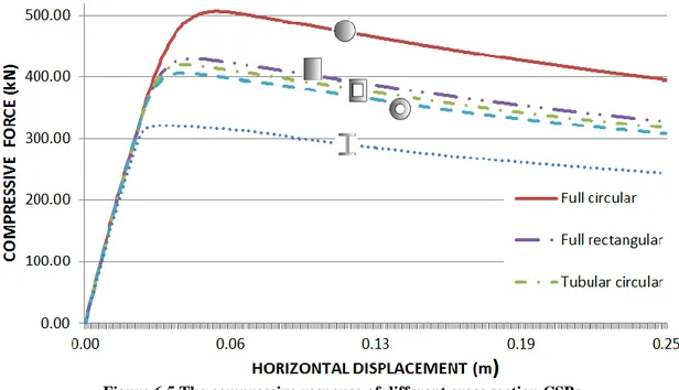
6.4. Influence of The Cross Section ... 86
6.5. Influence of The Coupled CSB ... 88
6.6. Influence of The Double CSB ... 90
6.7. The Material Behavior ... 93
6.8. Conclusions ... 94
7. Behavior of CSB: Experimental Tests ... 97
7.1.2. Test set-up and protocols ... 100
7.1.3. Main goals of the experimental tests ... 107
7.2. The Force – DIsplacement response ... 109
7.3. The Effect of Welding on The Crescent Shaped Brace... 124
7.3.1. Analysis of the tensional state ... 124
7.3.2. Identification of the situation of highest stress and calculation of the maximum stress in the tensile cycle ... 125
7.3.3. Identification of the situation of the highest stress and the calculation of the maximum stress in the compression cycle ... 126
7.3.4. Remarks ... 126
7.4. Assessment of The Ductility Capacity ... 127
7.5. Energy Dissipation Capacity ... 128
7.6. Local Deformations Through The DIC Technique ... 132
7.6.1. The digital image correlation (DIC) ... 132
7.6.2. The deformation fields through the DIC technique ... 134
7.7. Conclusions ... 138
8. Analytical Numerical Experimental Correlation Study ... 141
8.1. The Numerical Results ... 141
8.2. The Force-Displacement Curves ... 142
8.3. The Material Behavior ... 144
8.4. Conclusions ... 146
PART C: Design Solutions and Procedures ... 150
9. Possible Dispositions of The Crescent Shaped Braces ... 152
9.1. The First Soft Story Concept ... 152
9.2. The Strongback or Backbone Concept ... 157
9.3. Other solution (external facades, single disposition, double disposition) ... 160
9.3.1. CSB AS A BEAM-COLUMN JOINT... 161
9.3.2. CSB AS A HORIZONTAL LINK... 161
9.3.3. CSB AS DISSIPATIVE DEVICES ALONG THE STRUCTURE... 162
10. Design Procedure ... 165
10.2.The Proposed Approach and The Concept of the Fisrt Storey Isolation ... 165
10.3.Applicative Example ... 177
10.3.1. Load Analysis ... 180
10.3.2. Numerical Application:... 181
10.4.Conclusions ... 187
11. Conclusions and Future Developments ... 188
11.1.Main Conclusions ... 188
11.2.Future Developments ... 191
Appendix A: Calculation of δ (under flexion) of a system composed of single element with two different inertia. ... 192
List of Figures
Figure 2.1 The seismic energy dissipation concept ... 11
Figure 2.2 Categories of structural seismic protections ... 13
Figure 2.3 Influence of base isolation ... 15
Figure 2.4 Influence of viscous dampers ... 16
Figure 2.5 Active Control System Working Chart ... 17
Figure 2.6 Semi-Active Control System Working Chart ... 18
Figure 2.7 Hybrid Control System Working Chart ... 19
Figure 2.8 Passive Control System Working Chart ... 20
Figure 2.9. A viscous damper inserted inside a residential building ... 21
Figure 2.10 The TMD inserted in the Taipei Tower ... 22
Figure 2.11 An example of a Rotational Friction Damper ... 24
Figure 2.12 Example of Concentrated Dissipative Braces ... 25
Figure 3.1 The Performance Based Seismic Design Objectives ... 31
Figure 3.2 The desired Objective Curve Normalized in terms of Fy and y ... 36
Figure 4.1 An example of a soft or weak first story building ... 41
Figure 4.2 The difference between the VRS capacity curve and the objective curve ... 45
Figure 4.3 The CSB are inserted at the first level based on the concept of enhanced first story .. 47
Figure 4.4 The building designed to verify the PBSD objectives using CSB ... 48
Figure 4.5 The Castel Hill School in Bisignano ... 49
Figure 4.6 The behavior difference between the naked and the equipped structure in X direction ... 50
Figure 4.7 Example of the inserted CSB in X direction ... 50
Figure 4.8 The behavior difference between the naked and the equipped structure in Y direction ... 51
Figure 5.1 A single Crescent Shaped Brace ... 56
Figure 5.2 A single Crescent shaped Brace inserted in a frame ... 57
Figure 5.3 Geometrical characteristics of a CSB device ... 59
Figure 5.4 The stress-strain steel behavior ... 64
Figure 5.5 the deformation of a CSB device under tensile loads ... 65
Figure 5.6 The change of the section characteristics after the yielding point ... 67
Figure 5.7 Analytical response of a rectangular cross section CSB device under tensile loads ... 73
Figure 5.8 The deformation of a CSB device under compression... 74
Figure 5.9 Analytical response of a CSB device under compressive loads ... 78
Figure 5.10 Double CSB devices inserted together ... 78
Figure 5.11 The force acting on one half of one CSB device from a double disposition ... 79
Figure 6.1 The Menegotto-Pinto Model ... 82
Figure 6.2 Force-Displacement curve of a rectangular cross section CSB under tensile loads .... 84
Figure 6.3 Force-Displacement curve of a rectangular CSB under compressive loads ... 85
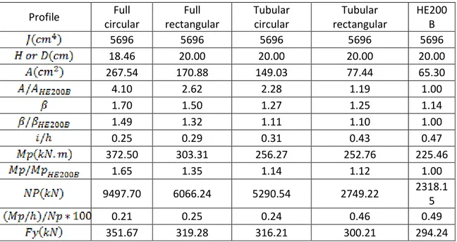
Figure 6.4 The tensile response of different cross section CSBs ... 87
Figure 6.5 The compressive response of different cross section CSBs ... 88
Figure 6.6 A couple CSBs inserted in a generic frame ... 89
Figure 6.7 The behavior force-displacement of coupled CSBs inserted in a generic frame ... 90
Figure 6.8 The Force(kN)-Displacement(m) curve (grey) of a single circular cross section CSB under tensile loads ... 90
Figure 6.9 The Force-Displacement curve (grey) of a double circular cross section CSB under
tensile loads ... 91
Figure 6.10 The Force(kN)-Displacement(m) curve (grey) of a single circular cross section CSB under compressive loads ... 92
Figure 6.11 The Force(kN)-Displacement(m) curve (grey) of a double circular cross section CSB under compressive loads ... 92
Figure 6.12 The material response under cyclic loading (ABAQUS) ... 93
Figure 7.1 Six Specimens (rectangular and circular cross section) before testing with ends details ... 99
Figure 7.2 RW1R, RR1R, TW1R before testing with welding details ... 100
Figure 7.3 The universal traction machine ... 101
Figure 7.4 Details of the bolts used at the extremities... 101
Figure 7.5 The typical loading protocols: left) traction, middle) compression, right) reversed .. 104
Figure 7.6 RR2R, RW2R, RW3R and TW2R before testing ... 108
Figure 7.7 RW2R inserted in the test machine during the test loading ... 108
Figure 7.8 The adopted measures for the rectangular cross section specimens ... 109
Figure 7.9 The force-displacement response of R1T ... 110
Figure 7.10 The force-displacement response of R2C ... 111
Figure 7.11 The force-displacement response of R3R ... 111
Figure 7.12 The applied dimensions for circular cross section specimens ... 112
Figure 7.13 The force-displacement response of C1T ... 113
Figure 7.14 The ovalisation of the bolt hole ... 114
Figure 7.15 The force-displacement response of C2C ... 114
Figure 7.16 The force-displacement response of C3R ... 115
Figure 7.17 The applied geometry of the welded rectangular cross section specimens ... 116
Figure 7.18 The force-displacement response of RW1(C+T) ... 117
Figure 7.19 The force-displacement response of RW2R ... 118
Figure 7.20 The force-displacement response of RW3R ... 119
Figure 7.21 The applied geometry for the rectangular cross section with ribs specimens ... 119
Figure 7.22 The force-displacement response of RR1R... 120
Figure 7.23 The force-displacement response of RR2R... 121
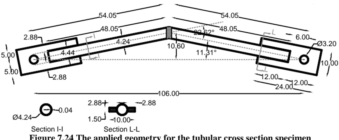
Figure 7.24 The applied geometry for the tubular cross section specimen ... 122
Figure 7.25 The force-displacement response of TW1R ... 123
Figure 7.26 The force-displacement response of TW2R ... 123
Figure 7.27 The RW1 before being welded ... 124
Figure 7.28 Ductility capacity of the R3R specimen left) in tension, Right) in compression ... 128
Figure 7.29 Ductility capacity of the C3R specimen left) in tension, Right) in compression ... 128
Figure 7.30 R3R equivalent damping ratio Left) Tension; Right) Compression ... 129
Figure 7.31 C3R equivalent damping ratio Left) Tension; Right) Compression ... 130
Figure 7.32 RR1R equivalent damping ratio Left) Tension; right) Compression ... 130
Figure 7.33 RW2R equivalent damping ratio Left) Tension; Right) Compression ... 131
Figure 7.34 TW2R equivalent damping ratio Left) Tension; Right) Compression... 131
Figure 7.35 Basic concept of the image correlation ... 133
Figure 7.36 R3R and RW1R colored to be tested by the DIC technique ... 134
Figure 7.37 The results by the DIC technique of the RW1R specimen ... 134 Figure 7.38 The correspondent DIC technique results to the force-displacement behavior curve of
Figure 7.39 The correspondent DIC technique results to the force-displacement behavior curve of
the specimen C2C ... 136
Figure 7.40 The material behavior of the C3R specimen under reversed test ... 137
Figure 8.1 The force-displacement curve under tensile loads ... 143
Figure 8.2 The force-displacement curve under compressive loads ... 144
Figure 8.3 Comparison between numerical and real material behavior ... 145
Figure 8.4 Comparison between numerical and real material behavior ... 146
Figure 9.1 Possible dispositions of the CSB: from left to right: first story isolation, Diagonal dissipative elements, double diagonal dissipative elements, and horizontal links ... 152
Figure 9.2 An example of a residential building with a weak first story ... 153
Figure 9.3 The above residential building idealized as a SDOF with the mass of the upper-structure m ... 153
Figure 9.4 The proposed approach is the combination of the Fintel & khan concept and the PBSD ... 155
Figure 9.5 The idealization of a building as a simple oscillator or SDOF ... 155
Figure 9.6 Difference between the response of a backbone and soft first story structures ... 158
Figure 9.7 Different backbone structures types ... 158
Figure 9.8 Crescent Shaped Brace Element can be used as horizontal link or angle reinforcement ... 161
Figure 9.9 VIII Agosto Building in Bologna City ... 162
Figure 9.10 single coupled CSBs inserted in VIII Agosto building ... 163
Figure 9.11 A double coupled CSB devices inserted in a frame as a Pall Friction Damper ... 163
Figure 9.12 VIII Agosto enhance by double CSB devices ... 164
Figure 10.1 The SDOF idealization of the ‘enhanced first story” isolated structure ... 166
Figure 10.2 The objective curve in terms of stiffness, strength ductility and earthquake levels 168 Figure 10.3 The different resisting systems of the proposed approach ... 173
Figure 10.4 CSB inserted in a frame ... 174
Figure 10.5 Coupled CSB inserted in an ‘enhanced first-story’ building ... 175
Figure 10.6 Flow-chart of the proposed procedure ... 176
Figure 10.7 Plan and Facades of the first floor of the studied example ... 178
Figure 10.8 Plan Details ... 179
Figure 10.9 VRS Capacity curve ... 181
Figure 10.10 The objective curve (black), VRS capacity curve (Red) and the HRS capacity curve (Blue) ... 184
Figure 10.11 the total response F-d of a couple of CSB, one is stretched under tensile loads, the other is compressed under compressive loads (cross section HE240B, d/L=0.1) ... 185
Figure 10.12 Capacity curve of the Horizontal Resisting System (HRS) composed of four couples of Crescent shaped Braces stretched/compressed in every direction ... 186
List of Tables
Table 5-1 i/h of typical steel profiles ... 58
Table 5-2 Deformation values under elastic tensile loads ... 65
Table 5-3 Deformation values under elastic tensile loads (second method) ... 66
Table 5-4 Deformation values of CSB device under post-elastic tensile loads... 71
Table 5-5 Deformation values of CSB device under plastic tensile loads ... 71
Table 5-6 The values of the hardening response of a (4.14x1.5 cm) CSB devcice ... 72
Table 5-7 Deformations value of a CSB device udner elastic compressive loads ... 76
Table 5-8 Deformation values of a CSB device under post-elastic compressive loads ... 77
Table 6-1 Geometrical and mechaniccal properties of the studied profiles ... 86
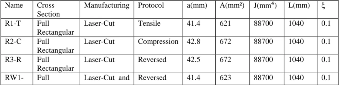
Table 7-1 Geometrical properties of the studied specimens ... 99
Table 7-2 The applied protocol at the R1T specimen ... 104
Table 7-3 The applied protocol at the R2C specimen ... 104
Table 7-4 The applied protocol at the R3R specimen ... 105
Table 7-5 The applied protocol at the C1T specimen ... 105
Table 7-6 The applied protocol at the C2C specimen ... 105
Table 7-7 The applied protocol at the C3R specimen ... 105
Table 7-8 The applied protocol at the RW1(C+T) specimen ... 106
Table 7-9 The applied protocol at the RW2R specimen ... 106
Table 7-10 The applied protocol at the RW3R specimen ... 106
Table 7-11 The applied protocol at the RR1R specimen... 106
Table 7-12 The applied protocol at the RR2R specimen... 107
Table 7-13 The applied protocol at the TW1R specimen ... 107
Table 7-14 The applied protocol at the TW2R specimen ... 107
Table 8-1 Comparison between analytical and experimental numerical results ... 142
Table 10-1 the performance objectives ... 168
1. Introduction
1.1. BACKGROUND AND MOTIVATIONS
Life after an earthquake is definitely different than life before it: losses of lives, parents, friends, houses, properties… are sufficient to change way of life and print it with bad memories… Thus, the society trust engineers to build them facilities like houses, roads, offices, hospitals, theatres, dams… in a way that can afford a disaster like earthquakes and remain afterward functional without any loss.
Regarding numbers, the problem of earthquakes is not the live losses anymore, an average of 10,000 people die each year from earthquakes compared to 1,300,000 deaths by car accidents.
Looking to the number of death on the Italian territory for the last 20 years due to earthquakes, which is around 687 death (309 due to the L’Aquilla earthquake 2009 and 295 under the Amatrice Earthquake 2016), with an average of 35 death per year, it is evident that this number is less than the number of victims of car accidents for example in the same country, which is 3753 just for the year 2013.
In japan for example, the number of deaths due to earthquakes in last 20 years is around 16022 deaths (15894 due to 2011 Earthquake, one of the biggest worldwide earthquakes) with an average of 801 deaths per year in front of 5971 deaths by car accident for the year 2013.
The real problem is the changes induced after a ground motion, the number of deaths after just one event and the collapse of buildings, apartments and even full villages. These changes cost the government/ civil communities a big amount of money. For example a UNESCO study gives damage losses amounting to $10,000,000,000 from 1926 to 1950 due to earthquakes.
Putting a part that a big number of earthquake deaths are not related directly to structural failure but as well to fire, weather climate, nonstructural collapse… the old idea behind the structural seismic design that life safety is the goal of engineers and
society, is an under estimate goal of design and the new philosophies of design are more ambitious than the old concept. [31], [68], [80]
Thus, it is not strange to say that structural dynamics is the topic of the 21st century. It took almost the entire 20th century to bring the civil structural engineering profession to the point where buildings and other structures can be analyzed with a reasonable degree of confidence to evaluate their performance to real civil engineering types of forcing functions. The first part of the 20th century was primarily devoted to developing a basic theoretical foundation that incorporated the principles of mathematics and mechanics using very simple idealizations of structures. The result was that starting from the 1960s, structural analysis moved onto a much more sophisticated and accurate phase where it incorporated the mathematics of matrix methods and numerical analysis to develop analytical models of structures. This led to modern finite element methods of structural analysis using high-speed digital computers.
Recently, the Performance Based Seismic Design has been proposed as the most upto -date methodology to predict the response of any structure under different types of ground motion, from fully operational response under frequent earthquakes to near collapse response under rare ones. [14], [17], [67]
In order to design a structure to withstand different levels of earthquakes, the correspondent actions acting on it must be specified. The amplitudes of the possible actions that will occur during the life of the structure cannot be known in a deterministic way. Thus a reliable estimation of their maximum expected values is important, since the cost of construction, and therefore the economic viability of the project depends on a safe and cost efficient final product. [13], [14],[49], [65]
Factors such as the dynamic characteristics of earthquakes, their duration and the effects of site conditions are all external to a building. No matter how well or poorly designed, a building has no control over those effects. A combination of factors such as the structural configuration of a building, its materials of construction and dynamic characteristics, as well as the quality of its structural design and construction, greatly influence how a building responds to any shaking it experiences. Therefore, it is better
to turn the attention to those aspects of a building itself that largely determine its seismic response.[14]
To have more precise idea about these forces, many procedures where developed to know the seismic forces: for regular building, an Equivalent Static Force method has been developed; for irregular buildings, Dynamic analyses are used. [13], [17], [30], [42]
Conventionally designed and constructed, earthquake-resistant buildings rely on significant inelastic actions or energy dissipation in selected components of the framing system in the design earthquake. For common used moment-resisting frames, inelastic action should occur in the beams near the columns and in the beam-column panel zones: both zones form part of the gravity-load-resisting system. Inelastic actions results in damage, which is often substantial in scope and difficult to repair. Damage to gravity-load-resisting system can result in significant direct and indirect (business interruption) losses. [31], [42],
The desire to avoid damage to components of gravity-load-resisting frames in buildings leads to add energy dissipation systems, to build frames focusing the energy dissipation during an earthquake into those disposable elements specifically designed for this purpose and to substantially reduce energy dissipation in the gravity-load-resisting frame. As energy dissipators do not form part of the gravity frame and can be replaced after an earthquake without compromising the structural integrity of the frame, passive metallic yielding, viscoelastic and viscous energy dissipators are now available in the marketplace.
1.2. PROBLEM DESCRIPTION
Not just researches aim was to describe mathematically the seismic behavior of any structure, but it was devoted to find solutions to the stability of the structure under any ground motion. Even though, many design philosophies have been proposed since modern Earthquake Engineering has been established in the 1960, they can be generally classified as traditional or innovative solutions. While traditional solutions mainly relies upon strength, stiffness and ductility capacities of frames, bracings and
walls, more innovative solutions are based on the use of energy dissipation devices or base isolation devices which absorb/ reduce the input energy which is transmitted to the structure by the earthquake ground motion.[13], [43], [49], [51],
Seismic Dampers are one among the solutions and they are used in place of structural elements, like diagonal braces, for controlling seismic damage in structures. They partly absorb the seismic energy and reduce the motion of buildings.
One of the design strategies allowing the achievement of multiple performance objectives is based on the conceptual separation of the vertical resisting system from the horizontal resisting system. Clearly, in order to design a structure behaving closely to the desired “objective curve” [49], the lateral resisting system must be conceived in order to be very flexible in terms of its stiffness, strength and ductility. In the recent years, researches have been focused on enhanced bracing systems, one of them, is the Crescent Shaped Braces, studied in this thesis. This device, thanks to its peculiar shape, allows design its lateral stiffness independently from its initial yield strength thus appearing suitable to be used for an enhanced lateral resisting system. Not just the independency between stiffness and strength is the only characteristic of the Crescent shaped Brace, the ductility which presents, and the last hardening behavior which avoid collapse under P-Delta effect, altogether form a good point for this device to be inserted in buildings, giving engineers a lot of independents parameters to play with.[26], [27], [55], [56], [64]
In the present thesis, the results of the experimental tests performed on scaled prototypes are presented and compared with analytical and numerical predictions, developed formerly and finishes with some examples of how the device can be inserted in a real building and all its possible dispositions.
1.3. ORGANIZATION AND OBJECTIVES OF THE THESIS
The thesis is organized in three parts: part A, part B and part C. Part A focuses on energy dissipation systems in the field of seismic engineering and is composed of three chapters: chapter 2 , chapter 3 and chapter 4. Part B is devoted to the study of on a new hysteretic dissipative device, the Crescent shaped Brace (CSB), and shows analytically
behavior and an overall comparison between the three results of the previous chapters (chapter 8), part C tries, through its two chapters (chapter 9 and chapter 10) to show some possible implementation of the CSB in real building cases.
The objective of part A is to have an overview above the field of seismic engineering dissipative elements, the development of seismic concepts and philosophies that are behind the Crescent Shaped Brace and a proposal of a new method of design based on the recent researches in the field of seismic engineering which push our team of research to develop this new device.
In details, chapter 2 presents a quick view over the earthquake resistance methods in seismic engineering world, from passive to active, semi active and other classical solutions. In details, passive devices and especially hysteretic ones are more investigated because the studied element in this thesis, the Crescent Shaped Brace, is classified under this category of devices.
Chapter 3 is a general presentation of the seismic design philosophies existing in the engineering world, traditional method which is the Force Based Design (FBD) and new ones like the Performance Based Seismic Design (PBSD) and the Direct Displacement Based Design (DDBD). Referring to the philosophy of the Performance Based Seismic Design, we proposed a new method to be admitted for structural design combining the objectives target of the PBSD and the capacity curve of the structure.
Chapter 4 explains in detail how it is possible to reach our new proposed method, separating between vertical resistant system and horizontal resisting system, where the last one can be reached by inserting special types of devices, as the Crescent Shaped Brace. An ultimate paragraph will be dedicated to show that those new elements, that we are going to study in part B, are able to fulfill the imposed seismic objectives showing previous studies done in the academic world.
The objective of part B is to assess the constitutive behavior of the Crescent Shaped Brace as well as its seismic and dissipative performances through analytical studies, numerical models and experimental campaigns.
Chapter 5 presents the analytical studies developed to understand the behavior of the new hysteretic device under imposed forces. It describes in detail its geometrical and
mechanical properties, the linear elastic and the post yielding behaviors, and trying to describe as well the softening and hardening responses.
Chapter 6 is a numerical study of the crescent shaped brace device both under tensile and compressive loads. The linear elastic and post elastic fields are described using SeismoStruct program. The influence of the cross section and of the inclination of the element has been studied in a second phase. The behavior of a simple crescent shaped brace, double elements and coupled ones are studied in details which can be useful for part C and the applicative example.
Chapter 7 presents a large experimental campaign carried out on 13 specimens in four different phases between 2014 and 2016. Through the experimental campaign, cyclic tensile, cyclic compressive and cyclic reversed tests are assessed on different types of cross sections: fully rectangular, fully rectangular with ribs, fully circular, tubular and welded fully rectangular cross sections. The chapter provides an interpretation of the experimental results and the force displacement behavior obtained from the tests. Ductility and energy dissipation capacities are studied and local deformations are investigated through the DIC technique.
Part B finishes with chapter 8 which is a comparison between the results of the previous chapter. In this chapter, it is clearly explained that the analytical equations developed in chapter 5 do not describe exactly the plastic behavior of the element, while numerical models can described pretty good even they do not take in consideration the imperfection of the specimens. However, the whole results are really close one to each other and can describe clearly the new device.
Part C is the applicative part of the crescent shaped brace. It shows many possible displacements of the element into an existing or new building.
It starts with chapter 9, which shows how this element can be inserted in a real building. It can be inserted as horizontal resistant system in a first soft story structure, or it can be inserted as horizontal link between two different structures for seismic motives.
Chapters 10 contain the applicative example to show, in practice, how the design should be carried out using the crescent shaped braces as passive hysteretic dissipative
corresponding steps are described, so that the entire numerical hypothesis are explained and justified. Then, the studied example is presented and the retrofit intervention is designed based on the concept admitted. The results of the analyses performed on the model of the original structure are presented. In chapter 10, the soft story concept, proposed by Fintel and khan, was the main idea of the retrofitting, thus the flexible crescent shaped braces are used just in the ground floor while the upper structure is stiffened by concentrated braces.
Finally, Chapter 11 summarizes the main findings of the previous chapters. Recommendations for future research topics are as well provided.
PART A: Seismic Philosophies Design and
Dissipative Techniques
Part A is a general introduction to introduce a new hysteretic dissipative device, the Crescent Shaped Brace (CSB) developed in part B and to a new design procedure introduced later in part C. To frame the CSB device, chapter 2 has the role to explain all possible energy dissipation techniques available now in the market of the seismic engineering with a special attention to the category of passive dissipative devices and hystertic ones to which the CSB belongs.
Instead, chapter 3 is a brief review of the traditional and new seismic concepts used by designer to make there seismic decisions. At the end of this chapter, we proposed a new method to be used for seismic calculation. Chapter 4 develops conceptually this method based on a total separation between Horizontal resisting system and Vertical resisting system. This chapter ends with some examples of structures that were enhanced by CSB.
2. Seismic Protection of Structures
2.1. INTRODUCTION
While designing a structure to withstand an earthquake force, it is important to know the forces value acting on it in order to design properly the resisting elements. However, this knowledge is not easy because it depends on many factors: earthquake size, energy transmitted to the structure, distance of the fault to the structure, geological factors, even the structure itself...[4], [14], [15]
The main idea behind any seismic design is to know the amount of energy imparted into a structure during an earthquake ground motions, to design the structure in a way to handle this energy without or with the less possible damages and finally to construct the structure respecting the corresponding design.[1], [4], [14]
The investment in constructed facilities includes many components in addition to the structure. In fact, in most applications the cost of the structure is less than one fourth of the cost of the total investment (depend on way of life), and in industrial facilities this ratio may be even less. However, the survival of the entire investment depends on the survival of the structure. That is why the structural engineer has a critical responsibility and needs to be well informed about the behavior of the structure. [47], [52]
Thus, the seismic design of structures cannot be developed ignoring the energy approach of the design issue.
The load action of dynamic type introduces into a structural system certain amount of energy. The input energy is converted into stored energy and dissipated energy.
EI ≤ ES + ED
The energy ES is stored in two distinct ways:
ES = EE + EK
- EE is the elastic strain energy
- EK is the kinetic energy
Regarding the energy dissipated ED, the dissipation occurs through two different
- EH is the energy dissipated by hysteretic or plastic deformation (associated with
strength that depend only on the deformation)
- EV is the energy dissipated through viscous damping
In few worlds, it is possible to divide those energies into two types, reversible which includes the elastic and viscous energies, and irreversible which corresponds to the kinetic and hysteretic energies.
EI ≤ EE +EV+ EK+EH
Figure 2.1 The seismic energy dissipation concept
The reduction of the horizontal seismic response, independently on the type of the structures or the materials used, and without counting all possible techniques, can be reached using one of those two isolation strategies or by combining them:
1- Increasing the relative period of the construction, taking it to the zone of small acceleration response (damping system)
Decrease with base isolation Increase with chock transmitters Increase with steel hysteretic dampers Increase with viscous dampers Reversibile Irreversible
2- Limiting the maximum horizontal force occurred (base isolation…), [2], [3], [14], [17], [22]
The presence of the dissipation energy, for the same amount of input energy, means that less elastic stresses are applied on the structure with linear elastic behavior.
The traditional building systems (Reinforced concrete, steel structure, masonry building…) rely on ductility to reduce the seismic action to SLU entities.
Substantially, the ductility allows reducing the effects of the earthquake energy through the dissipated energy in form of damage, properly studied, into the structural and non-structural elements.[17], [22], [76], [77],
The innovative seismic designs pursue the reduction of the effects of the earthquake without counting on the energy dissipation which arises from damage of structural and non-structural elements. They rather provide the insertion of devices suitably designed to dissipate the input energy input preserving like this the structure. [17]
The use of a system properly designed to resist seismic actions introduces a new problem, explicitly the need of providing within the structures a double-resistant systems.
Instead of adjusting the structural system to withstand the vertical loads, together with the seismic forces, it is getting the idea to insert a specific resistant system for the horizontal actions which are integrated in parallel with those for the vertical actions. [35]
In general, it is possible to define two areas where the isolation system is active:
The infrastructure, it is the part of the building including the foundations where in general the horizontal deformability is negligible and the upper-structure.
After centuries where traditional ways of dissipation through plastic hinges and damages were by default the only existing techniques of energy degeneracy, many technical means are been developed for the energy absorption of the earthquake: base isolation, thus the energy is absorbed on the level of the foundation, the soft first storey concept idealized by Fintel and khan, so the energy is absorbed by the first shock
absorbing soft storey and the isolation systems: like dampers, passive, active and semi active devices…[71], [76]
Figure 2.2 Categories of structural seismic protections
2.2. TRADITIONAL PHILOSOPHY OF A SEISMIC DESIGN
The traditional seismic design philosophy is based on energy dissipation through inelastic but stable mechanisms. These mechanisms can be accomplished through axial tension-yielding compression-buckling of brace elements, through flexural hinging of columns, walls and beams, and through shear hinging of steel elements. The energy dissipated through those mechanisms can lead to a good seismic performance, if proper capacity design principles are enforced. To notice that the hysteretic energy used to dissipate the seismic input energy in these systems corresponds directly to structural (and non-structural) damage, and is accepted as long as the structure is able to carry the gravity load and its vertical capacity is not jeopardized. [17]
Moment resisting frames are favored for their earthquake resistance capability because properly detailed frames have stable ductile behavior under repeated reversing loads. However, they are very flexible and it is often economically difficult to develop enough stiffness to control storey-drifts and deflections to present non-structural damage.
It is worth to give one example of traditional technique of seismic design to add rigidity to the moment resisting frames: the concrete shear walls. This technique as any technique has its own advantages and disadvantages.
The main advantages can be summarized as follow: the concrete is a low cost and effective building material, especially for wall construction. Concrete walls can be detailed with boundary elements and field steel for reliable, ductile cyclic response. Due to the high stiffness of concrete shear walls, the expected inelastic drifts should decrease for a structure designed to have such elements. [14]
In general, any advantage gained by added stiffness is negated by the increased amount of energy input, and thus place higher demand on strength and ductility which is sensitive in reinforced concrete to detailing and quality control.[17]
Regarding other disadvantages, from structural point of view, shear walls located at the core would develop a large overturning moments in narrow elements, which lead to high uplift forces and hence expensive foundations. As well, if walls would be clustered around the center of the floor plate (usually near elevators), this leads to torsional flexibility of the building, and large drifts from accidental mass eccentricity. To not forget that once located, they have to continue from top to foundation. It can be not a suitable solution for existing and fully operational buildings. [14], [17]
Another conventional construction method is the braced steel frames known to be economical and effective in controlling lateral deflections under wind and moderate earthquakes. Instead, during a major ground motion, the performance of these structures is poor. Being stiffer, they invite higher lateral inertial forces and the energy dissipation capacity of the brace is very limited. [17]
2.3. MODERN APPROACH THROUGH STRUCTURE CONTROL:
ENERGY DISSIPATION SYSTEMS
During an earthquake, high energy is applied on the structure. Once applied, the energy is absorbed by the structure or amortized by other devices. If the structure is free of damping (traditional philosophy), its vibration will be continuously, but due to the
structures progression pursues the reduction of the effects of the earthquake without counting on the damage of structural and non-structural elements. They rather provide the insertion of devices suitably designed to dissipate the input energy. Lateral force reduction can be achieved by inserting special devices under the structure like base isolation or by the use of dampers. [17], [33], [36], [66]
Damping reduces structural response (acceleration and displacement): damping effect at high periods is not counted on spectrum amount; as well as at low periods, it has low effect on response acceleration. Figure 2.3and Figure 2.4 show the effect of damping increasing in the periods from 0.3 to 2.5 seconds.
Among the advantages of using dampers we can infer to high energy absorbance, easy to install and replace them not counting the coordination to other structure members.
Figure 2.3 Influence of base isolation
Figure 2.4 Influence of viscous dampers
Damping system is the collection of structural elements that includes all the individual damping devices, all structural elements or bracing required to transfer forces from damping devices to the base of the structure, and the structural elements required to transfer forces from damping devices to the seismic force-resisting system.[17]
In both cases, the isolation performance can be improved, by dissipating through the isolation system, the mechanical energy transmitted from the ground level to the construction.
Damping device is a flexible structural element of the damping system that dissipates energy due to relative motion of each end of the device. They include all pins, bolts, gusset plates, brace extensions, and other components required to connect damping devices to the other elements of the structure. Damping devices may be classified as either displacement-dependent or velocity-dependent, or a combination thereof, and may be configured to act in either a linear or nonlinear manner. [14], [15], [17], [33], [37], [59]
In this section, referring to Figure 2.2, supplemental damping system will be discussed. Thus, active, semi-active, hybrid and passive control systems will be presented and some overview of each technique will be given.
2.3.1. Active Control System
Active vibration control uses some kind of sensor to measure the motion or force or acceleration etc. of the structure and a powered actuator to generate a force to resist the unwanted motion. There is also some kind of logic that controls the actuator so it pushes in the right direction at the right time to reduce the unwanted action.[17]
Typically, an active control system is composed of three integrated components: i) a monitoring system that is able to sense the state of the structure and to record the associated data through an electronic data acquisition system; ii) a control system that receives the data from the monitoring system and decides on the countermeasures to be applied and iii) an actuating system that physically applies these countermeasures to the structure. Therefore, active systems require a continuous external power source to operate properly (Haysami et al)).[17]
Figure 2.5 Active Control System Working Chart
This dependence on external power sources has been a significant limitation on the seismic application of active systems. During a strong earthquake, the electric
transmission and distribution systems can fail. Even backup electrical generating systems can be damaged. Furthermore, the control algorithm may become unstable during strong seismic shaking and/or operating conditions. These concerns have limited the implementation of active and semi-active systems for seismic control of civil engineering structures worldwide. Japan is the only exception where active systems have been implemented in several buildings. [17],
2.3.2. Semi-Active and Hybrid Control System
Semi-active systems are in the same category as active systems except that they require a relatively small amount of external energy without the need for a global monitoring system. The control is limited to modifying the local properties of the dampers, such as the geometry of the orifices in a fluid damper, which eliminates the possibility of instability. Because of this low dependence on external power sources and the removal of instability concerns, research on semi-active systems has intensified in recent years. These systems, however, have not yet enjoyed widespread applications in North America and Europe. [17]
Figure 2.7 Hybrid Control System Working Chart
The term of hybrid control systems is used for a hybrid using of active and passive control systems. Semi-active systems are extracted from active control systems. In these cases, the required output energy is lower than active control system. And it is only the producer of electric pulse to provide control system. Semi active control components dose not add mechanical additional energy to structure system (which includes structural and stimulus control), so the stability of input and output connections are guaranteed. Semi-active control components often can be seen as passive control components. Particularly, more resistant or depreciate forces are produced by internal mechanism based on feedback output sensor. So the combination ability of the best active and passive systems or against less reduction of desired components and due to low power, have high control ability. Semi-active systems are an attractive alternative for active and hybrid systems.[17], [26], [71]
2.3.3. Passive Control System
Passive systems, on the other hand, as their name indicates, operate without external computers, power supply or actuators. As it shown in Figure 2.8, “passive systems have properties that cannot be modified during the seismic response of the structure.” Once they are implanted into a structure, the seismic input energy contained in a narrow
frequency band is dissipated through the fixed characteristics of the passive dampers shown to be effective, robust and economical solutions. “The implementation of passive systems has outdistanced significantly the implementation of active systems.”[17], [23]
Maybe one impediment to the widespread use of passive energy dissipation systems have been the lack of robust and validated guidelines for the modeling, analysis, design and testing of the dampers. [10]
Figure 2.8 Passive Control System Working Chart
Passive energy dissipating systems can be divided into three different categories: displacement-activated devices, velocity-activated devices, and motion-activated devices. Note that some systems, such as viscoelastic dampers, can be classified both as displacement and velocity-activated device. [44], [50], [61]
Displacement-activated devices are characterized that their force response is primarily a function of the relative displacement between each end of the device, in another words the relative displacements occur simultaneously with the maximum internal forces. The response is substantially independent of the relative velocity between each of the devices and/ or the excitation frequency. Typical dampers falling in this category include metallic dampers, friction dampers and self-centering dampers.[17], [24]
Velocity-activated devices dissipate energy through the relative velocities that occur between their connected points. The force-displacement response of these dampers usually depends on the frequency of the motion. Also, the forces generated by these devices in the structure are usually out-of-phase with the internal forces resulting from shaking. Therefore, the maximum forces generated by the dampers do not occur simultaneously with the maximum internal forces corresponding to the peak transient
members where the devices installed as well as in lower design forces for the foundations. Typical dampers falling in this category include purely viscous and visco-elastic dampers. [17], [41]
Figure 2.9. A viscous damper inserted inside a residential building
A motion-activated device disturbs the flow of energy in the structure through the vibration of a secondary system. Tuned-Mass Dampers (TMDs) are examples of motion-activated devices. A TMD is a relatively small secondary mass-spring-dashpot system that is attached to a structure in order to reduce its dynamic response. The secondary system is tuned to be in resonance with the main structure on which it is installed. Under a dynamic excitation, the TMD resonates at the same frequency as the main structure but out-of-phase from it, thereby diverting the input energy from the main structure into itself. The input energy is dissipated by the inertia forces applied by the TMD on the main structure. These systems, usually installed on the roofs of buildings, have been proven effective in reducing wind-induced vibrations in high-rise buildings and floor vibrations induced by occupant activity (Haysami et al).[12], [17], [53], [54]
For example, inside Taipei World Financial Center in Taiwan is the largest and heaviest regulated damper (TMD) which is installed globally. And they act as a big pendulum, a big steel core that is moved slowly in front and rear of each movement of building. This is an engineering feat and is able to limit the vibration of a tall building above 500 meter. A steel core with 5.5 m diameter and 728 tons weight are suspended with 8 cables from the top floors of the tower. And they are visible between floors 88 and 92. And it is one of the tallest structures in the world which are located about 200 meters from main fault line and wind and earthquake are serious problems for this
structure. In fact, tourists could even take photos from this TMD during Sishan earthquake. (Haysami et al)
Figure 2.10 The TMD inserted in the Taipei Tower
In this 101-story towers, this steel core able to bear 1.5 meter movement in each direction. And they reduce the vibration range about 30 to 40%.
2.4. HYSTERETIC DAMPERS
One of the most efficient dissipation mechanisms of the energy transmitted to structures through earthquakes is one that takes advantage of the plastic deformability of the metal elements, from here born the idea of entrusting the seismic energy dissipation devices able to undergo large plastic deformation cycles, and then dissipate to hysteresis a high amount of energy. [17]
Some of the hysteretic devices that have demonstrated a particularly desirable behavior are here briefly recalled. The Added Damping – Added Stiffness (ADAS) device, originally manufactured by Bechtel Corporation in the 1980s, is usually installed between the apex of a chevron brace and the underside of the beam. The Triangular Added Damping – Added Stiffness (TADAS) device is a variation of the original ADAS device which makes use of triangular plates as dissipative steel elements. In the mid-1970s, Lead Extrusion Devices (LED) were proposed in New Zeland (Robinson and Greenbank 1976) taking advantage of the stable and repeatable hysteretic behavior
manufactured by Nippon Steel Corporation in the early 1980s, consists in a steel member encased in a tube filled with concrete that prevents the buckling.
Even if the market is full of different types of hysteretic devices, all of them are intended to provide better and more reliable seismic performance than that of a conventional structure at the expense of the seismic load energy dissipation. In general, there are four major groups of hysteretic dampers used for the purpose, namely:1-Fluid viscous dampers (FVDs) 2-Viscoelastic dampers (VEDs)3-Friction dampers (FDs)4-Metallic yielding dampers (MYDs). Hysteretic philosophy is used in Isolation Systems and Supplemental Damping systems.
Friction dampers belong to the displacement-activated supplemental damping systems. Steel dampers take advantage of the hysteretic behavior of the material exceeding its yielding point. Particularly desirable properties of these devices are a stable hysteretic behavior, the ability in sustaining an adequate number of cyclic loading-unloading (low-cycle fatigue), long term reliability and low sensitivity to environmental temperature.
The friction brake is widely used to extract kinetic energy from a moving body as it is the most effective, reliable and economical mean to dissipate energy. Friction-dampers are suitable for different kinds of constructions: 1) concrete shear walls, 2) braced steel and/or concrete frame; 3) low rise buildings and 4) clad-frame construction.
Pall friction dampers are simple and fool-proof in construction and inexpensive in cost. Basically, these consist of series of steel plates which are specially treated to develop most reliable friction. These plates are clamped together with high strength steel bolts and allowed to slip at a predetermined load. Their performances are reliable, repeatable and possess large rectangular hysteresis loops with negligible fade over several cycles of reversals that can be encountered in successive earthquake. Much greater quantity of energy can be disposed of in friction than any other method involving the damaging process of yielding of steel or viscoelastic materials. [58]
Figure 2.11 An example of a Rotational Friction Damper
Unlike viscoelastic materials, their performance is not affected by temperature, velocity and stiffness degradation due to aging. The maximum earthquake force with friction-dampers is well defined when compared to viscous or viscoelastic friction-dampers in which it varies with the velocity and displacement across the device.[58]
Unlike devices that dissipate energy by the damaging process of yielding of steel plates, these do not need repair or replacement after the earthquake. Also, yielding devices may develop premature fracture due to fatigue caused by frequent occurrence of wind loadings and hence require regular inspection. Pall friction dampers need no maintenance over the life of the building and are always ready to do their job regardless of how many times they have performed.[17], [58]
Friction dampers are designed not to slip during wind storms or moderate earthquakes. During severe seismic excitations, friction dampers slip at a predetermined optimum load before yielding occurs in other structural members and dissipate a major portion of the seismic energy. This allows the building to remain elastic or at least yielding is delayed to be available during catastrophic conditions. By selecting the proper slip load, it is possible to ‘tune’ the response of the structure to an optimum value. Parametric dynamic studies have shown that the optimum slip load is independent of the time-history of the earthquake motion and is rather a structural property. Also, within a variation of ±20% of slip load, the seismic response is not significantly affected. Another interesting feature of friction damped buildings is that their natural period varies with the amplitude of vibration i.e. the severity of earthquake. Hence the
These friction dampers have successfully gone through rigorous proof-testing on shake tables in Canada and the United States. The response of friction-damped braced frame was much superior to that of moment-resisting frame and moment-resisting braced frame. [25], [39], [44], [58], [62],[78]
Yielding Dampers are simple dampers that energy is absorbed by metallic components that yield and in this method we allow our metal components to reach yield point like using steel brace in concrete frame or steel frame.[17]
Figure 2.12 Example of Concentrated Dissipative Braces
2.5. CONCLUSIONS
The main objective of this chapter was to introduce all present strategies to be followed to reduce the damageable effects of earthquakes on structures.
The first concept is that earthquake forces are an energy form, the less is this energy, and the less are the seismic forces acting into the structure.
This energy can be reduced before entering the structure and this is the concept of the technique of base isolation system, which is sufficient for selected type of structures and not flexible structures (T > 1sec.) or buildings of soft and/or weak soils. Isolation is
not an economic technique and high costs limit its use, especially for retrofitting existing buildings.
In the case were the base isolation system cannot be used, the energy can be dissipated into the structure. This dissipation follows two possible ways: I) The first one is the traditional one which means the dissipation of energy through plastic hinges, structural and non-structural damages profiting from the ductility of the materials, or by increasing the strength of the structure by implementing carbon or glass fibers or by designing moment resisting frames or inserting shear walls. II) The second possible way is to insert supplemental damping systems to dissipate this energy: in the structure like passive, active or semi active dampers or hybrid control system. It is possible as well to insert a new external structure, like dissipative towers, implemented by dissipators and connected by specific links to the concerned structure to take out this unwelcomed energy.
At the end, many factors restrained engineers to choose between many techniques to avoid damages: ground factors, shape and type of the structure, technical problems, economical cost, time of intervention…But of course, the worst seismic prevention is much better than keeping the structure without any intervention.