IRF520 MOSFET
Il massimo passaggio di corrente (9.2 Ampere a 25°C) potrà avvenire quando applicherò sul GATE una tensione di circa 10V (nel caso dell'IRF520).
Questo significa che se piloterò il gate direttamente con un'uscita digitale di Arduino (5 Volt) il mosfet ammetterà un passaggio di corrente tra drain e source di massimo 2 Ampere (sempre a 25°C, vedi figura 1 di questo datasheet).
Fortunatamente esistono anche mosfet pensati per lavorare con una tensione sul gate di 5v, sono quelli di tipo LOGIC LEVEL come ad esempio i IRLZ44N, i FQP30N06L oppure i STP36NE06.
Un altro fattore da considerare è la frequenza con la quale il nostro Arduino farà commutare il nostro mosfet.
Infatti per pilotare il nostro mosfet non applicherò sul gate semplicemente 5 Volt o 0 Volt con la funzione "digitalWrite", ma utilizzerò la funzione "analogWrite" e quindi il PWM.
Qui potrebbe sorgere un problema però, perchè la frequenza del PWM di Arduino sul pin scelto potrebbe non essere la più adatta per la mia applicazione.
127)", quindi al 50% (il range è 0-255), avrò per mezzo secondo 5 volt e per mezzo secondo 0 volt, capite che se piloterò un motore riuscirò in qualche modo a variarne la velocità, ma con un risultato pessimo.
In Arduino i pin 3,9,10,11 hanno una frequenza di circa 488hz e i pin 5, 6 di 976hz.
488hz potrebbe essere un valore accettabile, ma dato che Arduino ce lo permette, proviamo ad aumentarla.
Per aumentare la frequenza del PWM agirò (nello sketch) sui timer del mio microcontrollore portando la frequenza del PWM sul pin 9 a 3906 HZ.
Ovviamente bisogna considerare che anche il mosfet impiegherà un certo tempo a passare da uno stato all'altro (nel caso del IRF520 30ns per chiudersi e 20ns per aprirsi) ma nella maggior parte dei casi è possibile trascurare la cosa.
Ecco lo schema per collegare il nostro Arduino ad un piccolo motore DC, come potrete notare è presente un diodo sui poli del motore, questo diodo si vede tipicamente quando voglio pilotare una bobina (ad esempio quello delle bobine dei relè), La funzione di questo diodo è di limitare la sovratensione provocata dall'induttanza del motore nel momento dell'apertura del mosfet (comportamento tipico dei carichi induttivi).
Questa sovratensione potrebbe danneggiare il vostro mosfet perchè potrebbe addirittura superare la massima Vds (tensione tra drain e source), mettendo un diodo invece la sovratensione si scaricherà sulla stessa bobina del motore.
La resistenza in serie tra l'uscita di Arduino e il Gate del mosfet serve a proteggere la porta di Arduino da eventuali ritorni che potrebbero danneggiarla.
1. int trimmer_pin = A0; 2. int trimmer_val; 3. int mosfet_pin = 9; 4. int mosfet_val; 5. 6. void setup() 7. {
8. TCCR1B = TCCR1B & 0b11111000 | 0x02; //imposta la frequenza del PWM sui pin 9 e 10 a 31250/8 = 3906 hz 9. 10. Serial.begin(9600); 11. pinMode(trimmer_pin, INPUT); 12. pinMode(mosfet_pin, OUTPUT); 13. } 14. 15. void loop() 16. {
17. trimmer_val = analogRead (trimmer_pin); 18. Serial.print ("valore ingresso: "); 19. Serial.println (trimmer_val);
20. mosfet_val = map (trimmer_val, 0, 1023, 0, 255); 21. analogWrite (mosfet_pin, mosfet_val);
22. Serial.print ("valore pwm uscita: "); 23. Serial.println (mosfet_val);
IRF520 MOSFET Driver Module (HCMODU0083)
This little module (HCMODU0083) is a breakout board for the IFR520 MOSFET
transistor. The module is designed to switch heavy DC loads from a single digital
pin of your microcontroller. Its main purpose is to provide a low cost way to drive a
DC motor for robotics applications, but the module can be used to control most
high current DC loads. Screw terminals are provided to interface to your load and
external power source. An LED indicator provides a visual indication of when your
load is being switched.
Model number: HCMODU0083
Weight: 10g
Size: 33.5 x 25.5mm
Max load (drain) current: <5A
Output load voltage :0-24V
Input Switching Voltage: Suitable for 5V microcontrollers.
Applications: LED lights, DC motors, miniature pumps, solenoid valves.
CODE: SELECT ALL
/* Include the library */ #include "HCMotor.h"/* Set the pin that will control the motor. Note that it doesn't have to be a PWM pin any digital pin will do! */
#define MOTOR_PIN 7
/* Set the analogue pin the potentiometer will be connected to. */ #define POT_PIN A0
/* Create an instance of the library */ HCMotor HCMotor;
void setup() {
/* Initialise the library */ HCMotor.Init();
/* Attach motor 0 to digital pin 7. The first parameter specifies the motor number, the second is the motor type, and the third is the digital pin that will control the motor */
HCMotor.attach(0, DCMOTOR, MOTOR_PIN);
/* Set the duty cycle of the PWM signal in 100uS increments. Here 100 x 100uS = 1mS duty cycle. */
HCMotor.DutyCycle(0, 100); }
void loop() {
int Speed;
/* Read the analogue pin to determine the position of the pot. The map function takes this value which could be anywhere between 0 - 1024 and reduces it down to match the duty cycle range of 0 - 100 */ Speed = map(analogRead(POT_PIN), 0, 1024, 0, 100);
/* Set the on time of the duty cycle to match the position of the pot. */ HCMotor.OnTime(0, Speed);
}
The above example demonstrates the use of the module and an Uno to
control the speed of a DC motor via a potentiometer. See the links below
for a library and example sketch.
IFR520_Datasheet.pdf
The HCMotor Arduino library and example sketch can be downloaded from
the software section of our support forum
HCMotor Arduino library for driving DC and stepper motors.
This Arduino library (current only supports ATMega328p based Arduinos) will allow you to control one or more DC or stepper motors from you Arduino. The library makes use of the Arduinos hardware interrupt timer 2 to drive the motors in the background leaving your sketch totally free for you main program. It also allows you to mix motor types and connect them to any available digital pins (you are not limited to just PWM pins). You can simply add motors by using the libraries 'Attach' function and remove them using the 'Detach' command. You can also mix supported motor types. Current supported motor types are as follows:
DCMOTOR - A standard DC type motor driven via a transistor or driver module.
DCMOTOR_H_BRIDGE - A standard DC motor connected via a H-Bridge driver module allowing for forward and reverse directions.
STEPPER - A stepper motor connected via a standard stepper motor driver (Step/CLK & Direction)
You will need to download (please log in to download the library) and unzip this library to the Arduino development environments library area.
On Windows:
My Documents\Arduino\libraries\ On Mac:
Documents/Arduino/libraries/ or similarly for Linux.
Changing the maximum number or motors:
By default this library can drive up to 4 motors. However this can be increased by editing the following line in the libraries HCMotor.h file:
CODE: SELECT ALL #define MAXMOTORS 4
If you are using less than 4 motors and your sketch is processor intensive you may also want to reduce this value to match the number of motors you have attached as this will free up processing cycles for your main loop.
Using the library
To use the library just include the HCMotor.h header file and then create an instance of the library. E.g: CODE: SELECT ALL
#include <HCMotor.h> HCMotor HCMotor;
To initialise the library place the following line in the Setup() loop at the top of the sketch: CODE: SELECT ALL
HCMotor.Init();
The following functions are available with this library:
CODE: SELECT ALLHCMotor.Attach(MotorNum, MotorType, Pin); Attaches a PWM output for a standard DC motor where:
MotorNum is a value used to reference which motor you wish to attach. Valid values are between 0 and MAXMOTORS. Default maximum is 4.
MotorType is the type of motor being attached. Currently only one valid value (DCMOTOR see alternate version below for other motor types)
Pin is the digital pin to attach it to (this can be any digital pin, not just the hardware PWM pins)
CODE: SELECT ALL
HCMotor.Attach(MotorNum, MotorType, PinA, PinB);
Attaches a PWM output for a standard DC motor with H-bridge driver or a stepper motor where:
MotorNum is a value used to reference which motor we wish to attach. Valid values are between 0 and MAXMOTORS. Default maximum is 4.
MotorType is the type of motor being attached. Valid values are DCMOTOR_H_BRIDGE or STEPPER PinA PinB are the digital pins to attach it to. For a stepper motor PinA is the clock pin and PinB is the direction pin.
CODE: SELECT ALL
HCMotor.detach(MotorNum);
Removes an attached motor from the list and sets its pin(s) to inputs where: MotorNum is a value used to reference which motor we wish to detach.
CODE: SELECT ALL
HCMotor.OnTime(MotorNum, Time);
Sets the on part of the duty cycle for DC motors where:
MotorNum is a value used to reference which motor we wish to alter.
Time is the amount of the duty cycle the motor will be on for in 100uS increments. Note that for steppe motors the function does nothing.
CODE: SELECT ALL
HCMotor.DutyCycle(MotorNum, Time);
For DC motors sets the duty cycle length, for stepper motors the clock speed, where: MotorNum is a value used to reference which motor we wish to alter.
Time is the duty cycle time in uS. For stepper motors this sets the clock speed.
CODE: SELECT ALL
HCMotor.Direction(MotorNum, Direction);
Sets the direction of the motor for H-Bridge and stepper motors where: MotorNum is a value used to reference which motor we wish to alter.
Direction is the direction of the motor. Valid values are FORWARD & REVERSE
For stepper motors the will set the direction pin (PinB) high or low.
CODE: SELECT ALL
HCMotor.Steps(MotorNum, Steps);
Sets the number of steps (pulses) to step a stepper motor where: MotorNum is a value used to reference which motor we wish to alter. Steps is the number of steps to step the motor.
Note that for DC motors this function does nothing.
DC Motor Example
CODE: SELECT ALL/* FILE: HCMotor_DC_Motor_Example DATE: 09/07/15
VERSION: 0.1
AUTHOR: Andrew Davies
This example uses the library to control a DC motor via a potentiometer connected analogue pin A0. The motor should be connected to digital pin 7 on the Arduino via a suitable transistor/driver module. Do not connect the motor directly as you may damage your Arduino.
You may copy, alter and reuse this code in any way you like, but please leave reference to HobbyComponents.com in your comments if you redistribute this code. This software may not be used directly for the purpose of selling products that directly compete with Hobby Components Ltd's own range of products.
THIS SOFTWARE IS PROVIDED "AS IS". HOBBY COMPONENTS MAKES NO WARRANTIES, WHETHER EXPRESS, IMPLIED OR STATUTORY, INCLUDING, BUT NOT LIMITED TO, IMPLIED WARRANTIES OF MERCHANTABILITY AND FITNESS FOR A PARTICULAR PURPOSE, ACCURACY OR LACK OF NEGLIGENCE. HOBBY COMPONENTS SHALL NOT, IN ANY CIRCUMSTANCES, BE LIABLE FOR ANY DAMAGES,
INCLUDING, BUT NOT LIMITED TO, SPECIAL, INCIDENTAL OR CONSEQUENTIAL DAMAGES FOR ANY REASON WHATSOEVER.
*/
/* Include the library */ #include "HCMotor.h"
any digital pin will do! */ #define MOTOR_PIN 7
/* Set the analogue pin the potentiometer will be connected to. */ #define POT_PIN A0
/* Create an instance of the library */ HCMotor HCMotor;
void setup() {
/* Initialise the library */ HCMotor.Init();
/* Attach motor 0 to digital pin 7. The first parameter specifies the motor number, the second is the motor type, and the third is the digital pin that will control the motor */
HCMotor.attach(0, DCMOTOR, MOTOR_PIN);
/* Set the duty cycle of the PWM signal in 100uS increments. Here 100 x 100uS = 1mS duty cycle. */
HCMotor.DutyCycle(0, 100); }
void loop() {
int Speed;
/* Read the analogue pin to determine the position of the pot. The map function takes this value which could be anywhere between 0 - 1024 and reduces it down to match the duty cycle range of 0 - 100 */ Speed = map(analogRead(POT_PIN), 0, 1024, 0, 100);
/* Set the on time of the duty cycle to match the position of the pot. */ HCMotor.OnTime(0, Speed);
}
DC Motor With H-Bridge Driver Example
CODE: SELECT ALL/* FILE: HCMotor_DC_Motor_With H_Bridge_Example DATE: 09/07/15
VERSION: 0.1
This example uses the library to control a DC motor via a potentiometer connected
analogue pin A0. With this example the motor is connected to the Arduino via a standard H-Bridge driver module such as HCMODU0033 or HCARDU0013 to allow the motor to be driven in both forward and reverse directions.
Do not connect the motor directly to your Arduino's digital pins as you may damage your Arduino.
You may copy, alter and reuse this code in any way you like, but please leave reference to HobbyComponents.com in your comments if you redistribute this code. This software may not be used directly for the purpose of selling products that directly compete with Hobby Components Ltd's own range of products.
THIS SOFTWARE IS PROVIDED "AS IS". HOBBY COMPONENTS MAKES NO WARRANTIES, WHETHER EXPRESS, IMPLIED OR STATUTORY, INCLUDING, BUT NOT LIMITED TO, IMPLIED WARRANTIES OF MERCHANTABILITY AND FITNESS FOR A PARTICULAR PURPOSE, ACCURACY OR LACK OF NEGLIGENCE. HOBBY COMPONENTS SHALL NOT, IN ANY CIRCUMSTANCES, BE LIABLE FOR ANY DAMAGES,
INCLUDING, BUT NOT LIMITED TO, SPECIAL, INCIDENTAL OR CONSEQUENTIAL DAMAGES FOR ANY REASON WHATSOEVER.
*/
/* Include the library */ #include "HCMotor.h"
/* Pins used to drive the motors */
#define MOTOR_PINA 8 //For HCMODU0033 connect to A-IA, for HCARDU0013 connect to IN1 #define MOTOR_PINB 9 //For HCMODU0033 connect to A-IB, for HCARDU0013 connect to IN2 /* Set the analogue pin the potentiometer will be connected to. */
#define POT_PIN A0
/* Set a dead area at the centre of the pot where it crosses from forward to reverse */ #define DEADZONE 20
/* The analogue pin will return values between 0 and 1024 so divide this up between forward and reverse */
#define POT_REV_MIN 0
#define POT_REV_MAX (512 - DEADZONE) #define POT_FWD_MIN (512 + DEADZONE) #define POT_FWD_MAX 1204
/* Create an instance of the library */ HCMotor HCMotor;
{
/* Initialise the library */ HCMotor.Init();
/* Attach motor 0 to digital pins 8 & 9. The first parameter specifies the motor number, the second is the motor type, and the third and forth are the digital pins that will control the motor */
HCMotor.attach(0, DCMOTOR_H_BRIDGE, MOTOR_PINA, MOTOR_PINB); /* Set the duty cycle of the PWM signal in 100uS increments. Here 100 x 100uS = 1mS duty cycle. */
HCMotor.DutyCycle(0, 100); }
void loop() {
int Speed, Pot;
/* Read the analogue pin to determine the position of the pot. */ Pot = analogRead(POT_PIN);
/* Is the pot in the reverse position ? */ if (Pot >= POT_REV_MIN && Pot <= POT_REV_MAX) {
HCMotor.Direction(0, REVERSE);
Speed = map(Pot, POT_REV_MIN, POT_REV_MAX, 100, 0); /* Is the pot in the forward position ? */
}else if (Pot >= POT_FWD_MIN && Pot <= POT_FWD_MAX) {
HCMotor.Direction(0, FORWARD);
Speed = map(Pot, POT_FWD_MIN, POT_FWD_MAX, 0, 100); /* Is the pot in the dead zone ? */
}else {
Speed = 0; }
/* Set the on time of the duty cycle to match the position of the pot. */ HCMotor.OnTime(0, Speed);
}
CODE: SELECT ALL
/* FILE: HCMotor_Stepper_Example DATE: 09/07/15
VERSION: 0.1
AUTHOR: Andrew Davies
This example uses the library to control a stepper motor via a standard stepper driver module (with step/clock & direction inputs) using a potentiometer connected to
analogue pin A0. For suitable driver modules see items HCMODU0022 & HCMODU0068.
Do not connect the motor directly to your Arduino's digital pins as you may damage your Arduino.
Note about driving more than one motor:
By default this library can drive up to 4 motors. However this can be increased by editing the following line in the libraries HCMotor.h file:
#define MAXMOTORS 4 <-- change to match the number of motors you require.
If you are using less than 4 motors and your sketch is processor intensive you may also want to reduce this value to match the number of motors you have attached as this will free up processing cycles for your main loop.
You may copy, alter and reuse this code in any way you like, but please leave reference to HobbyComponents.com in your comments if you redistribute this code. This software may not be used directly for the purpose of selling products that directly compete with Hobby Components Ltd's own range of products.
THIS SOFTWARE IS PROVIDED "AS IS". HOBBY COMPONENTS MAKES NO WARRANTIES, WHETHER EXPRESS, IMPLIED OR STATUTORY, INCLUDING, BUT NOT LIMITED TO, IMPLIED WARRANTIES OF MERCHANTABILITY AND FITNESS FOR A PARTICULAR PURPOSE, ACCURACY OR LACK OF NEGLIGENCE. HOBBY COMPONENTS SHALL NOT, IN ANY CIRCUMSTANCES, BE LIABLE FOR ANY DAMAGES,
INCLUDING, BUT NOT LIMITED TO, SPECIAL, INCIDENTAL OR CONSEQUENTIAL DAMAGES FOR ANY REASON WHATSOEVER.
*/
/* Include the library */ #include "HCMotor.h"
/* Pins used to drive the motors */
#define DIR_PIN 8 //Connect to drive modules 'direction' input. #define CLK_PIN 9 //Connect to drive modules 'step' or 'CLK' input. /* Set the analogue pin the potentiometer will be connected to. */ #define POT_PIN A0
/* Set a dead area at the centre of the pot where it crosses from forward to reverse */ #define DEADZONE 20
/* The analogue pin will return values between 0 and 1024 so divide this up between forward and reverse */
#define POT_REV_MIN 0
#define POT_REV_MAX (512 - DEADZONE) #define POT_FWD_MIN (512 + DEADZONE) #define POT_FWD_MAX 1024
/* Create an instance of the library */ HCMotor HCMotor;
void setup() {
//Serial.begin(9600);
/* Initialise the library */ HCMotor.Init();
/* Attach motor 0 to digital pins 8 & 9. The first parameter specifies the motor number, the second is the motor type, and the third and forth are the digital pins that will control the motor */
HCMotor.attach(0, STEPPER, CLK_PIN, DIR_PIN);
/* Set the number of steps to continuous so the the motor is always turning whilst not int he dead zone*/
HCMotor.Steps(0,CONTINUOUS); }
void loop() {
int Speed, Pot;
/* Read the analogue pin to determine the position of the pot. */ Pot = analogRead(POT_PIN);
/* Is the pot in the reverse position ? */ if (Pot >= POT_REV_MIN && Pot <= POT_REV_MAX) {
HCMotor.Direction(0, REVERSE);
Speed = map(Pot, POT_REV_MIN, POT_REV_MAX, 10, 1024); /* Is the pot in the forward position ? */
}else if (Pot >= POT_FWD_MIN && Pot <= POT_FWD_MAX) {
HCMotor.Direction(0, FORWARD);
Speed = map(Pot, POT_FWD_MIN, POT_FWD_MAX, 1024, 10); /* Is the pot in the dead zone ? */
}else {
Speed = 0; }
/* Set the duty cycle of the clock signal in 100uS increments */ HCMotor.DutyCycle(0, Speed);
}
The library files can be downloaded from github here:
Pilotare grossi carichi con l’IRL540
Il Mosfet di potenza della terza generazione IRL540 sembra stato creato apposta per il pilotaggio
di grossi carichi da parte dei microcontrollori. La lettera L nella sua sigla sta, infatti, per
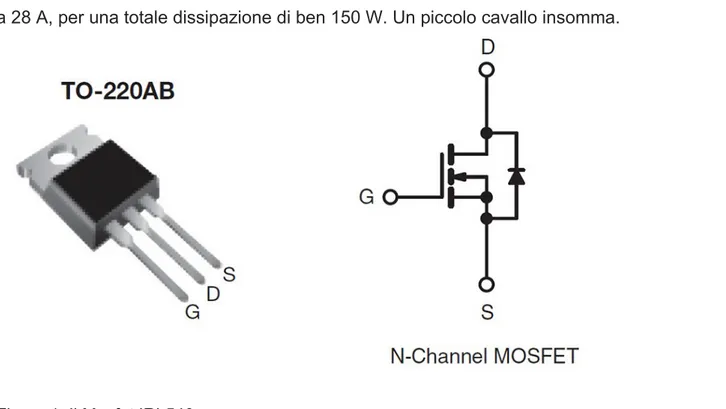
Logic-Level Gate Drive. È molto veloce, costa poco e ha una limitata Rdson che si traduce in una dissipazione quasi nulla e temperature basse di funzionamento. Inoltre il suo pilotaggio avviene senza problemi anche con una tensione di "gate" pari a 3.3 V. In figura 1 si può osservare il transistor (in contenitore TO220AB), assieme alla sua piedinatura. Le sue caratteristiche elettriche sono estremamente interessanti: la VDS massima è di 100 V, e la corrente massima di drain è pari a 28 A, per una totale dissipazione di ben 150 W. Un piccolo cavallo insomma.
Figura 1: Il Mosfet IRL540
Lampeggiatore ad alta potenza
Lo schema della figura 2 mostra Arduino collegato a una lampada di grossa potenza,
caratterizzata da una tensione di alimentazione di 12 V, una resistenza di 1 ohm, una corrente di assorbimento di ben 12 A e, quindi, una dissipazione di circa 144 W. Per illuminarla occorre una batteria molto grossa.
F igura 2: Schema elettrico con una lampada e un MOSFET
La lampada è collegata ad Arduino sulla porta 7. In caso di livello logico alto, il gate del Mosfet si trova ovviamente alla tensione di 5 V (ma non c’è praticamente passaggio di corrente, data la sua altissima impedenza d’ingresso) e il drain è attraversato dalla massima corrente (circa 12 A). In tale condizione l’IRL540 dissipa una potenza di circa 7 W, non male per pilotare un carico di quella portata. Se il transistor dovesse scaldare si dovrebbe prevedere un’adeguata aletta di
raffreddamento.
Lo sketch del lampeggiatore
La figura 3 riporta il semplicissimo listato del lampeggiatore. Il pin 7 è configurato come uscita digitale, all’interno della funzione setup(). La funzione loop(), invece, attiva e disattiva,
Figura 3: Lo sketch del lampeggiatore ad alta potenza
In figura 4 è riportato il grafico della corrente che attraversa la lampada, nel dominio del tempo, durante il funzionamento del prototipo.
Figura 4: Il grafico della corrente che transita sulla lampada
Motore in continua
Con tale componente è possibile anche pilotare un motore in corrente continua. Tramite la tecnica del PWM si può variare la sua velocità senza influire, peraltro, sulla coppia. La figura 5 mostra lo schema elettrico. Un diodo di ricircolo è montato in "antiparallelo" al carico, per eliminare i
Figura 5: Schema elettrico per il pilotaggio del motore in C/C
Lo sketch
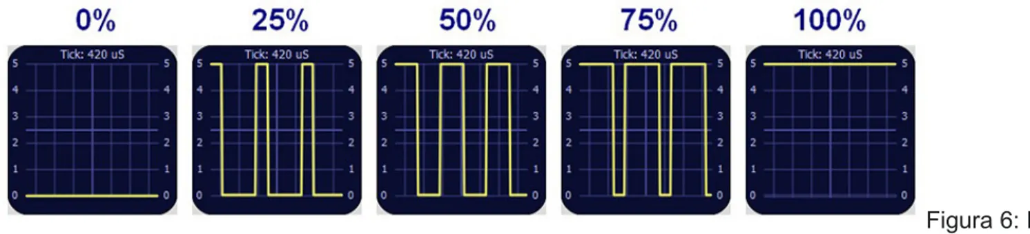
Il listato proposto in figura 6 ha lo scopo di pilotare il motore, secondo le seguenti diverse temporizzazioni e potenze: 5 secondi allo 0%; 10 secondi al 25%; 10 secondi al 50%; 10 secondi al 75%; 10 secondi al 100%.
Il motore aumenterà la propria velocità di rotazione a ogni variazione del duty cycle del segnale PWM, come evidenziato dagli oscillogrammi di cui in figura 6.
Figura 6: I vari duty cycles per le diverse velocità del motore
In figura 7 è riportato il semplice listato. Si ricorda che per adottare la tecnica del PWM occorre utilizzare solamente i pin di Arduino predisposti a tale tipologia di lavoro.
Beginning Arduino Programming (Technology in Action)
(2011)
Chapter 11. Continuing On
Hopefully, at this point you might have started to think that programming can actually be a lot of fun and you might be looking for new challenges. Naturally, everything that can be done with the Arduino can't be shown in one book, however, in this chapter we will continue on with new project ideas, new hardware, and new programming languages. We will even look at a few ways that you might get involved with the Arduino and open-source communities to share what you've learned and the projects you've made.
Rather than detail complete projects in this chapter, we will look at a few directions to take your learning and experimentation. These topics are loosely related to programming the Arduino— whether it's through compatible hardware or similar ideologies. I will provide you with a general introduction to each of these topics, as well as some resources for learning more, and give you a sense of how these things can interface with the Arduino. This is the bonus round really, just enough to keep you continuing on.
Build More Projects
The first thing to do, of course, with your newfound Arduino skills is build more projects! We couldn't cover every project idea in this one book and I tried to keep what we did talk about to the very basics. So, here are a few things that I would have loved to have previously discussed in more depth that you might be able to try out.
Bonus Project 1: Make Something Tweet
Remember that Arduino Ethernet Shield I suggested was a good idea when we learned how to log data on an SD card? Well, if you have this shield, or maybe one of the new boards called the Arduino Ethernet, then you can make your next project tweet. Maybe you're inspired by the functionality of the Botanicalls shown in Chapter 1, but rather than knowing that your plants need water, you want to know instead when the coffee in the office is ready or the beer keg has been emptied, maybe you really need to keep track of the irregular hours that your cat (or teenager?) enters and leaves the house, or maybe you just want to display an updated status of your whereabouts on a display in your office no matter where you are.
What’s Needed
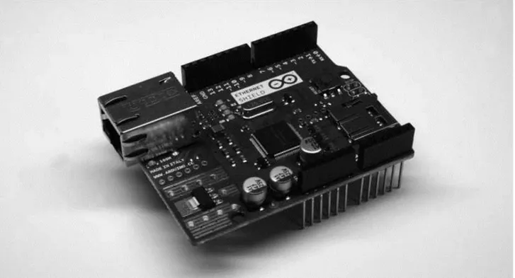
To get started tweeting with the Arduino, we need to use a few libraries and the appropriate hardware on the Arduino, along with a Twitter account and a little utility that was written especially for this that can be found at www.arduino.cc/playground/Code/TwitterLibrary. To begin, we will need the Arduino Ethernet Shield, as shown in Figure 11-1.
Figure 11-1. Arduino Ethernet Shield
With that in hand, we need to plug it into the Arduino and connect it to our network using an Ethernet cable. Next up, we need to install two of the four Arduino libraries, available from the earlier link, used in this application: Twitter and EthernetDNS. The other two libraries, SPI and Ethernet, come with Arduino versions 0019 and newer. Next up, we can start with the example sketch, SimplePost, included with the Twitter library and shown in Figure 11-2.
When the libraries are placed correctly in the libraries folder, the example sketch will show up in the File > Examples > Twitter menu, as shown. If not, you might need to hunt down the correct library folder.
■ Note You might have noticed that we’re using the 0022 version of Arduino in Figure 11-2. At the time of this writing, the Twitter library did not play nice with the 1.0 beta but the Arduino developers are working hard and I’m sure this will be fixed by the time this book is published.
Making It Work
With our sketch open, we need to set three things to make this work. The first thing to set is the MAC address of the Ethernet adapter. This is usually printed on a little label on the bottom of the Ethernet shield and entered in the array mac[]. Second, we need to find an available IP address on our network and enter it into the array named ip[]. Finally, we need to obtain an authorization token from Twitter to be able to use its services and enter this token in the Twitter twitter() object. To obtain this token, our example sketch uses the Arduino-tweet application at http://arduino-tweet.appspot.com. With all of that in place, we can upload the sketch to the interface board and then open up the Serial Monitor to see what's going on. When everything works, we should see the tweet posted by our Arduino, as shown in Figure 11-3.
Figure 11-3. Something tweeted
Okay, so “Hello, World!I'm Arduino!”is perhaps not the most exciting thing to tweet, but it's a start right? With the right kind of sensors, I'm sure you can find something interesting to make tweet using these libraries. Or maybe instead, you can get the Arduino to display incoming tweets on an LCD or other form of display. For more ideas on what to do with the Arduino Ethernet Shield, check out the following tutorials from bildr, the modular tutorial site:
http://bildr.org/20ll/06/arduino-ethernet-pin-control/ http://bildr.org/20ll/06/arduino-ethernet-client/ Bonus Project 2: Make Something Move
We also didn't get a chance to talk much about making things move. We did have a look at connecting a small DC fan back in Chapter 6, and in Chapter 9 we discussed servo and stepper motors as way to make something move with fairly precise positioning. You might instead want to make something move using common and very popular DC motors. As explained in more depth in
the next chapter, DC motors come with and without gearboxes and run at a variety of speeds with different current requirements. The following are three possible things that we can look for when connecting DC motors to the Arduino:
• The motor can run at variable speeds • The motor can run at high currents • The motor can switch directions
Of these three things—in a simple circuit that we are not throwing the kitchen sink at—we can usually do two of these at any one time. So for example, we can run a motor at high currents and at a range of speeds, but it's a little more difficult to get it to switch directions. Instead, we could have a motor change direction, but we would then need to decide whether a high current or variable speeds is more important.
The code to work with DC motors is fairly simple using a combination of digital and/or analog outputs, which we covered somewhat thoroughly in Chapters 5 and 6. The circuits, however, are a little more complex, and we won't be able to go into all the complexities here, but let's cover three simple ways to interface DC motors that illustrate the rule of variable speeds/high currents/switching directions with a general explanation on how to make each circuit work. We'll leave the specifics up to you for further exploration.
MOSFETs
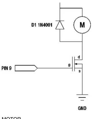
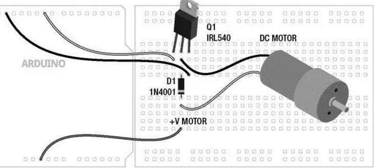
The Metal Oxide Field Effect Transistor, or MOSFET, is one of the simpler components to use with DC motors along with the basic transistor shown in Figure 6-4 of Chapter 6. The following circuit in Figures 11-4 and 11-5 uses an IRL540 MOSFET, although others would work as well, to switch a motor with a load of up to about 20 amps. That's a pretty big motor! The IRL540 can also switch at a very fast rate of speed, so we can use PWM to control the speed of a motor connected in this circuit. This circuit also uses a 1N4001 diode connected to the positive and negative side of the motor to prevent any electrical surges from the motor damaging the MOSFET.
■ Note In all of these motor circuits, we have a pin that is marked +V MOTOR. While we have connected these to our standard +5 VDC supply because our motors worked on +5 volts, you may need to connect these pins to a larger power supply, depending on the needs of your motor.
+V MOTOR
MOTOR Q1 IRL540
Figure 11-4. MOSFET and DC Motor schematic
d s ց
+5VDC
Figure 11-5. MOSFET and DC Motor illustration
When connected to pin 9 on the Arduino board, we can either control the motor digitally, meaning turn it on or off, using the digitalWrite() function or we could instead control the speed of the motor using PWM and the analogWrite() function with 0 being off and 255 being full speed forward. This high current and variable speed comes with the drawback that we can only control the motor in one direction.
H-Bridges
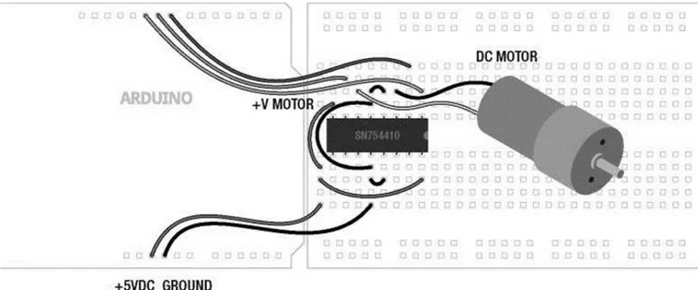
We have already used the SN754410 H-bridge integrated circuit in Chapter 9 to control a bipolar stepper motor, but we can also use it to control up to two DC motors, although we have only shown it with one in Figures 11-6 and 11-7. By using a couple of the Arduino's digital outputs, we can control the direction of the motor as well as its speed using one of the PWM pins. This, however, comes at the cost of the size of the motor, with the SN754410 only capable of 1-amp output capacity. GND GND PIN 10 PIN 8 MOTOR M PIN 9 +V MOTOR
1,2 EN +5 VDC 1 IN 4 IN 1 OUT 4 OUT GND GND GND GND 2 OUT 3 OUT 2 IN 3 IN +V MOTOR 3,4 EN SN754410 +5 VDC
Figure 11-6. H-Bridge and DC Motor schematic PINS 8, 9, 10
Figure 11-7. H-Bridge and DC Motor illustration
When configured as shown, pins 8 and 9 will control the direction of the motor using digital outputs and the digitalWrite() function, while pin 10 will control the motor's speed using analogWrite() with 0 being off and 255 being full speed ahead. To get a sense of how these two pins control the direction of the motor, see Table 11-1.
Table 11-1. H-Bridge Function
Input 1 Input 2 Function
HIGH LOW Spin motor clockwise
LOW HIGH Spin motor counter-clockwise LOW LOW Disable motor / free spin HIGH HIGH Motor brake / full stop
By writing a HIGH signal on pin 8 and a LOW signal on pin 9, then the motor will spin one direction and will reverse direction when pin 8 is LOW and pin 9 is HIGH. If both pins are LOW, then the motor will have 0 voltage and will spin freely—assuming it's not a gear motor. If both pins
are set to HIGH, then current will be applied to both sides of the motor, locking the motors position just like an electronic brake.
From here, all you need to do is set the direction using pins 8 and 9, then control the speed with analogWrite() on Pin 10, and you're up and running with an H-bridge.
Relays
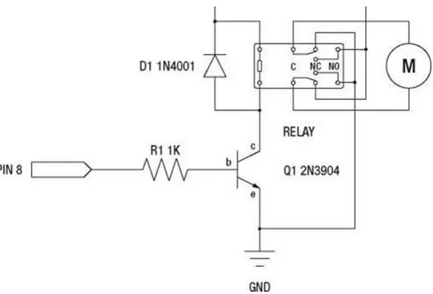
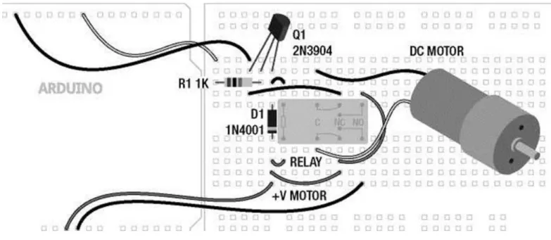
In this project, we will briefly look at using a mechanically switching relay to handle high currents and switch directions with a DC motor. Relays work a little like the light switches in our walls, with little metal contacts inside the switch, which are physically moved whenever the switch is activated, completing a circuit. This is done by sending a digital signal to a little magnetic coil inside the relay that activates the switch for us. In Figures 11-8 and 11-9 we are using the Axicom D2N V23105 relay with a +5v coil that can control a motor of up to 3 amps at a ridiculously high voltage of +220 volts.
+5 VDC +V MOTOR
MOTOR
Figure 11-8. Relay and DC Motor schematic
GROUND PIN 8
□ □ □ □ □ □
+5VDC GROUND
Figure 11-9. Relay and DC Motor illustration
This circuit is a little more complex, but it gives us bi-directional control of the motor using a single digital output, and we have a high amount of current to play with. Alas, this is at the cost of the ability to control the speed of the motor because the relay simply cannot switch at a very fast speed. Inside of the relay there are actually two switches with two positions each: normally open and normally closed. With the wiring as shown, when the relay is activated, the motor will be connected to the power supply in one direction and when the relay is off the motor will be connected in the opposite direction. This also means that the motor will always spin in one direction or another. This circuit doesn't quit!
While the coil of the relay is rated for +5v, I don't trust it with the microcontroller, so we've used a 2N3904 transistor to switch the relay on or off and a 1N4001 diode to protect the transistor from surges, like we did with the MOSFET. And finally, no two relays are ever really the same, so double-check the wiring for your relay before wiring this up.
That might have been a lot to take in, but the code is really simple and this brief little introduction to motors and the Arduino should be enough to send you on your way to find more information and give it a try.
Bonus Project 3: Mega-Size Something
Our final project idea isn't so much a project as it is a neat piece of hardware. Throughout this book, our projects have been written for the standard Arduino interface board, the Arduino Uno. The Uno, however, has a bigger brother called the Arduino Mega 2560, shown in Figure 11-10, and its capabilities should inspire new projects.
Figure 11-10. Arduino Mega 2560
The Mega 2560 is bigger than the little Uno in every way—it has 54 input and output pins, more than four times that of the Uno, 14 of which can be used for PWM; ten more analog inputs, for 16 total; four hardware serial ports instead of one; eight times the program memory at 256 kilobytes and four times the RAM and EEPROM space. Not only can it hold bigger sketches, it can, for example, control the speed of 14 DC motors, read from 16 different analog sensors, or even easily switch 128 LEDs with no additional hardware or tricky wiring needed. While there are always extra hardware components that can give the Uno similar levels of capabilities, the Mega 2560 doesn't need them, simplifying your wiring and your code.
Speaking of code, the Arduino Mega 2560 works pretty much just like its little brother. The pins used for I2C are in a different location and there are extra hardware serial ports, but otherwise the same code should work just fine on the Mega. The Mega is also compatible with most of the shields made for the Uno, including the Ethernet Shield, so the next time you need to blink a ton of LEDs, you might want to consider using the Arduino Mega 2560.
15A 400W MOSFET AOD4184A to control motor or load
Connecting load and using MOSFET as Switch or PWM driver
Data Sheet for AOD4184A MOSFET
Code example using resistor
/** This is Arduino Sketch for Tutorial video
* explaining why resistor is needed to be used with push button * with Arduino to connect the pin to Ground (GND)
*
* Written by Ahmad Shamshiri on July 18, 2018 at 17:36 in Ajax, Ontario, Canada * For Robojax.com
* Watch instruction video for this code: https://youtu.be/tCJ2Q-CT6Q8
* This code is "AS IS" without warranty or liability. Free to be used as long as you keep this note intact.
*/
int motorPin =9;// pin to connect to motor module int mSpeed = 0;// variable to hold speed value
int mStep = 15;// increment/decrement step for PWM motor speed
void setup() {
// Robojax.com demo
pinMode(motorPin,OUTPUT);// set mtorPin as output Serial.begin(9600);// initialize serial motor Serial.println("Robojax Demo");
}
void loop() {
// Robojax.com tutorial
analogWrite(motorPin, mSpeed);// send mSpeed value to motor Serial.print("Speed: ");
Serial.println(mSpeed);// print mSpeed value on Serial monitor (click on Tools->Serial Monitor)
mSpeed = mSpeed + mStep; // See video you for details.
if (mSpeed <= 0 || mSpeed >= 255) { mStep = -mStep; } delay(200); }
Testing MOSFET AOD4184A using 5A, 10A, 15A, 20A and 25A
load
/*
* This is Arduino Sketch for Tutorial video
* explaining the 15A MOSFET AOD4184A used as switch
* this sketch used to test the moseft with load at 5A, 10A, 15A, 25A *
* Written by Ahmad Shamshiri on July 21, 2018 in Ajax, Ontario, Canada * For Robojax.com
* Watch instruciton video for this code:https://youtu.be/tCJ2Q-CT6Q8
* This code is "AS IS" without warranty or liability. Free to be used as long as you keep this note intact.
*/
int loadPin =9;// load pin
void setup() {
// Robojax.com demo pinMode(loadPin,OUTPUT); Serial.begin(9600);
Serial.println("Robojax Demo"); }
void loop() {
// Robojax.com tutorial digitalWrite(loadPin, HIGH); while(1);// wait forever