UNIVERSITY OF SIENA, ITALY
COMPUTER ARCHITECTUREGROUP
PHDPROGRAM OF INFORMATIONENGINEERING AND SCIENCE (IES) CYCLE: XXIX
A
N
E
FFICIENT
N
O
C-
BASED
F
RAMEWORK
T
O
I
MPROVE
D
ATAFLOW
T
HREAD
M
ANAGEMENT
A
T
R
UNTIME
A thesis submitted in fulfilment of the requirements for the degree of Doctor of Philosophy
Doctoral Candidate:
Somnath M
AZUMDAR
Director of the PhD Program in IES:
Prof. Antonio V
ICINO
“Not everything that can be counted counts. Not everything that counts can be counted.”– William Bruce Cameron [Informal Sociology: A Casual Introduction to Sociological Thinking]
It was indeed an amazing journey. Similar to other PhD students, there are many times where the academic grind and struggle of completing this doctoral degree seems overwhelming. However, I must thank Prof. Antonio Vicino, Prof. Stefano Maci, Prof. Marco Maggini and Prof. Chiara Mocenni for putting me in the right place to keep me going and giving me the peace of mind to complete this doctoral work. I also have to say thank you to Alberto Scionti, Prof. Marco Pranzo and Prof. Anoop S. Kumar allowing me to explore interesting research works, and most importantly supporting me through this doctoral work. It was invaluable to have such supporters who supported my ideas and worked with me to solve them.
From the personal note, I have to thank my mother and my father for their consistent emotional support. These people are the ones more excited than me about this PhD!! I also offer sincere thanks to Mr. Prem G. Krishnan, Choti, and Bachcha for their uncountable supports in the crucial time of my PhD.
execution model can be managed at Network-on-Chip (NoC) level. The roots of the dataflow execution model date back to the early 1970’s. Applications adhering to such program execution model follow a simple producer-consumer communication scheme for synchronising parallel thread related activities. In dataflow execution environment, a thread can run if and only if all its required inputs are available. Applications run-ning on a large and complex computing environment can significantly benefit from the adoption of dataflow model.
In the first part of the thesis, the work is focused on the thread distribution mecha-nism. It has been shown that how a scalable hash-based thread distribution mechanism can be implemented at the router level with low overheads. To enhance the support fur-ther, a tool to monitor the dataflow threads’ status and a simple, functional model is also incorporated into the design. Next, a software defined NoC has been proposed to manage the distribution of dataflow threads by exploiting its reconfigurability.
The second part of this work is focused more on NoC microarchitecture level. Tra-ditional 2D-mesh topology is combined with a standard ring, to understand how such hybrid network topology can outperform the traditional topology (such as 2D-mesh). Fi-nally, a mixed-integer linear programming based analytical model has been proposed to verify if the application threads mapped on to the free cores is optimal or not. The proposed mathematical model can be used as a yardstick to verify the solution quality of the newly developed mapping policy. It is not trivial to provide a complete low-level framework for dataflow thread execution for better resource and power management. However, this work could be considered as a primary framework to which improvements could be carried out. [303 words]
List of Figures ix
List of Tables xiii
1 Introduction 1
1.1 Thread management issues . . . 3
1.2 Research problem and associated solutions . . . 4
1.3 Thesis structure . . . 7 2 Background 9 2.1 Dataflow threads . . . 9 2.2 Hardware overview . . . 14 2.3 Interconnection subsystem . . . 20 2.4 Summary . . . 28 3 Thread Distribution 29 3.1 Introduction . . . 29
3.2 DF-Threads and its scalability . . . 31
3.3 Program Execution Model (PXM) . . . 33
3.4 Proposed Architecture . . . 35
3.5 Hash Scheduling Function . . . 38
3.6 Evaluation . . . 39 3.7 Summary . . . 41 3.8 Acknowledgement . . . 41 4 Monitoring 43 4.1 Introduction . . . 44 4.2 System model . . . 44 4.3 RADA’s implementation . . . 46
4.4 Dealing with heterogeneity . . . 48
4.5 Evaluation . . . 52
4.6 Summary . . . 55
4.7 Acknowledgement . . . 56
5 Thread Management at Software defined NoC 57 5.1 Introduction . . . 58
5.2 System overview . . . 59
5.3 NoC software interface . . . 61
5.4 Proposed Network-on-Chip architecture . . . 62
5.5 Evaluation . . . 65
5.6 Summary . . . 68
5.7 Acknowledgement . . . 68
6 Customised NoC Architecture 69 6.1 Introduction . . . 70
6.2 System overview . . . 72
6.3 Proposed Network-on-Chip architecture . . . 73
6.4 Evaluation methodology . . . 80
6.5 Applicability and future improvements . . . 90
6.6 Summary . . . 93
6.7 Acknowledgement . . . 94
7 Analytical Model 95 7.1 Introduction . . . 95
7.2 Problem description and assumptions . . . 97
7.3 Mathematical formulation . . . 101
7.4 Simulation results . . . 103
7.5 Summary . . . 114
7.6 Acknowledgement . . . 115
8 Conclusion and Future Work 117 8.1 Contribution . . . 117
8.2 Future work . . . 119
1.1 Solution overview: Target chip overview for the manycores clustered pro-cessor. Cores are organised into clusters (i.e., nodes) connected each other through a 2D mesh. Within each node, cores and other shared resources are linked via a ring. Each node has a dedicated node manager that con-trols the runtime and also monitor the system. Each core has a local scheduling unit to distribute the threads. Blocks that are addressed in
the thesis are highlighted via dotted line. . . 8
2.1 Block diagram of parallelism: application level parallelism (left), thread level parallelism (middle) and instruction level parallelism (right) . . . 10
2.2 Thread execution using control and data signals . . . 10
2.3 Programming models classification . . . 11
2.4 Some well-known topology for interconnect subsystem . . . 21
2.5 XY DoR routing direction (left) and block diagram of a mesh router archi-tecture is presented (right) . . . 23
3.1 Instruction count normalised to the matrix size 256. . . 32
3.2 Speedup of user cycles count normalised to the matrix size 256. . . 32
3.3 Scaling of read and write operations for DF-Threads. . . 33
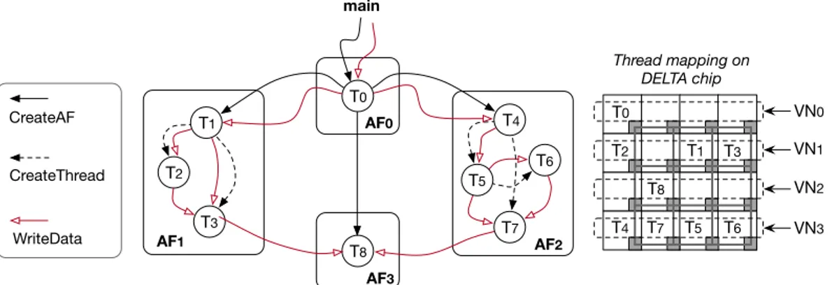
3.4 A simple kernel application adhering with the proposed PXM and a possi-ble mapping of threads on the PEs. . . 35
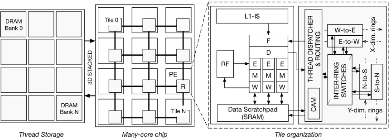
3.5 Chip organization: tiles contain a PE (white box) and router (gray box). The scratchpad substitutes the traditional L1-data cache. . . 36
3.6 Thread Dispatcher module organization (left) with the internal structure of the H(·)function (right). . . 37
3.7 NoC performance: distribution of threads on the PEs (a), average through-put (b), and power consumption (c). . . 40
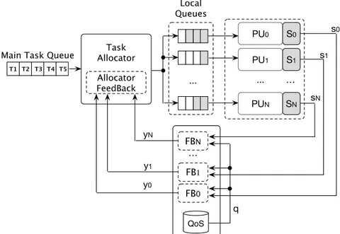
4.1 System overview: the abstract machine model used to managing execution of dataflow threads. . . 45
4.2 Implementation of the proposed system. . . 47
4.3 Negative feedback closed-loop based task scheduling system of the RADA. 48 4.4 A code snippet of the recursive Fibonacci kernel: the code highlight the software interface exposed by RADA, which simplifies the amount of code needed to synchronise threads’ activities. . . 51
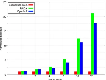
4.5 Recursive Fibonacci sequence: evaluation of the RADA and OpenMP exe-cution. . . 52
4.6 Block matrix: evaluation of the RADA and OpenMP execution. . . 53
4.7 Number of requests issued to the SU by the recursive Fibonacci kernel (single node, 8 cores). . . 53
4.8 Score function obtained from the execution of the BMM kernel running on host CPU and Intel Xeon Phi accelerator. . . 55
5.1 Mapping between the physical network with a 2D-mesh topology, and a multi-level virtual topology. Links to the physical network are organised into local rings (blue lines) and a global 2D-mesh among rings (purple lines). 59 5.2 The lightweight router microarchitecture. Ring stations (RSs) have injec-tion and ejecinjec-tion ports, and bypass (blue squares) and power-gating (red squares) bits. Inter-ring switches are power-gated depending on the state of the RS (grey circles are OR/AND gates). . . 63
5.3 The internal structure of a RS with BP/PG bits and the link counter in the network interface (dashed lines represent selection signals for multiplex-ers/demultiplexers). . . 64
5.4 An example of virtual topology mapping: Grey structures represent com-ponents (i.e., interconnections, RSs or inter-ring switches) of the router that are power-gated. Red lines correspond to active links used to build local rings, while green lines show links of the mesh. Furthermore, green boxes represented components set in bypass mode and used to construct the mesh among the virtual rings correctly. . . 65
5.5 Distribution of random traffic over 1024-based CMP. . . 66
6.1 An instantiation of the proposed scalable NoC: 256 PEs organised into 4×4 block units, each connecting four ringlets. . . 74
6.2 Modified 2D-mesh router microarchitecture: two groups of local/global channels are used to manage traffic within the 2D-mesh and traffic ex-change with local ringlets. . . 75
6.3 Timing: a) best-case (success) and b) worst-case (failure) of pre-arbitration. 76 6.4 The microarchitecture of the RS of the ringlet’s master: horizontal dimen-sion is used to create the bidirectional ring connection, while vertical di-mension connects the mesh router and local PE of the ringlet. . . 77
6.5 Packet header organisation. . . 79
6.6 Static and dynamic power distribution . . . 82
6.7 Total power consumption with increasing network size. . . 83
6.8 Average packet latency in uniform random traffic pattern. . . 85
6.9 Average packet latency in bit-reversal traffic pattern. . . 85
6.11 Average network throughput in uniform-random traffic pattern. . . 87
6.12 Average network throughput in bit-reversal traffic pattern. . . 87
6.13 Average network throughput in transpose traffic pattern. . . 88
6.14 Average packet latency with increasing network size. . . 89
6.15 Average network throughput with increasing network size. . . 90
6.16 Comparing average network throughput and average packet latency with increasing network size. . . 91
6.17 Internal organisation of the morph control packet (left), and the corre-sponding control structures in the mesh router (right). . . 92
7.1 Representation of multiple application running on a NoC . . . 98
7.2 NoC model representation: via architectural model (left) and also via the-oretical model (right) . . . 98
7.3 Basic system graph representation including application threads and as-sociated single memory controller . . . 100
7.4 T2C mapping process in zig-zag heuristic algorithm for NoC size 4×4 . . 103
7.5 Relative average traffic performance . . . 110
7.6 MC influence on four algorithms while objective function is energy cost and latency . . . 111
7.7 Comparing latency with energy cost with different network sizes . . . 111
7.8 Performance comparison between 5×6 and 4×8 . . . 113
7.9 Comparing the queue length for network size 4×8: (left) MC=1, (right) MC=2 . . . 113
7.10 Comparing the queue length for network size 5×6: (left) MC=1, (right) MC=2 . . . 114
2.1 Theoretical performance of 8x8 mesh for six synthetic traffic patterns . . 25
4.1 The execution trace (first 10 entries) for the RFS kernel with the input size set equals to n=10. . . 54
4.2 The execution trace (first six entries) captured from one PE when running RFS kernel with size n=10. . . 54
6.1 Mesh-router: main microarchitectural parameters. . . 76
6.2 Area and power comparison between a standard router architecture and the proposed mesh router. . . 81
6.3 Relative resource utilisation in Vivado (values are in percentage). . . 81
7.1 Experiment configuration . . . 104
7.2 Problem size for the MILP0model . . . 105
7.3 Performance of MILP0model while the objective function is minimisation of energy cost . . . 106
7.4 Performance of MILP0model while the objective function is minimisation of latency . . . 107
7.5 Performance of MILP model while the objective function is minimisation of energy . . . 107
7.6 Performance of MILP model while the objective function is minimisation of latency . . . 108
7.8 Gap from the LB(MILP) which is the best attainable for the three algo-rithms (MILP, ZZ, RND) while minimising the latency . . . 109
7.7 Gap from the LB(MILP) which is the best attainable for the three algo-rithms (MILP, ZZ, RND) while minimising the energy cost . . . 109
1
Introduction
In recent years, applications have evolved from simple, monolithic, centralised execu-tion model to highly agile, distributed and dynamic model. These transformaexecu-tions have forced to make changes in the hardware microarchitecture for better support at the software level. The functional part of computation unit has also evolved a lot due to the changing nature of user applications. Some well-supported features of the current ap-plications are: i) dynamic scaling (up and/or down) of number of processing cores as the execution time progresses (e.g., MapReduce programming framework); ii) requirement of heterogeneous processing cores (supported by e.g., asymmetric CMPs (chip multi-processors), Cell broadband engine processor, ARM’s bigLITTLE technology). Today’s applications also started to become communication-centric. A huge part of the proces-sor chip’s power budget is used to transport the data packets from/to cores and also to the memory modules. Current and future multi-/many-cores will be hosting multiple applications to improve the performance per unit energy. The primary aim of sharing the CMPs by multiple applications is to improve the overall resource utilisation of the system. However, improving the resource utilisation without creating the resource con-tention and also the workload imbalance is a very critical task. The solution should be holistic and must follow Hardware/Software Codesign approach. Here, the software could be used for flexibility, and hardware for higher performance.
The nature of the execution flow in the applications can differ significantly. Thus, the proposed software solutions cannot be generic. The higher proportion of today’s software application follows traditional control-flow approach. As a consequence, the state-of-the-art hardware is also tailored to that. There is another execution model that execute threads based on the availability of input data called Dataflow execution model. The advantage of this model is that independent portion of the application can be ex-ecuted in parallel when their input data are available. In this doctoral work, dataflow based execution model is used. Parallelism can be achieved at different levels.
tion threads allow parallelizing code inside the applications to reduce overall execution time. Most common form of parallelism are i) instruction-level-parallelism, ii) data level parallelism (DLP) and iii) thread-level-parallelism (TLP).
Dataflow architecture was initially introduced for ILP [Den80]. It was also initially implemented in the form of “restricted dataflow” in a superscalar processor [HP86]. Later, a similar concept had been investigated by [AN90] also to support threads. Soon this effort led to an explicit token-store (ETS) architecture based machine known as Monsoon [PC90]. The dataflow execution model also supports DLP, but this work is focused on the TLP support of dataflow. During TLP, the total execution time would be equal to the execution time of the longest-executing thread if all threads in an ap-plication started to execute independently. In apap-plications, TLP can also be exploited using other execution models (such as fork-join, master/slave, divide and conquer). Cur-rent CMPs can run a variety of complex applications consisting of a massive number of concurrent threads. Today, a single core can support concurrent execution of multiple threads (known as simultaneous multithreading (SMT)). Well-known hardware such as Intel’s core architecture supports two threads each core and Xeon Phi co-processor that can support four threads per core.
Today’s applications are long running, multithreaded and have different resource re-quirements. Only the microarchitectural advancements are not enough to execute appli-cations in the best possible way along with proper programming model. Both hardware and software support for threads is also necessary. Hardware-based support for explicit multithreading can facilitate smooth execution of fine-grain threads and offer advan-tages over managing them at the software level. Conversely, software based thread supports can lead to higher performance loss (as the number of thread increases). The situation may get worst for large, complex and long running parallel applications. In general, dedicated hardware module offers low overhead and faster execution time, but requires altering existing hardware. On the other hand, software components are eas-ier to add and manage, while new hardware support could increase performance. Before proposing a dedicated or new hardware module into the existing system, we should con-sider the associated design time, also the increased area and power cost.
The functionalities and also the complexities of manycore chips are increasing due to the immense evolution of chip’s microarchitecture. Different applications have different resource requirements. A typical hardware execution unit consists of various depen-dent components (such as cores, local memory, DRAM controller, I/O controllers) and software plays a crucial part to tie them together for executing applications. With in-creasing core counts, contention reduction among shared resources is a challenge. The interconnection subsystem is becoming a vital component for better performance for manycore chips. Stable performance becomes dependent on the contention of other
cru-cial functional components (such as memory hierarchy and interconnections) as the core count of the chips are increasing. Today’s, popular interconnection subsystem for CMPs is known as Network-on-chip (NoC) which is mainly an embedded switching network to interconnect the processing cores inside a CMP.
Multiple topologies are available or proposed from the scientific community. Two-dimensional mesh (2D-Mesh) is the most popular topology. In recent years, the NoC research domain has matured enough. Managing threads at low-level have several ad-vantages (such as fewer hotspots, better performance, efficient power utilisation are few among others) unfortunately managing the threads at NoC level has not gained more attention. NoC is not just a topological layout of processing cores inside a silicon die, but also an effective network to route the data packets between the cores and also between the primary memory. Here, we advocate for the adaptation of NoC level thread manage-ment. This approach can facilitate the adaptation of low-level thread management for better control of data packets and also the floor planning for energy efficient execution. This method could also adapt itself to operational conditions (such as hotspots). In this work, a dataflow-based program execution model (PXM) has been used to map and dis-tribute threads. Next, a software defined NoC, and also a hybrid NoC topology has been proposed keeping in mind to be used with the proposed thread distribution mechanism.
1.1 Thread management issues
The application threads are executed in a dynamic environment. For the smooth and efficient execution of applications, the system architecture needs to dynamically adapt the “ever changing” situations with minimal commotion to the functionality they offer. The change can come from various sources (such as resource contention, failure of hard-ware components, or may be a specific requirement of running applications). The known issues can be broadly grouped into two groups. They are:
• Non-uniformity and in-elasticity Each application (no matter whether they are a regular type of application or irregular type of application) may be composed of several hundreds of concurrent threads. A single solution may not be appro-priate for all types of application threads, so customisation is needed for better performance. The main issue of today’s applications is that their natures are not predictable easily. Managing threads at runtime using available resources are not easy. The traditional approaches to tackling the runtime thread management limit the overall flexibility of the underlying hardware.
• Runtime prediction Runtime prediction for resource requirements by threads is very complex to envisage. It is very complex to forecast the influence of the
appli-cation on the current system. There also exists I/O stalls or hardware component failures to make the situation more complicated.
Resource sharing opportunity arises when multiple computing elements connect in-side a system. A proper resource management must be in place to harness the inherent facilities in a distributed computing platform where opportunities [MHH+15, CGMP10] of sharing processor core’s content, hardware resources [GAD+13], and other services
exists. However, developing an effective resource management ecosystem for “oppor-tunistic” computing environment is not easy. An application is a collection of multiple sub-tasks which can communicate each other and also may be dependent on each other. These scenarios are ideal for I/O stalls or memory stalls. Furthermore, this situation can lead to reduced performance. Thus, we need to make a (low-level) ecosystem which is simple, scalable and yet efficient enough for executing applications at higher perfor-mance and with lower energy cost. In general, multiple efficient software, as well as the hardware based solution, have been proposed for addressing the issues belonging to the groups as mentioned above. Some of the recently proposed solutions also consider the current hardware microarchitectural changes (such as increased complexity at last level cache (LLC), prevailing heterogeneity at core level).
1.2 Research problem and associated solutions
Recent times power aware computing has gained importance. As a consequence, the microarchitectures are becoming more energy efficient. Power-aware approach some-how leads to multicores concept and later to the manycores. Apart from the increased core count, this approach also helps to steer the microarchitecture from homogeneous to heterogeneous. The increased core count offer the higher degree of parallelism. In-terconnection and memory modules are the critical subsystems which are shared by all cores for data exchange. NoC is a scalable communication architecture that offers advantages compared to other alternatives (such as bus, ring) because both topologies suffer from high energy consumption, low scalability, and low bandwidth for connecting a large number of processing cores. Apart from that, NoC also offers better scalability, productivity and more deterministic performance [DT01].
For better energy efficiency and scalability, this research work advocate for an ap-propriate means of distributing and monitoring dataflow based application threads at NoC level. However, the proposed approach is also flexible enough to be used for control-driven applications. Results also show the efficiency of the simple hash based policy pro-posed for concurrent, large thread distribution model. A hybrid NoC architecture has been developed on the state-of-the-art FPGA device for underlying support. The
pro-posed hybrid NoC is application-aware by providing the support to scale (up or down) its size as per applications requirement. The primary research question that has been addressed in this work is:
How a NoC-based framework composed of multiple components (mainly for thread execution, distribution and monitoring) can improve the runtime adaptability of dataflow program execution models?
In other words, the goal of this research is to enhance the runtime adaptability of dataflow thread management policy by providing a scalable and efficient hybrid NoC topology. The framework can manage and also monitor the threads while lowering the energy consumption. The proposed hybrid NoC design is also flexible enough to adapt to the changing resource requirements of applications at runtime. The doctoral work solves the research problem via five steps. They are:
Step: 1 (Aim: Thread Distribution and Execution): How to easily distribute the
massive number of concurrent threads at low levels so that it become energy efficient? Article I (Chapter 3) gives the detailed the hash-based thread distribution scheme that can be very efficient with simple hardware modification. The proposed scheme tar-gets dataflow execution model and offers abstraction and flexibility.
Based on the Paper: “Enabling Massive Multi-Threading with Fast Hashing” by Al-berto Scionti, Somnath Mazumdar and Stéphane Zuckerman.
Status: Accepted for publication at IEEE Computer Architecture Letters (CAL).
Step: 2 (Aim: Thread Monitoring): How can we monitor the multithreaded
dataflow applications?
The main aim of Article II (Chapter 4) is to propose a simple tool to analyse dataflow-based applications at runtime. It aims at a faster evaluation of hierarchical dataflow execution model. The output provided by the tool can be of great help in analysing the traffic generated by the scheduling activity.
Based on the Paper: “Analysing Dataflow Multi-Threaded Applications at Runtime” by Somnath Mazumdar and Alberto Scionti.
Status: Published at the 7th IEEE Advance Computing Conference (IACC-2017).
Step: 3 (Aim: Thread Execution Support): How to manage threads at
Software-defined NoC level?
Article III (Chapter 5) discusses this challenge by proposing a scalable Software de-fined NoC (SDNoC) architecture for future manycores. The proposed interconnect allows mapping different types of topologies (virtual topologies). In this work, the software layer can directly control the network topology to accommodate different application re-quirements and communication patterns.
Based on the Paper:“Software defined Network-on-Chip for scalable CMPs” by Alberto Scionti, Somnath Mazumdar and Antoni Portero.
Status: Published in IEEE International Conference on High Performance Computing & Simulation (HPCS), (pp. 112-115), 2016.
Step: 4 (Aim: NoC microarchitecture): Provide an efficient NoC
microarchitec-tural design to exploit the network traffic localisation for better traffic management at low energy cost.
Article IV (Chapter 6) gives a detailed account of a hybrid, scalable and efficient NoC microarchitecture that is designed to support future manycores chips. Similar to Article III, it also fuses ring and 2D-Mesh topology to provide high-performance while processing local (rings) and global (mesh) traffic efficiently. The results show that it is indeed efficient compared to the traditional 2D mesh topology.
Based on the Paper: “A High-Performance Interconnect for Future Scalable Manycore CMPs” by Somnath Mazumdar and Alberto Scionti.
Status: Under review at Journal of Parallel and Distributed Computing, Elsevier.
Step: 5 (Aim: Thread-to-Core Mapping): Provide an efficient analytical mapping
model to certify the mapping of threads onto the cores are optimal or not.
Article V (Chapter 7) proposes a mixed integer linear program based formulation to map threads on cores at worst-case scenario by keeping into account the spatial topology of 2D-mesh NoC. The proposed analytical model is general enough to consider a different optimising policy (either optimising energy or latency) together with a variable number of memory controllers.
Based on the Paper: “An Analytical Model for Thread-Core Mapping for Tiled CMPs” by Marco Pranzo and Somnath Mazumdar.
Status: Under review at IEEE Transactions on Computers.
1.2.1 Solution overview
The proposed framework incorporates a flexible dataflow thread management mech-anism that can efficiently distribute dataflow threads across the available processing cores. The proposed hybrid NoC topology can manage the traffic inside the NoC first by dividing them as local and global. Apart from that, the topology exploits the idea of “traf-fic localisation” to improve the overall energy cost to transport data packets. The con-tribution on the main research issues related to the problem is described in figure 1.1. The figure presents the target architecture with its basic functional block diagram, and the dotted line represents the contribution of this work. The proposed framework relies on three main components:
• Dataflow based approach: is used to enhance the degree of parallelism avail-able in a dataflow application. Dataflow mainly explores the “spatial parallelism” upon the input available. Spatial parallelism is based on the concept that a thread
can execute in parallel if there exist enough space (resources or processing cores) and the associated input is available. We consider the dataflow model as it has fewer management issues and the available general purpose hardware can be used to exploit the inherent parallelism of the dataflow applications.
• Thread distribution and monitoring: is a critical feature while managing a huge amount of concurrent threads at runtime. In the framework, hashing based an effective thread distribution policy is used with a small amount of HW over-heads. This work also proposes an analytical model for evaluating the solution quality of mapping threads on the free cores (in a 2D-mesh NoC). It provides a (theoretical) optimum solution for variable NoC sizes. Finally, a simple, yet pow-erful tool has also been proposed to monitor the threads at runtime.
• Hybrid NoC topology: takes into account the infrastructural maintenance is-sues during the thread execution. To counter the runtime management isis-sues, a hybrid NoC architecture works in such a way so that with increasing data traffic, the system is stable with the continuous rise in throughput and also with better power consumption compared to the traditional 2D-mesh topology. The current state-of-the-art NoC subsystem is complex enough to maintain the threads at such low level with efficient topology layout and smart thread management but with a few overheads for implementing hardware-based thread distribution policy.
1.3 Thesis structure
The thesis is organised as:• Chapter 2 presents state-of-the-art of the related works. It presents the basic information about the used programming model, with its execution models along with its related hardware supports. The brief information about some current manycores and the NoC has also been given.
• Chapter 3 presents hash-based thread distribution scheme for manycores. It describes how this distribution scheme can solve massive concurrent thread man-agement issues at the hardware level with little overheads.
• Chapter 4 details a runtime analysis tool that can be used to evaluate the dataflow applications. It aims to be a simple simulation tool for fast evaluation of applications adhering to dataflow PXMs.
• Chapter 5 presents a scalable Software defined Network-on-Chip (SDNoC) architecture to provide the execution support for threads based on dataflow PXMs.
Figure 1.1: Solution overview: Target chip overview for the manycores clustered processor. Cores are organised into clusters (i.e., nodes) connected each other through a 2D mesh. Within each node, cores and other shared resources are linked via a ring. Each node has a dedicated node manager that controls the runtime and also monitor the system. Each core has a local scheduling unit to distribute the threads. Blocks that are addressed in the thesis are highlighted via dotted line.
• Chapter 6 details a proposed hybrid NoC implementation that have been de-veloped to support both control-driven and data-driven execution model with bet-ter scalability, throughput and improved latency along with lower power and area cost.
• Chapter 7 presents an analytical model to map application threads on to the free cores to achieve optimal performance (such as energy cost and latency).
• Finally, Chapter 8 summarises the chapters and also discusses some perspectives for future research works.
2
Background
This chapter discusses the dataflow threads and also provides a generic overview of current hardware together with the relevant description about Network-on-Chip (NoC). The discussion is presented in three parts: Section 2.1 describes the brief summary of dataflow threads, including its program execution models (PXMs) and associated dataflow languages. Next, Section 2.2 discusses the current multicore domain from general purpose architecture (mainly focusing on the manycore architecture and the heterogeneity) perspective and also about the dataflow based hardware support. In this chapter, a brief overview of the FPGA device has been given as the proposed customised NoC design has been implemented on FPGAs. Finally, in Section 2.3, we discuss the NoC including its traditional topologies and the related works that are relevant to this doctoral work.
2.1 Dataflow threads
Today’s multi-/many-cores support massive level of (thread) parallelism. For better sup-port, the functional components and its capabilities are changing. Current systems now wrap hundreds of processing cores in a single silicon die to execute a huge number of concurrent threads. Simultaneous execution of multiple threads reduces the latency occurred in the system so that performance can be improved. An application consists of a collection of tasks which further can be abstracted into multiple threads. Multiple threads can run in parallel if they do not become dependent on each other. It is always worth to be noted that more the parallelism exists in the application code, better the application would be parallelized. In Figure 2.1, we have shown the canonical way to achieve parallelism at different levels from an application. In coarse grain, an appli-cation can be divided into multiple tasks which work on particular data sets. Next, Each task can be further split into multiple threads known as thread-level-parallelism
(TLP, see Figure 2.1 (middle)). In Figure 2.1(right) a thread is divided into a set of in-structions (blocks) to provide instruction-level-parallelism (ILP). With large core counts,
Figure 2.1: Block diagram of parallelism: application level parallelism (left), thread level parallelism (middle) and instruction level parallelism (right)
each core can generate an enormous amount of data traffic inside the chip. It can further lead to a resource contention (such as I/O stalls or memory stalls). Hence, it is needed to efficiently manage the increased level of parallelism to avoid performance degrada-tion. In general, the program execution flow is governed by either control dependency or data dependency. In control dependency based execution, threads are instantiated when some conditions are met. In data dependency model, threads are started to run when needed input data are available (see Figure 2.2). Most of the conventional (high-level)
Figure 2.2: Thread execution using control and data signals
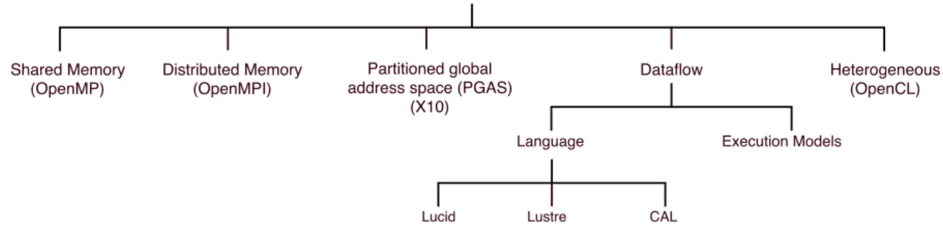
programming languages are control driven, and dataflow programming languages are mainly data driven. The available programming models can be broadly classified into five groups. They are: i) shared memory based programming model, ii) distributed
memory based programming model, iii) partitioned global address space (PGAS) pro-gramming model, iv) dataflow propro-gramming model and v) heterogeneous propro-gramming model (displayed in the Figure 2.3). Until now, the most popular program execution
Figure 2.3: Programming models classification
models are based on von Neumann architecture. Due to its limitations (such as mem-ory latency, synchronisation) [I+88], dataflow model of computation has gained pop-ularity. However, the roots of the dataflow execution model date back to the early 1970’s. Dataflow [Den80, Den86] is an asynchronous as well as synchronous [KGA01] distributed computation model. Dataflow threads are set of synchronised and sched-uled instructions. It can support non-preemptive execution, but the compiler controls thread granularity. In general, dataflow model can be classified either as static [DM75] or dynamic [GKW85]. Applications adhering to such program execution models (PXMs) follow producer-consumer model, which offers a natural way for synchronising parallel activities. By allowing threads to schedule the execution of other consumer threads, the synchronisation mechanism set to the required number of input data to an appropri-ate consumer thread. The dynamic form of dataflow can support a higher level of par-allelism by supporting repetitions [GP+77]. An application written based on dataflow
language creates a directed acyclic graph (DAG). In DAG, each node represents a thread, and the arc is the data path to other threads. Computation occurred when the needed data arrived at the nodes, and dependent threads will not resume until their data ar-rives at the nodes via the arcs. All the nodes that have input data available can im-mediately start their execution. In this doctoral work, the employed dataflow threads exhibit some features such as i) a dataflow thread triggers its execution only when all input data are available, ii) it does not support any jump, iii) simultaneous read-write is not permitted, and iv) supports shared memory model. During the execution, a dataflow thread can have any one of the following states:
• Waiting: when all the inputs are not available.
• Execution: thread is assigned to a specific core for its execution.
Yazdanpanah et al. in their paper [YAMJGE14] classify hybrid dataflow/von-Neumann models compared to block level execution model, control and dataflow execution models. Nowatzki et al. in their work [NGS15] claim that dataflow model can achieve good per-formance by reducing energy up to 40%. In this paper, authors also argued that if a core provides support for both dataflow and out-of-order execution mode, then applications can achieve better performance at lower cost (by automatically switching from one mode to another).
2.1.1 Dataflow execution model
Unlike conventional control driven execution, in the dataflow execution a DAG is used to represent the data dependencies among the threads. It allows the consumer thread to run once all the required inputs are available. This way of triggering the execu-tion helps to exploit the TLP because it reduces the amount of traffic generated by the synchronisation activities on multicores. Dataflow-based PXMs offer a lower syn-chronisation cost with a better use of processor resources. Hardware support for such PXMs are implemented in various early architectures ([CGSVE95, N+90]). Both High-Performance Computing (HPC) and High Throughput Computing (HTC) applications, as well as Cloud Computing, can significantly benefit from the adoption of dataflow PXMs. Some dataflow based PXMs are: DF-Threads [GF14], Codelets [SZG13], Data triggered threads (DTT) [TT14, TT12, TT11], Data driven multithreading (DDM) [KET06] and Scheduled Dataflow (SDF) [KGA01].
• DF-Threads is a variant of dynamic dataflow that can be easily interfaced to li-braries and hardware implementations.
• Codelet is a fine-grained dataflow model for supporting multiple nodes connected via an interconnection subsystem. A codelet represents a non-preemptive, single unit of computation. Codelet relies on an abstract machine model (AMM). It pro-vides an abstraction of the features which is required by the hardware processors to support the thread execution. The two levels adopted in the Codelet model al-lows better use of the data principle of locality. For efficient execution, multiple codelets are connected to form a codelet graph (CDG).
• Data triggered threads (DTT) proposed a dataflow-inspired execution model called data-triggered thread execution. It has been suggested for CMP and SMT domain. Software supports for DTT can run on any parallel machines. CDTT is a compiler framework which supports C/C++ and generates data-triggered thread executable (which can run by the runtime). It adds four new instructions for runtime support
and an extra hardware support for house-keeping jobs. DTT tries to exploit the redundant computation to speed up the execution.
• Data-driven multi-threading (DDM) execution model has inherited data availabil-ity based on execution feature from dynamic dataflow model (more precisely from decoupled data-driven (D3) graphs [EG90]). In DDM, applications are partitioned into a data-driven synchronisation graph and threads at the compile time. DDM effectively separates threads that are data dependent and independent. DDM model requires storing the application dataflow graph (DFG) locally to select ready threads and scheduling new ones. Similar to conventional dataflow, this non-blocking mode of execution is another way to hide synchronisation and commu-nication latencies by running other independent threads in a shared memory ad-dress space.
• Scheduled dataflow (SDF) architecture represents a decoupled memory/execution implementable on multithreaded architecture using non-blocking dataflow threads. Both SDF and Codelet supports self-scheduling property where it is not required to store the application DFG, and the threads are dynamically scheduled at run-time. However, the Codelet model differs from the SDF for the hierarchical organ-isation of the threads.
Recently some of these PXMs also receive some hardware supports ([STE06, TT11, GS15]).
2.1.2 Dataflow languages
Some of the well-known dataflow languages are Lucid [AW77], Lustre [HCRP91], actor model based (such as CAL [EJ03]) (see figure 2.3).
• Lucid programming language is a non-procedural/functional language. Dataflow computation can be achieved using its temporal operators. In Lucid code, the statements are mainly equations. It is described in such a way so that a calcula-tion of racalcula-tional numbers can be done.
• Similar to Lucid, Lustre is also an another functional language. It is a syn-chronous dataflow programming language. The Lustre code has three main parts: clocks, flows and nodes. The code can be compiled to multiple target languages (such as C).
• CAL is a dataflow-inspired actor based programming language. CAL describes modular, non-shared dataflow components called Actors. Actors are threads run-ning C or C++ language and can communicate with thread-safe software FIFO
buffers. The FIFO’s are protected by the mutex, but it suffers from high latency issues. Actors only can communicate via I/O ports. Actor intakes token, changes its state and produces another token. During execution, CAL produces a network of actors. Reading a thread will suspend until a producer thread does not produce all needed tokens/inputs for input port (data-driven approach).
2.2 Hardware overview
Today’s HPC applications have two main requirements: i) higher performance and ii) better energy efficiency. In recent years due to the immense growth in silicon industry, the microarchitecture also started to become complex and powerful (e.g., the prototype of a Kilocore which connects 1024 cores in a single system [BSP+16b]). The changes can mostly be grouped into two classes: increased core count (lead to multicore and now manycore chips), and different processing capability fused inside a single die (hetero-geneity). The increased core count provide immense computing power and to support them multiple programming models also started to develop. The system with increased core counts are also known as accelerator or co-processor (such as Intel Xeon-Phi). How-ever, in recent time, building low powered single board computer with very good amount of computational power is getting popular, and few of them are Parallela, Kalray’s MPPA 256. The growth in core count will help to share the chip area and resources to run mul-tiple applications concurrently but the concurrent execution of mulmul-tiple threads will immensely stress the system. So proper resource management together with heat re-moval mechanism must be incorporated into the system. In this section, the discussions will be focused on some (co)-processors which either supports control-driven execution or data-driven execution.
2.2.1 Hardware support for control-driven execution
2.2.1.1 Intel Xeon-Phi co-processor
Many integrated core (MIC) architecture is an HPC accelerator built upon X86 archi-tecture and manufactured using 22-nanometer lithography. Xeon Phi has processor cores that can run its own operating system. Each core has an L1 cache (of 32 KB for data and instruction), L2 cache (of 512 KB for both instruction and data) but not L3 cache. All L2 cache have their tag directories and translation lookaside buffers (TLBs). These distributed tag directories are used to provide uniform access and to track cache lines in all L2 caches. It supports MESI (Modified-Exclusive-Shared-Invalid) protocol for cache coherency and memory coherency. Each core is multithreaded (up to four threads)
and follows in-order execution. Cores are interconnected by a bidirectional ring topol-ogy (dual-ring). MIC supports single instruction, multiple data (SIMD) taxonomy and also supports specialised SIMD instruction sets (such as advanced encryption standard new instructions (AES-NI), MMX, or streaming SIMD extensions (SSE) (extension of MMX)). Apart from that, the accelerator card only understands X87 instructions. Phi micro-architecture is based on scalar pipeline and vector processing. Each core has a dedicated 512-bit wide vector floating point unit (VPU) and is crucial for the higher per-formance. It also supports fused multiply-add (FMA) operations. If FMA is not used, then performance will be turned to half. Each core can execute two instructions (one on U-Pipe and another on V-Pipe) in its core pipeline in every clock cycle. Only one floating point or vector instruction can be executed in any one cycle. The instruction decoder is a two-cycle unit and hence, at least two threads are needed to attain maximum core utilisation.
Recently, commercial manufacturing of single board computers with multicore chips and an accelerator (on the same circuit board) have started. Below two are the example of such systems.
2.2.1.2 Parallella
Parallella [Ada13] is a scalable, open-source, superscalar, RISC (Reduced instruction set computing) based manycore architecture which relies on MIMD (multiple instructions, multiple data)-based execution model. It provides scalability and low power consump-tion (e.g., using 5 volts 16-core based Parallella board can attain 32 GFLOPS as peak performance). Parallella is based on Epiphany system-on-chip (SoC) that wraps Zynq with dual-core ARM Cortex-A9 as host processing core. ARM cores have its kernel and follow master-slave execution model. The Epiphany architecture has been designed to extend the floating point computing power with very low energy consumption. Each co-processor is of 32-bit wide with the max clock speed of 1 GHz (average 500 to 600 MHz) and has variable-length instruction pipeline. Each core mainly has six components one each for integer operation, floating point operation, 64-bit general purpose registers, program sequencer, interrupt controller and debugging unit. Similarly, to Xeon Phi, it also supports FMA operations and can perform two floating point operations at ev-ery clock cycle. Parallella supports 32-bit wide little-endian based flat shared-memory architecture, and each core has unprotected, a local memory (both for data and instruc-tion) of size 32KB that are further divided into four sub-banks. Each co-processor has a unique global address and can transfer 8-bytes of data or instructions at every clock cycle. Each core connected by 2D low-latency NoC. It provides three lines for reading and two for writing (one for off-chip and on-chip) operations. It is based on ANSI-C/C++ and OpenCL programming environments. The read operations are non-blocking and the
read-write operation for local memory follows strong memory model, but the read-write operation for non-local memory does not follow any strict order execution. However, memory constraints and memory access issue (such as concurrency or memory quirks) are big problems for it’s performance in real applications.
2.2.1.3 MPPA-256 processor
Kalray’s MPPA-256 is a multi-purpose processor array (MPPA) based single-chip many-core processor that is built using 28nm CMOS lithography [dDdML+13]. The MPPA
includes quad-core CPUs coupled with the manycores. Each MPPA core is based on a 32-bit very long instruction word (VLIW) architecture and also comes with an FMA func-tionality. Each core has it’s L1 instruction and data cache. It wraps 256 processing cores and 32 system cores on a chip (thus many counts total 288 cores). Each compute cluster consists of 16 identical cores with own standard FPU and memory management unit (MMU). The cluster cores work non-preemptively, which is ideal for very specialised computation, but not suitable for the high-level application. This MPPA architecture consists of an array of clusters linked by two 2D torus-based NoC (one for data move-ment and the other for control). The NoC provides a full duplex communication between clusters and a lightweight POSIX kernel is running inside each cluster. In every clock cycle, it can support up to five 32-bit RISC-like integer operations. The processing cores in the array used their local memories and dedicated DMA to perform their global mem-ory addressing. It seamlessly supports C based dataflow and pthread based execution models and is also well-suited for applications such as image, audio, signal processing.
2.2.2 Hardware support for dataflow execution
The hardware support for dataflow execution has started from early 1990’s. Dataflow inspired architectures are meant to offer low cost, efficient and flexible platform for dataflow computational model. Dataflow approach can offer the highest level of paral-lelism if the application has a huge number of concurrent independent threads. The dataflow systems support both static and dynamic dataflow based execution and also the explicit token-store architecture (such as Monsoon). Few known dataflow supported hardware are Monsoon [PC90], Efficient Architecture for Running THreads (EARTH) [The99], WaveScalar [SMSO03] and the latest Maxeler processing platform [PL13].
2.2.2.1 Monsoon
Monsoon is an explicit token-store (ETS) based architecture prototype for dataflow based execution. In ETS architecture, token carry pointers and each token descriptors are ad-dressed in a global memory which is partitioned among the cores. In Monsoon, each
core supports the eight-stage pipeline. In instruction fetch (IF) stage, an explicit token address is computed from the frame address and an offset. Next, the availability of the operands is checked. When data arrived, it is stored in the frame slot of the frame memory. When all the data arrived, the execution stage starts.
2.2.2.2 WaveScalar
WaveScalar is a tile-based processor architecture for executing conventional pthreads, and also dataflow threads. To support multithreading, WaveScalar extended its instruc-tion set. Its thread spawning mechanism tries to parallelize small loops inside the ap-plication. WaveScalar supports threads that do not have their stack and cannot make functions call but has it’s thread identification. WaveScalar provides each thread with a consistent memory view and lets application to manage the memory ordering directly. To support the concurrent thread execution, it supports multiple, independent sequence of ordered memory access.
2.2.2.3 Efficient Architecture for Running THreads (EARTH)
EARTH belongs to the group of hybrid dataflow/von Neumann execution model. The PXM of EARTH was customised to support dataflow threads. For efficient runtime ex-ecution, programs are divided into threaded procedure (similar to functions, but differ on frame allocation, thread invocation, scheduling and parameter passing) and fiber. Fiber supports three states during its lifecycle such as enabled, active, and dormant. Fiber supports sequential execution of its instruction sets and non-preemptive execu-tion. When a thread is ready, the system enables the fiber, and it executes the threaded procedure. Procedures are invoked automatically by the application but can be ter-minated explicitly. After invoking the procedure, the system creates a context for the procedure and executes other housekeeping jobs. Finally, when execution is complete, fiber is removed from the processor, but the associated threaded procedure may stay alive.
2.2.2.4 Maxeler
Maxeler is an FPGA-based platform which could be a promising candidate for accelerat-ing the HPC applications. It is a combination of synchronous dataflow, vector, and array processors. This platform has PCIe-based connectors to connect X86 processors, and FPGA to offload the task. The Maxeler ecosystem maps the application on the FPGA using static graph. Maxeler processing platform comprises of multiple dataflow engines (DFEs) with their local memories connected to the host CPU via interconnect. Multiple DFEs are linked by a high-bandwidth interconnect called MaxRing. DFEs execute the
tasks in a dataflow fashion and supports both fast and large memory. DFE can manage one or multiple kernels (for main execution) and a manager for data movement within DFEs. Maxeler has its compiler to generate dataflow implementations which can then be called from the CPU via a special interface called SLiC (Simple Live CPU). Together with the compiler, it also has it’s software middleware between the Linux and DFEs for runtime data transfer and optimisation. Maxeler is an FPGA-based accelerator which comes with it’s programming methodology to help to develop a customised energy effi-cient (runtime) system.
2.2.2.5 Transport Triggered processor
Transport triggered processors (TTPs) are mainly based on the scalable transport trig-gered architectures (TTAs) where operations occur as side effects of data movements [Cor97]. TTP is an evolution of VLIW processor while TTP directly sends data from one fetch unit (FU) to another without involving the registers or memory [Cor94]. TTPs (are of single instruction multiple transports type) support ILP and can also be used as application-specific architectures. Unlike others, TTAs do not include any instruction set. Thus the programmer defines the data movements between FUs. The memory access speed in TTP is low, and data transport defines the cycle time of the processor. Adding new FU to TTA is easy, in turn, addition also linearly increases the complexity.
2.2.3 Heterogeneity
Increased core count does not only offer a higher number of cores but also pose chal-lenges (such as concurrent programming issues, controlled power consumption, and improved scalability). The heterogeneous system architecture (HSA) is an approach where it tries to achieve better parallelism using low-power cores with different capa-bilities [KFJ+03]. Asymmetric CMPs (ACMPs) [SPS+07, KTJR05] are one of the first
successful approaches to embed heterogeneity into the CMPs. The heterogeneity does not only improve the power but may also successfully satisfy the application require-ment. Generally, ACMPs contain one or multiple large, powerful, out-of-order cores and also few small, simple and power efficient cores on the same die. ACMPs can effectively accelerate both fine grains and coarse grain thread execution.
A popular heterogeneous computing model is created when a host processor (such as general purpose core) combines with an accelerator (such Xeon Phi). In this ecosystem, host CPU works as a master while Xeon Phi is used as an accelerator to speed up the whole process (slave). However, the offloading cost of computation must be computed before initiating the task off-loading. Based on the amount of task, the offloading may
become costly. Super computer (such as Tianhe-2) is also built upon CPU-Xeon Phi ecosystem.
Commercial product such as ARM’s heterogeneous multicore big.LITTLE [ARM13] is another example of multicore ACMPs. It wraps a powerful application processor (Cortex-A15) with simpler cores (Cortex-A7). This architecture gives a trade-off between high performance and low power consumption. To schedule the jobs on these cores, two possible ways are CPU migration and task migration. In CPU migration, processes are mapped first on the simpler core and later moved to a larger core. In real time execu-tion, the scheduler only sees one logical core for each set of big.LITTLE cores. However, in task migration, all the cores are exposed to the scheduler. The main task started to execute on the bigger core and simpler tasks are performed on the simpler cores. The cost of migration between core happens only at a coarse granularity. In general, the energy consumed by an instruction is partially related to the number of pipeline stages it traverses.
2.2.3.1 FPGA
Field-Programmable Gate Arrays (FPGAs) offer a quick prototype of hardware designs and also re-designing features via reconfiguration capabilities. FPGAs can be pro-grammed via various ways such as high-level synthesis (HLS), circuit schematics or by using a hardware description languages (such as VHDL, Verilog).
The two most important components of FPGA are configurable logic blocks (CLBs) or logic array block (LAB) and look-up-tables (LUTs). Every CLB consists of multiple LUTs, a configurable switch matrix, selection circuitry (MUX), registers and flip-flops (FFs). LUT is nothing but a hardware implementation of a truth table. LUTs are used to implement any arbitrarily defined Boolean functions in CLBs. LUTs are also used as small memories or small RAM. In general, there exist two types of FPGA: one-time programmable (OTP) FPGAs and widely used SRAM-based (can be reprogrammed as the design evolves). SRAM blocks are interspersed in the fabric and can be chained together to build deeper wider memories or RAMs. For processing data, FPGA also has hard IPs (such as a multiplier, DSP, processors–e.g., ARM Cortex-A9 dual-core MCU is used in Zynq-7000 SoC from Xilinx). Apart from that, there is also software-based core or softcore which can be a simple microcontroller or a full-fledged microprocessor. It has less clock speed compared to hard IPs. However, it can be easily modified and tuned to specific requirements, custom instructions (e.g., OpenRISC is a softcore). For a faster communication, FPGA also offers high-speed serial I/Os and all state-of-the-art FPGAs incorporate multi-gigabit transceivers (MGTs) for very high-speed communication.
2.3 Interconnection subsystem
Broadly, the research topics discussed in [SC13, MOP+09, OHM05] could be
classi-fied into multiple research streams: (i) microarchitectural domain (mainly deals with network topology, architecture, capacity management); (ii) the communication infras-tructure (mainly proposing the models, switching techniques, congestion control, power management, fault tolerance); (iii) analytical methods for evaluating proposed NoC’s performance; and (iv) mapping applications on the processing core.
For large core counts, NoC is a critical component responsible for better performance. NoC’s architectural components such as channel width, buffer size, routing algorithms are very critical for better flow of the data packets inside the chip. Latency improve-ment, hotspot mitigation or deadlock free traffic movements are the main research is-sues in interconnection subsystem. During thread execution, all the core communica-tion and the data transfer is done using interconneccommunica-tion subsystem. Inside the chip, last-level caches (LLCs), the bandwidth of interconnect as well as memory have become very critical for better performance. For better throughput and lower latency, the on-chip interconnect bandwidth should be high. Inefficient interconnection subsystem may lead to reducing the overall system performance and consume a significant portion of the area and power budget of the chip [HVS+07].
Apart from that, application mapping on manycore processors is not easy when per-formance constraints (such as power consumptions, latency, throughput) must be satis-fied. Multiple processing cores are connected by NoC, which provides the shared commu-nication medium for information exchange. Typically, a processing core of a tiled CMP consists of first level cache, last level cache, a network interface (NIC) and a router. The NIC manages the cache level information and breaks the information into the flow control units. Next, the messages are composed of one or multiple packets. The ele-ments that mainly characterise a NoC are the topology, routing algorithm, flow control, and crossbar based router microarchitecture. Below we are describing them in brief (for more details, please refer to [DT04a]).
2.3.1 Topology
A key aspect of NoC-based interconnections is the topology, i.e., the way routers are con-nected to each other. The topology mainly describes the floor planning of routers to use the interconnect subsystem efficiently. It defines the hop count to refer to physical im-mediacy between the cores; more the hop count higher the latency for the packets are. The interconnection subsystem does not only connect cores, but also other functional components such as LLC, memory and DMA controller. Hierarchical or hybrid
topolo-gies started getting introduced, when designers started to face performance challenges for connecting multiple cores using simple topologies (such as bus or ring). In general, some of the well-known topologies are bus, ring, 2D-mesh, torus, flattened butterfly (discussed below (see figure 2.4)).
Figure 2.4: Some well-known topology for interconnect subsystem
• Bus topology is a simple, inexpensive topology that connects cores along a sin-gle connection wire. Ethernet 10Base2 was a practical example of the first bus topology in action. However, the bus topology started to suffer from high energy consumption, low scalability, and low bandwidth for connecting a large number of processing cores. The main reason was the physical capacitance of bus wires
which started to grow with the number of connected modules, thus resulting in a growing wire delay.
• Ring topology connects multiple cores along a single wire in such a way it forms a closed loop. The ring topology is also a simple and inexpensive topology. It can continue to serve increased core count after exceeding its capacity but with slow speed. In general, scaling up or down the ring capacity can affect the network service. Similarly, for the ring, the average latency started to increase with the proportional number of cores inside the chip and making the bandwidth a poten-tial bottleneck.
• In direct topology, cores are connected in a two-dimensional space. This kind of organisation helps to remove the routing overheads with increased core counts us-ing the low radix routers. The 2D-mesh is an example of direct network topologies. In a 2D-mesh, all the core connecting wire length are equal in length. Thus the area and power consumption grow as the number of connecting core grows.
• Similar to the 2D-mesh, a 2D-torus is an another example of direct topology. Torus is also known as k-ary n-cube. It means that k number of cores can be connected in the n-dimensional space (in each dimension). It is interesting to note that ring is an example of one dimensional torus. Unlike 2D-mesh, the 2D-torus can lead to higher latency because the each edge cores are further connected to routers of the opposite edge via wrap around wires. This feature has alleviated in folded 2D-torus where the wires are of the same length.
• Concentrated mesh or C-Mesh network [BD06] is a modification of 2D-mesh to a radix-4 mesh where each router maintains four processing core of the network. It helps to reduce the latency (hops) proportional to the concentration degree of the network, while providing few number of channels with higher bandwidth. The C-Mesh network uses dimension-order routing with the express links for packet transfer.
• Flattened butterfly [KBD07] is another improved layout of mesh to reduce the la-tency for better communication among the cores. It is based on the high-radix routers (radix=10) and non-minimal global adaptive routing. It provides a maxi-mum of two hops but with longer wires. Though the longer wire increases cost, it also provides a better way to store temporary packets intermediately.
For smaller core count, topologies such as bus, ring were very popular, but as the core counts inside the chip started to increase we need newer topologies such as the C-Mesh or flattened butterfly. However, for very high core counts hierarchical topologies
Figure 2.5: XY DoR routing direction (left) and block diagram of a mesh router architecture is presented (right)
have also been proposed (such as bus and 2D-mesh based [DEM+09], mesh and ring based [AFY+16] are few of them).
2.3.2 Routing
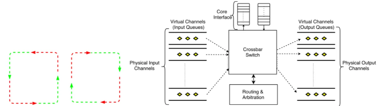
The routing algorithm selects the links that a packet must follow to reach its destination from the source. Two most common class of routing algorithms for NoC are adaptive routing algorithm and deterministic routing algorithm. In adaptive routing, packets are moved from source to destination using different links. However, when the links are busy, different links can be selected based on user defined metrics. A cyclic link is not created to avoid deadlocks. In the deterministic scheme, the same set of paths is always selected for the same set of source and destination cores. In this work, the XY dimension-ordered routing (XY DoR) (see figure 2.5 (left)) has been used. In this routing scheme, all the packets always traverse first in the X direction (i.e., east or west) and then turns towards Y direction (i.e., north or south) in the figure red colour is the forbidden path, and green colour shows the allowed path.
2.3.2.1 Flow control
Flow control (FC) controls the flow of packet by allowing it to flow along its allowed path and also to stay temporary in some buffers when the link is busy. FC optimises the packet latencies and also the throughput at higher loads. It works in close collaboration with the routing scheme to make sure that packets reach its destination. There are two types of flow control policy: circuit switching and packet switching. In this work, packet switching has been used. The packet switching follows store and forward mechanism. In this policy, resources are allocated to the whole packet. The entire packet is stored before forwarding to the next link. It can increase latencies when packet consists of multiple flits. Packet-switched flow control can be classified into store-and-forward (used in this
work), virtual cut-through and wormhole (mainly for flits) which are further explained in short below.
• As the name suggests, in store-and-forward (SAF) flow control, an entire packet must be received completely in the router before being forwarded to next router. For efficient storing, buffers and link bandwidth are allocated for the packet (based on packet size). It offers higher per-hop latency, but still, large buffers are needed for large packet size.
• Unlike SAF, virtual cut-through (VCT) flow control reduces per-hop latency for large packets but still need large buffers. It reduces the per-hop serialisation delay by forwarding some flits of a packet before receiving all flits of the packet.
• Wormhole flow control mainly works at flit level granularity. It is an improved control mechanism compared to SAF and VCT. Similar to VCT, it allows the flits serially to move to the next router given there is a space for it to store. It improves the buffer utilisation but suffers from the head of line (HOL) blocking. HOL refers to the problem where a flit of a packet at the FIFO queue gets blocked due to the congestion at its next router, then other packets behind it also get blocked.
2.3.3 Router microarchitecture
A basic microarchitecture of a crossbar switch based mesh router has been shown in figure 2.5 (right). The input channels of a mesh router have input buffers. Each input channel connects to a crossbar switch and then connect to any output channel. The in-put buffers consist of multiple virtual channels (VCs). In general, routers are pipelined to improve the packet latency. Logic (router wraps I/O ports, route compute unit, an arbitration logic, and VC status table) are used at every step to make sure that packet arrives at it’s destination based on the header information. There are three main oper-ations performed by the router. They are route computation, switch allocation (SA) and VC allocation (VCA).
In route computation, the packets are routed based on the routing algorithm. In SA process, packets are arbitrated to access the crossbar switch. It is mainly a mapping is-sue between the VCs of the router to the free output port of the router. VCA makes sure that the whole packet gets a VC at the next router. Round-robin arbitration is widely used arbiter and has been used in this work because it provides better fairness. Allo-cator maps incoming requests to available resources (VCs and crossbar switch ports), while arbiter matches requests to a single free resource.
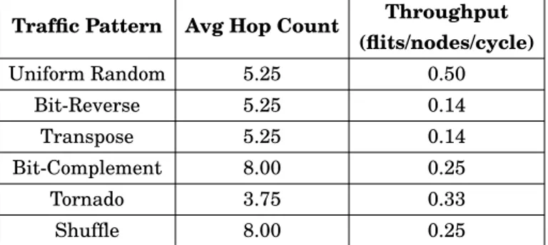
Table 2.1: Theoretical performance of 8x8 mesh for six synthetic traffic patterns
Traffic Pattern Avg Hop Count Throughput
(flits/nodes/cycle) Uniform Random 5.25 0.50 Bit-Reverse 5.25 0.14 Transpose 5.25 0.14 Bit-Complement 8.00 0.25 Tornado 3.75 0.33 Shuffle 8.00 0.25 2.3.3.1 Traffic patterns
There are six well-knows traffic patterns to represent the real-time application’s traffic behaviour. The patterns, their theoretical latency (average hop count) and theoretical throughput for 8x8 mesh router using with XY-DoR routing are presented in table 2.1. It is worth to note that the injection rate was one packet per cycle (worst case scenario). From the table, we can see that the mesh has performed best in the uniform random traffic pattern, but uniform random traffic pattern does not identify the load imbalance of the design because in this pattern every source with equal probability can send pack-ets to every destination. Hence it is always recommended to analyse the design using multiple traffic pattern. In this work, first three traffic patterns are used.
2.3.4 Hybrid NoC architectures
In the past years, NoCs received much attention from the research community [ODH+07, BM06a]. Where some of the works focused on proposing low latency router microarchi-tectures ([KPKJ07, HVS+07]) and power efficient microarchitectures ([WPM03, MCM+04]), other researchers focused on proposing different topologies. For instance, Dragonfly [KDSA08] and Flattened butterfly [KBD07] are few among others. Other works (such as [AFY+16, DEM+09, BZ07]) tried to improve the performance-power consumption trade-off through the introduction of hierarchical NoC topologies.
2.3.4.1 Ring and mesh-based approaches
HiRD [AFY+16] is a hierarchical ring-based NoC design for improved energy efficiency, where buffers within individual rings are not used. It provides buffer support between different levels of the ring hierarchy, and upon the saturation of buffers, flits are de-flected in the rings. It needs four levels of hierarchy to connect 256 PEs. CSquare [ZGHC15] proposes a way of clustering routers so that clusters adopt an internal tree-like organi-sation. It is a topology with clusters forming a global parallel structure to provide high