A
A
l
l
m
m
a
a
M
M
a
a
t
t
e
e
r
r
S
S
t
t
u
u
d
d
i
i
o
o
r
r
u
u
m
m
–
–
U
U
n
n
i
i
v
v
e
e
r
r
s
s
i
i
t
t
à
à
d
d
i
i
B
B
o
o
l
l
o
o
g
g
n
n
a
a
RESEARCH DOCTORATE IN
Mechanics and Engineering Advanced Sciences - Project n° 2:
“Fluid Machines and Energy Systems Engineering”
Cycle XXV
Affiliation sector: 09/C1
Scientific-disciplinary sector: ING-IND/08
PhD Thesis title
Theoretical and Experimental Analysis
of
micro-CHP Energy Systems
Presented by: Dr. Eng. Roberta Vecci
PhD School Coordinator:
Supervisor:
Chiar.mo Prof. Ing. Chiar.mo Prof. Ing.
Vincenzo Parenti Castelli Michele Bianchi
A
A
l
l
m
m
a
a
M
M
a
a
t
t
e
e
r
r
S
S
t
t
u
u
d
d
i
i
o
o
r
r
u
u
m
m
–
–
U
U
n
n
i
i
v
v
e
e
r
r
s
s
i
i
t
t
à
à
d
d
i
i
B
B
o
o
l
l
o
o
g
g
n
n
a
a
DOTTORATO DI RICERCA IN
Meccanica e Scienze Avanzate dell'Ingegneria –
Progetto n° 2: “Ingegneria delle Macchine e dei Sistemi
Energetici”
Ciclo XXV
Settore Concorsuale di afferenza: 09/C1 Settore Scientifico disciplinare: ING-IND/08
TITOLO TESI
Analisi teorico-sperimentale
di
Sistemi Energetici micro-Cogenerativi
Presentata da: Dott.ssa Ing. Roberta Vecci
Coordinatore Dottorato:
Relatore:
Chiar.mo Prof. Ing. Chiar.mo Prof. Ing.
Vincenzo Parenti Castelli Michele Bianchi
To my daughter, Alissa
who has endured with patience my choice and
who encourages me to pursue my dreams, every day.
ACKNOWLEDGMENTS
My thanks to my superiors for welcoming me into their group giving me the opportunity to realize my dream.
My thanks to Professor Giorgio Negri di Montenegro, my professor during the degree years, for whom I have profound respect.
My thanks are to my supervisor, Professor Michele Bianchi, my guide, for his precious teachings and advice.
A sincere thanks to Professor Antonio Peretto, for the total trust he has given me during all these years.
Finally, a thanks are due to laboratory technicians, Mr. Tarì and, especially, Mr. Stefano Benaglia, for their help and total disponibility.
And above all
My heartfelt thanks go to my parents, and to two special persons who always walked to my side "for better or for worse" during all these years.
INTRODUCTION
The micro-CHP (Combined Heat and Power) energy systems, using renewable energy sources are an excellent response to the current issues of environmental impact. Producing, in combined and efficient mode, electricity and heat at low temperature directly on-site, using plants of size less than 50 kWel, they, especially for stationary applications in residential and small industries, represent the realization the energy Distributed Generation (GD) concept, an important strategy in the production scenario in the medium term.
Following this idea, the Ph.D. activity has pursued the aim of conceptual development and subsequent implementation of an Integrated Energy System (IES), capable of meeting the energy requirements and thermal properties of specific users, using different types of fuel, with the integration of electric generators in Renewable Energy Sources (RES), and electric and thermal accumulation systems, totally controlled by an automatic management control system.
To this end, in the first doctoral years the study of micro-CHP energy systems components, such as the combustion chambers of Micro Gas Tturbines (MGT), reactors, and pyrolyzer for the production of syngas from scrap tires has been addressed.
Specifically, the thermo-fluid dynamics (CFD) numerical analysis activity of MGT combustion chambers was carried out, evaluating turbulence and combustion models, and also by defining chemical kinetics mechanisms valid for the combustion of syngas, biogas and natural gas. Finally, the validation of the results obtained through the comparison with the experimental data has been made (De
Pascale, M.Fussi, A.Peretto, R.Vecci, "Numerical investigation of a swirled flame model combustor fed with pyrolysis gas," ECOS 2011 - The 24th International
Conference on Efficiency, Cost, Optimization, Simulation and Environmental Impact of Energy Systems, Novi Sad - Serbia, July 4-7, 2011., - M. Fussi, R.Vecci, 'potential' of renewable fuels "low-Btu" gas turbine "- The search there and you see - Palazzo D'Accursio-Bologna, 28-29 May 2010, Poster).
The need to environmentally recover scrap tires has led to the study (using three-dimensional CFD codes), the design and the definition of the control methods of a pyrolysis pilot plant. The plant is pending patents definition.
Having the availability of a Polymeric Exchange Membrane Fuel Cells (PEMFC), the coupling of which with an electrochemical storage system was developed and tested in a previous Ph.D. activity, at the DIN’s (previously DIEM) laboratory, the research has continued with the implementation of the conceptually conceived Integrated Energy System (IES).
After having built the system, the attention has been focused on the energy source of the above system, a 5 kWel PEMFC, on which numerous experimental campaigns for determining the PEMFC system electrical performance (polarization curve, powers, efficiencies of the fuel cell system) and CHP performance (thermal power, optimum cooling system temperatures, heat exchange with users, efficiencies), under different operating conditions.
Furthermore, the degradation mechanisms of the PEMFC system, in particular due to the flooding of the anodic side, have been assessed.
The analysis of the effect of the water management of the anodic exhaust at variable FC loads has been carried out, and the purge process programming logic was optimized, leading also to the determination of the optimal flooding times by varying the AC FC power delivered by the cell.
Then, for the analysis of the fuel (hydrogen, H2) utilization factor, an algorithm
for its calculation from the experimental data, able to determine the amount of not-reacted H2 and, therefore, the causes which produce the loss has been developed.
The algorithm considers the FC like a black box, so it doesn’t need access to its internal component and can be applied during the normal FC lifecycle. Through this algorithm the presence of the H2 crossover phenomenon was experimentally
Therefore, the ageing suffered by the FC system has been analyzed. An experimental tests campaign, comparing recent data with historical ones, was carried out to verify the aging suffered by the cell, the components involved and their main causes.
This thesis is completely dedicated to the detailed description of the latter investigation, conducted on experimental IES realized. This study, joining together theoretical and conceptual realization of an idea and its exploration by innovative mean is, I think, by mechanical engineer "old-fashioned" as I am, the culmination of personal fulfillment from an engineering standpoint.
ABSTRACT
In the framework of the micro-CHP (Combined Heat and Power) energy systems and the Distributed Generation (GD) concept, an Integrated Energy System (IES) able to meet the energy and thermal requirements of specific users, using different types of fuel to feed several micro-CHP energy sources, with the integration of electric generators of renewable energy sources (RES), electrical and thermal storage systems and the control system was conceived and built. A 5 kWel Polymer Electrolyte Membrane Fuel Cell (PEMFC) has been studied. Using experimental data obtained from various measurement campaign, the electrical and CHP PEMFC system performance have been determinate.
The analysis of the effect of the water management of the anodic exhaust at variable FC loads has been carried out, and the purge process programming logic was optimized, leading also to the determination of the optimal flooding times by varying the AC FC power delivered by the cell.
Furthermore, the degradation mechanisms of the PEMFC system, in particular due to the flooding of the anodic side, have been assessed using an algorithm that considers the FC like a black box, and it is able to determine the amount of not-reacted H2 and, therefore, the causes which produce that.
Using experimental data that cover a two-year time span, the ageing suffered by the FC system has been tested and analyzed.
Keywords
TABLE OF CONTENTS
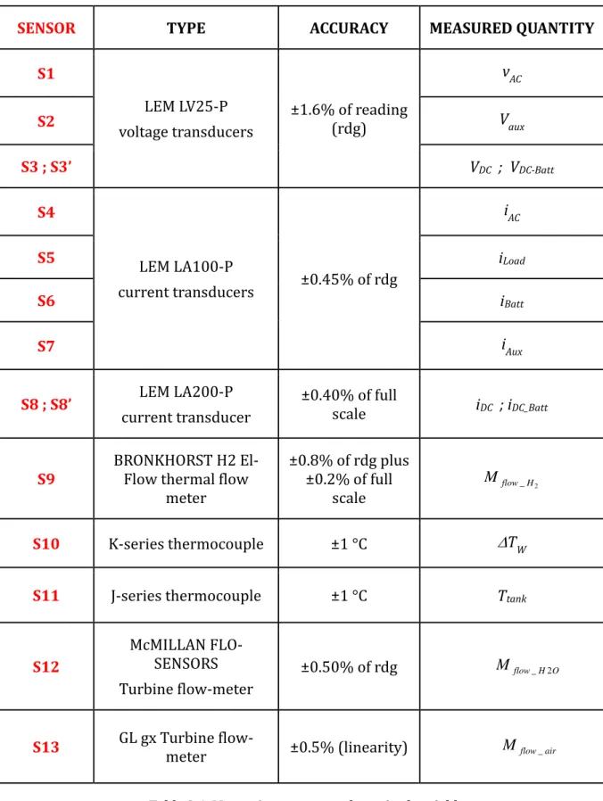
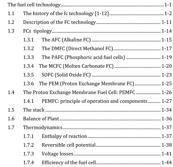
Nomenclature……….…………...i Introduction………vii 1. The fuel cell technology ... 1‐1 1.1 The history of the fc technology [1‐12] ... 1‐2 1.2 Description of the FC technology ... 1‐11 1.3 FCs tipology ... 1‐14 1.3.1 The AFC (Alkaline FC) ... 1‐15 1.3.2 The DMFC (Direct Methanol FC) ... 1‐17 1.3.3 The PAFC (Phosphoric acid fuel cells) ... 1‐19 1.3.4 The MCFC (Molten Carbonate FC) ... 1‐20 1.3.5 SOFC (Solid Oxide FC) ... 1‐23 1.3.6 The PEM (Proton Exchange Membrane FC) ... 1‐25 1.4 The Proton Exchange Membrane Fuel Cell: PEMFC ... 1‐26 1.4.1 PEMFC: principle of operation and components ... 1‐27 1.5 The stack ... 1‐34 1.6 Balance of Plant ... 1‐36 1.7 Thermodynamics ... 1‐37 1.7.1 Enthalpy of reaction ... 1‐37 1.7.2 Reversible cell potential ... 1‐38 1.7.3 Voltage losses ... 1‐41 1.7.4 Efficiency of the fuel cell ... 1‐441.7.5 Operating Condition: ... 1‐46 1.8 PEMC application and current status ... 1‐49 References to chapter 1 ... 1‐53 2. The Integrated Energy System ... 2‐1 2.1 The IES test system ... 2‐3 2.2 The components of the Integrated Energy System ... 2‐11 2.2.1 The fuel cell (FC) system ... 2‐11 2.2.2 The batteries and the bidirectional inverter... 2‐24 2.2.3 The photovoltaic (PV) emulator ... 2‐32 2.2.4 The electrical load ... 2‐34 2.2.5 The control system ... 2‐36 2.2.6 Sensors ... 2‐40 2.3 The IES operation states ... 2‐45 2.4 The FC operation programming logic ... 2‐50 References of the chapter 2 ... 2‐52 3. Experimental analysis of thr IES performance ... 3‐1 3.1 The acquired and calculated variables ... 3‐2 3.2 PEMFC performance analysis ... 3‐6 3.2.1 PEMFC electric performance analysis ... 3‐6 3.2.2 The FC thermal performance analysis ... 3‐28 References to the chapter 3 ... 3‐33 4. The degradation mechanisms of the PEMFC ... 4‐1 4.1 The main degradation mechanisms of the PEMFC stack components ... 4‐7 4.1.1 Chemical and/or physical effects ... 4‐8 4.1.2 Extreme external factors ... 4‐15 4.1.3 Poor water management ... 4‐18 4.2 Contamination of the PEMFC components ... 4‐25 4.3 Hydrogen crossover ... 4‐26 References to the chapter 4 ... 4‐32 5. Anodic exhaust management: analysis and optimization ... 5‐1
5.1 The hydrogen purging: motivation, limit and optimization strategies ... 5‐3 5.2 Experimental investigation on the effects of purging ... 5‐8 5.2.1 Piecewise model of the voltage drop due to flooding ... 5‐12 5.3 Optimized purging strategy ... 5‐14 5.3.1 Application of the optimized strategy ... 5‐16 5.4 Efficiency evaluation of the FC purge programming logic ... 5‐21 5.5 Analysis of the utilization coefficient ... 5‐27 5.5.1 Effect of the flooding duration ... 5‐27 5.5.2 Definition of the not‐reacted hydrogen fraction ... 5‐28 5.5.3 Algorithm for the evaluation of the not‐reacted hydrogen fraction ... 5‐30 5.5.4 Analysis of the efficiency using the fractions XDE and XA ... 5‐35 5.6 Experimental result ... 5‐38 5.6.1 Results of the 2010 tests (Old purge programming logic) ... 5‐39 5.6.2 Results of the 2012 tests (New purge programming logic) ... 5‐43 References to the chapter 5 ... 5‐56 6. Ageing of the PEMFC ... 6‐1 6.1 The FC ageing analysis ... 6‐3 References for Chapter 6 ... 6‐15 Conclusions………..c‐1
Nomenclature
Symbols
A active area
cw water specific heat
C capacity of the battery
E0 standard state reversible cell potential
Er reversible cell potential
Er,T actual cell voltage
F Faraday constant, F =96485 [C/mol]
f
h heat of formation of a reactant
i current
CROSS H
I 2 current induced by H2 crossed over
CROSS H
J 2 H2 crossover rate
K membrane gas permeability
PEM
l membrane thickness
m mass m& mass flow rate Mflow volume flow rate
mmol molecular weight
n number of electrons
Ncel number of fuel cells in the stack
p correction factor for grid losses
P electric power a H P 2 anodic side H 2 partial pressure Q thermal power
Qth recovered thermal power
Qav available thermal power
R universal gas constant
ROhm overall cell resi stance
RH Relative Humidity
T temperature
Tfl flooding time
ii
Tpu purge time
Uo air utilization factor
Uf fuel utilization factor
v,V voltage
Greeks
α slope of the straight line of the FC voltage
P
α activity of the products αR activity of the reactants
ΔE fuel chemical energy introduced into the FC ΔG Gibbs free-energy change
H
Δ enthalpy change ΔS entropy change
∆Tw CHP water temperature difference
a
V
Δ activation polarization
c
V
Δ mass transport or concentration losses
O
V
Δ Ohmic losses
ΔVfl FC voltage drop during the flooding time
ΔVmax maximum allowable FC voltage loss
ΔVp FC voltage drop during the purge time
ΔVrec FC voltage recovery after the OCV opening
PITM δ PITM location η efficiency θ electrolyte temperature PEM H2
ψ H2 membrane permeability coefficient ρ density
Acronyms and subscripts a anode
A refers to H2 not-reacted for other causes AC Alternate Current
AFC Alkaline FC air of the air
aux of the auxiliaries B blower
Batt of the battery BOL Beginnig Of Life BOP Balance Og Plant BP Bipolar Plates c cathode
CCP Combined Cooling and Power
cell refers to fuel cell
CHP Combined Heat and Power
CO / CO2 carbone monoxide /carbone dioxide
DPEM membrane diffusion coefficient
DC Direct Current DE dead end DM Diffusion Media
DMFC Direct Methanol Fuel Cell
DSP Digital Signal Processing
DV Directional Valve
el, ref reference value for electric production
EOL End Of Life FC Fuel Cell
f faradaic
fl flooding
FPGA Field-Programmable Gate Array
GD Distributed Generation GDL Gas Diffusion Layer GFC Gas Flow Channel GGH Gas-Gas Humidifier H2 (H2) hydrogen
H2O water
iv HX Heat eXchanger
HT High Temperature IES Integrated Energy System in inlet
id ideal
L Liter
LHV Lower Heating Value LT Low Temperature M through the FC membrane
MEA Membrane-Electrode Assembly mot motor
N Normal temperature and pressure conditions NR No-Reacted
MCFC Molten Carbonate FC O2 oxigen
OCV Outlet Control Valve
OLTC On-Load Tap-Changer transformer
out outlet P pump
PAFC Phosphoric Acid FC PEM Proton Exchange Membrane PES Primary Energy Saving
PID Proportional-Integral- Derivative controller
PMS Power Management System PRV Pressure Reducing Valve Pt platinum
PTFE PolytetraFluoroEthylene
PITM Platinumin-Into-The-Membrane
pu purge rec recovery
RES renewable energy source
s, (stack) of the stack S measuring Sensors SCV Safety Control Valve
SOC State Of Charge of the battery SOFC Solid Oxide FC
tank of the tank tot total
th, ref reference value for thermal production
vent loss due to the utilization factor
u output of PID controller
vii
INTRODUCTION
The electricity and heat energy consumption of residential and small businesses units is currently satisfied through the separate supply of electricity and heat. In fact, to date, this requirement is satisfied by a traditional model in which the electricity is generated in large power stations, far from the urban catchment area, and from there, transferred later to individual users through the complex transmission and distribution network.
The thermal energy, instead, is generated directly at the single user via combustion systems for space heating. The above model, although it is well established and tested, is still suffering from multiple disadvantages, in particular a low overall thermodynamic efficiency, not negligible pollutant emissions and the necessary presence of an electricity distribution network, onerous in terms of operating cost and investment. All of this leads to the end user a quite high cost of energy purchased
An alternative to the traditional model are networks of district heating (also named teleheating) which, fed by cogeneration plants, involving the combination of electrical energy production and heat and/or cold generation in a centralized manner. These networks, although solve most of the disadvantages listed above, are still ineffective in terms of pollutant emissions reduction but, most importantly, require a double network of electricity and thermal distribution and, therefore, high costs anyway. Recently is gradually emerging a new concept of energy generation (considered in its three forms: electricity, heat and cold), called " Distributed Generation" (GD), that involves the insertion, in metropolitan areas, of multiple high‐efficient micro‐cogenerative plants, able to satisfy a significant portion of the household, commercial and office buildings energy requirements (electrical, heating and air conditioning).
viii
The outstanding feature of the GD is the ability to combine the well‐known thermodynamic benefits of the cogeneration with high perspective performance of the most promising systems for micro‐Combined Heat and Power (CHP). This fact involves both a more rational use of the energy resources and a significant simplification of the infrastructure required for the energy conveyance.
In the context of the micro‐CHP energy systems, one of those currently most promising for residential uses are the fuel cells (FCs) ‐ based energy.
The fuel cell is an energy conversion device that converts the chemical energy of the fuel (typically hydrogen) directly into electrical energy without the need to go through a combustion process. In fact, because it uses a fuel without carbon atoms and sulfur emission pollutants such as CO, CO2, NOx and SOx and particulates and metals are not present. The only product of the FC is the 'water, originating from the oxidation of hydrogen.
The hydrogen, however, is not present in nature as a single molecule, but it is necessary to produce it. To date, despite the promotion of the development of clean technologies for hydrogen production (e.g. by algae or bacteria exploiting solar energy), unfortunately the most economically advantageous industrial systems are those that use fossil fuels as a fuel, in particular methane. Currently, the only alternative used is the electrolysis process, which through the electrolytic cell powered by direct current, allows the water molecule splitting into hydrogen and oxygen. Clearly, this alternative is only viable if the process used for the production of the electrical energy required for the process comes from renewable sources, such as biomass, hydropower, wind power and photovoltaic. Consequently, the massive diffusion of hydrogen will occur only when these sources will be economically competitive with conventional sources.
Nevertheless, nowadays, all industrialized countries are promoting "H2 economy", that is, a society based on the use of hydrogen and electricity seen as clean energy carriers, both derived from fossil fuels in the first development and from renewable (and possibly also by nuclear power) in a later and permanent phase.
ix The fuel cell is therefore a direct application of two highly topical issues in industrialized countries, i.e. the hydrogen as a potential fuel of the future to cope with the problems of air pollution, in particular the increase in greenhouse gases, and the scarcity of primary energy sources used up to now. In fact, although the extraction technologies and geology techniques for the discovery of new fields are in continuous development, the developing countries energy demands and the world's population are still strongly increasing. It is estimated that the population will amount to 8.5 billion in 2020 and 10 billion in 2050 (http://www.bp.com).
Therefore is in this context that the fuel cell (FC) energy systems are inserted. In fact, they have energy efficiency significantly higher than that of conventional systems. This property coupled with their different operating principle lead to a significant reduction of the amount of carbon dioxide (CO2) emitted, on equal power and heat products. The reduced local air pollutants emissions are also coupled to an extremely low noise level (less than 60 dBA at 10 meters), due the absence of great alternative moving mechanical components like the ones in compressors and internal combustion engines. Another characteristic that distinguishes the FC systems is the modularity, which offers the possibility of increasing the installed power in proportion to the growth of the electricity request, with considerable economic savings and considerably reduced construction times.
To maximize the benefits from distributed generation in terms of service continuity and participation to the energy free market, energy systems that can operate even in stand‐alone mode or when the network to which they belong is disconnected from the main national ones are sought. For both traditional and innovative type distributed generation systems such as fuel cells or solar photovoltaic (PV) panels, the island mode operation is made possible by the presence of energy storage systems and the development of systems that implement energy management logics.
It is in this context that the research carried out in this Ph.D. thesis is inserted. The aim of this work was the study and implementation of a micro‐ Combined Heat and Power (micro‐CHP) Integrated Energy System (IES) capable of responding to the electric and thermal energy demands of specific users, using
x
different types of fuel, with the integration of renewable energy sources (RES) electric generators and electric and thermal storage systems.
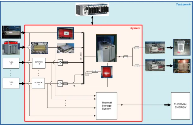
The system has been realized in the laboratory of the Departement of Industrial (DIN) and, to date consists of a 5 kWel Polymeral Exchange Membrane (PEM) FC from 5 kWel, as micro‐CHP energy source, powered by hydrogen taken directly from cylinders, from a 100 Ah lead‐acid battery storage system and a 500 W photovlotaic (PV) module emulator, all connected to a 230 V AC bus through the inverters with specific characteristic.Also electric active and reactive loads are present, feed by the common AC bus. The developed integrate energy system (IES) is able to operate both in stand‐ alone operating conditions, in which the energy system feeds the load and in grid connected operating conditions, in which the energy system is connected with the national distribution network. The passage from one to the other above operating conditions is allowed by the battery bidirectional inverter. The key features of the IES are essentially the flexibility and the dynamicity. In fact the system must be able to operate to vary the number and type of the micro‐CHP sources, the available type of fuel and any renewable energy source. Furthermore, regardless of the number and type of components, the IES must be able to meet the variable heat demand of the electricity and heat from the users.
One of the major problems affecting the development of this technology is the lifetime that to date is still excessively short.
The research conducted and exposed in this PhD thesis has addressed this problem by making an innovative contribution that consists in the development of external indices by which is possible monitor not only the electric and CHP performance but also the degradation of the PEMFC during the useful life
In fact, particular attention has been focused on the PEMFC, present into the IES, performance with a black box, component of the IES, without analyzing the individual sub‐component (single elementary cells, bipolar plates, electrodes, gas diffusion layers, membrane, etc.) and not with post‐mortem inspection of its individual components, as generally done until now.
xi
Specifically, in this Ph.D. thesis:
‐ Chapter 1 provides a description of the FC technology, with a brief summary of the technology history and of the different typological FC. In this chapter are alos described the principle of operation, the characteristics and the thermodynamics that govern the FC system, focusing in particular on PEM fuell cell type.
‐ Chapter 2 describes in detail the developed Integrated Energy System (IES), all its individual components and the principles of operation.
‐ Chapter 3 shows the experimental test campaigns carried out on the IES in order to analyze the electric and thermal performance at variable load of the PEMFC in study.
‐ Chapter 4 present a brief description of the main degradation mechanisms that affected the PEMFC tecnology, as reported in the literature.
‐ Chapter 5 describes the experimental analysis performed on the PEMFC degradation mechanisms. In particular, the investigations of the flooding at the anode side of the stack and the anodic exhaust management optimization developed have been here illustred. Furthermore, the fuel utilization factor analysis and the developed algorithm for calculating the amount of the hydrogen
(H2) reacted, not‐reacted and expelled through the dead‐end valve and of the H2
not‐ reacted due to crossover phenomenon are shown.
‐ Chapter 6 describes the analysis carried out on the aging of the PEMFC, whereas 50 h of not‐continuous operation, which led to show that the main cause
of the to PEMFC performance degradation at low loads is due to the H2 crossover
mechanism.
xii
Chapter 1
1.
THE FUEL CELL TECNOLOGY
Fuel cells (FCs) are defined as electrochemical device that directly convert chemical energy stored in fuels such as hydrogen to electrical energy.
Unlike internal combustion engines, the fuel is not combusted, but the energy is released electrocatalytically. This allows to FCs to be a low emission energy sources and also to own highly energy efficient, especially if the heat produced by the reaction is also harnessed for space heating, hot water or to drive refrigeration cycles. In fact the FCs efficiency can reach as high as 60% in electrical energy conversion and overall 80% in co‐generation of electrical and thermal energies with reduction in main pollutants greater than 90% [1].
1.1 THE HISTORY OF THE FC TECHNOLOGY [112]
Although the FC is considered a modern technology, its invention dates back more than two centuries ago. But it was only after the Second World War that the technology began to be seen as promising technological solution and its development was promoted.
In the 1830s, a Welsh judge and physical scientist, Sir William Grove (1811‐1896) conducted a series of experiments on water electrolysis. His device (Figure 1.1) consisted of two platinum electrodes dipped into water acidified with sulfuric acid. After disconnecting the current, the electrodes, at which hydrogen and oxygen had been evolved earlier as gases, were polarized, that is, a certain potential difference was preserved between them. When in this state they were linked by an external circuit, a current was found to flow in this circuit. Grove called his invention a “voltaic battery”. His results were published in 1839 in the Philosophical Magazine. This date is historically regarded as the beginning of fuel cells, although Grove himself did not regard his battery as a practical means for producing electrical energy. Figure 1.1: W. Grove (18111896) and the “Grove’s cell” present in the letter “On the Gas Voltaic Battery”.
In 1889, Ludwig Mond and Carl Langer conducted relatively successful experiments concerning the generation of electric currents using hydrogen‐oxygen cells. They researched fuel cells using coal gas as a fuel. For the first time, the “fuel cell” term was used. Further attempts to convert coal directly into electricity were made in the early twentieth century but the technology generally remained obscure.
In 1894 the German physical chemist Friedrich Wilhelm Ostwald (1853‐1932, Nobel Prize 1909) overcame the limitation of heat engines by eliminating the interim stage of fuel combustion (the formation of thermal energy), using single‐ step conversion of the fuel’s chemical energy into electrical energy. He proposed to build devices for the direct oxidation of natural fuels with the oxygen of the air, using the electrochemical mechanism occurring in ordinary batteries (“cold combustion” of natural fuels). A device to perform this direct conversion was named “fuel cell”. Figure 1.2: Friedrich Wilhelm Ostwald (18531932), Nobel Prize 1909.
In the 1920 the cell research is promoted in Germany leading the way in the development cycle and carbonate cells "solid oxide fuel cells (SOFC)" today. Meanwhile is discovered and understood the process of the combustion chamber and the oil begins to spread.
In 1932, Cambridge engineering professor Francis Thomas Bacon (1904 – 1992) developed the first AFC but it was not until 1959 that Bacon demonstrated a practical 5 kW fuel cell system. At around the same time, Harry Karl Ihrig fitted a modified 15 kW Bacon cell to an Allis‐Chalmers agricultural tractor. Allis‐ Chalmers, in partnership with the US Air Force, subsequently developed a number of fuel cell powered vehicles including a forklift truck, a golf cart and a submersible vessel. Figure 1.3: Francis Thomas Bacon (1904 – 1992) and his AFC. Then, only in the late 1950s and early 1960s NASA, in collaboration with industrial partners, began developing fuel cell generators for manned space missions. The first PEMFC unit was one of the results of those partnerships this, with Willard
Thomas Grubb at General Electric (GE) credited with the invention. Another GE
researcher, Leonard Niedrach, refined Grubb's PEMFC by using platinum as a catalyst on the membranes. The Grubb‐Niedrach fuel cell was further developed in cooperation with NASA, and was used in the Gemini space program of the mid‐ 1960s.
Contextually, International Fuel Cells (IFC, later UTC Power) developed a 1.5 kW AFC for use in the Apollo space missions. The fuel cell provided electrical power as well as drinking water for the astronauts for the duration of their mission. IFC subsequently developed a 12 kW AFC, used to provide onboard power on all space shuttle flights. While research was continuing on fuel cells in the West, in the Soviet Union fuel cells were being developed for military applications, although much of this early work is still secret. On the other hand, General Motors (GE) had experimented with its hydrogen fuel cell powered Electrovan fitted with a Union Carbide fuel cell. Although the project was limited to demonstrations, it marked one of the earliest road‐going fuel cell electric vehicles (FCEV). From the mid‐ 1960s, Shell was involved with developing DMFC, where the use of liquid fuel was considered to be a great advantage for vehicle applications. In the 1970s the emergence of air pollution promoted clean air legislation in the United States and Europe. This mandated the reduction of harmful vehicle exhaust gases. At the same time, the OPEC oil embargo there was. This led governments, businesses and consumers to embrace the concept of energy efficiency. Clean air and energy efficiency were to become two of the principal drivers for fuel cell adoption in subsequent decades, in addition to the more recent concerns about climate change and energy security. Moreover, concerns over oil availability led to the development of a number of one‐off demonstration fuel cell vehicles, including models powered by hydrogen or ammonia, as well as of hydrogen‐fuelled internal combustion engines. Many German, Japanese and US vehicle manufacturers began to experiment with FCEV, increasing the power density of PEMFC stacks and developing hydrogen fuel storage systems. The, the focus shifted back to pure hydrogen fuel, which generates zero harmful emissions. Concerns over energy shortages and higher oil prices, also prompted the PAFC technology. There were significant field demonstrations of large stationary PAFC units for prime, off‐grid power, including a 1 MW unit developed by IFC.
Furthermore, funding from the US military and electrical utilities enabled developments in MCFC technology, such as the internal reforming of natural gas to hydrogen. The use of an established natural gas infrastructure was a key advantage in developing fuel cells for large stationary prime power applications.
Also in the 1980s, technical and commercial development continued in particular for the PAFCs. Several experimental large stationary PAFC plants were built, but saw little commercial traction. With subsequent advancements in membrane durability and system performance, PAFC were rolled out in greater numbers almost two decades later for large‐scale combined heat and power applications. US Navy commissioned studies for the use of fuel cells in submarines where highly efficient, zero‐emission, near‐silent running offered considerable operational advantages.
In 1983 the Canadian company Ballard began research into fuel cells, and was to become a major player in the manufacture of stacks and systems for stationary and transport applications in later years.
In the 1990s the attention turned to PEMFC and SOFC technology particularly, for small stationary applications. These were seen as offering a more imminent commercial possibility, due to the lower cost per unit and greater number of potential markets ‐ for example backup power for telecoms sites and residential micro‐CHP. In Germany, Japan and the UK began to be significant government funding devoted to developing PEMFC and SOFC technology for residential micro‐ CHP applications.
Government policies to promote clean transport also helped drive the development of PEMFC for automotive applications. The California Air Resources Board (CARB) introduced the Zero Emission Vehicle (ZEV) Mandate. This was the first vehicle emissions standard in the world predicated not on improvements to the internal combustion engine (ICE) but on the use of alternative power trains. Carmakers such as the‐DaimlerChrysler, General Motors, and Toyota, all of which had substantial sales in the US, responded to this by investing in PEMFC research. Companies other than automakers, such as Ballard, continued PEMFC research for automotive and stationary clean power. Ballard went on to supply PEMFC units to Daimler and Ford. The programmers initiated in the 1990s still continue, albeit with some changes to the strategic focus of some key players.
Significant advances in DMFC technology occurred around the same time, as PEMFC technology was adapted for direct methanol portable devices. Early applications included portable soldier‐borne power and power for devices such as laptops and mobile phones.
MCFC technology, first developed in the 1950s, made substantial commercial advances, in particular for large stationary applications in which it was sold by companies such as Fuel Cell Energy and MTU.
SOFC technology also underwent substantial developments in terms of power density and durability for stationary applications. Boosted by general optimism in high‐technology industries, many fuel cell companies listed on stock exchanges in the late 1990s, only for prices to fall victim to the crash in technology stocks shortly after.
The 2000s were characterized by increasing concerns on the part of governments, business and consumers over energy security, energy efficiency, and carbon
dioxide (CO2) emissions. Attention has turned once again to fuel cells as one of
several potential technologies capable of delivering energy efficiency and CO2
savings while reducing dependence on fossil fuels.
Government and private funding for fuel cell research has increased markedly in the last decade. There has been a renewed focus on fundamental research to achieve breakthroughs in cost reduction and operational performance to make fuel cells competitive with conventional technology. A good deal of government funding worldwide has also been targeted at fuel cell demonstration and deployment projects. The European Union, Canada, Japan, South Korea, and the United States are all engaged in high‐profile demonstration projects, primarily of stationary and transport fuel cells and their associated fuelling infrastructure. The genuine benefits that fuel cell technology offers over conventional technologies has played a part in promoting adoption. Several fuel cell buses were deployed in the mid‐2000s as part of the HyFleet/CUTE project in Europe, China and Australia. Buses were, and still are, seen as a promising early market application of fuel cells due to their combination of high efficiency, zero‐emissions and ease of refueling, and due to the vehicles running on set routes and being regularly refueled with hydrogen at their bases.
In the 2007, fuel cells began to become commercial in a variety of applications, when they started to be sold to end‐users with written warranties and service capability, and met the codes and standards of the markets in which they were sold. As such, a number of market segments became demand driven, rather than being characterized by oversupply and overcapacity. In particular, thousands of PEMFC and DMFC auxiliary power units (APU) were commercialized in leisure applications, such as boats and campervans, with similarly large numbers of micro fuel cell units being sold in the portable sector in toys and educational kits. Demand from the military also saw hundreds of DMFC and PEMFC portable power units put into service for infantry soldiers, where they provided power to communications and surveillance equipment and reduced the burden on the dismounted solider of carrying heavy battery packs.
A large‐scale residential CHP program in Japan helped stimulate commercial stationary PEMFC shipments. These units began to be installed in homes from 2009 Demonstration programs for backup power systems in the USA gave further impetus to the stationary sector. This was also driven by practical concerns over the need for reliable backup power for telecoms networks during emergencies and rescue operations. The inadequacy of diesel generators was illustrated during the Gulf of Mexico Hurricane Katrina disaster, when many ran out of fuel, disrupting the telecoms network and hampering relief efforts. The need for reliable on‐grid or off‐grid stationary power in developing countries also gave a boost to fuel cells. Hydrogen and natural gas fuelled PEMFC units began to be sold in parts of India and east Africa to provide primary or backup power to mobile phone masts. The rapidity of mobile phone adoption in these regions means that the conventional grid infrastructure cannot keep pace with new power demands, or is too unreliable for an effective mobile network. Fuel cells provide a solution to this previously unmet need.
In transport applications, the greatest commercial activity occurred in the materials handling segment, where there is a strong business case for their use in place of the incumbent technology, lead acid batteries. Funding for demonstration fleets of fuel cell materials handling vehicles saw increasing numbers deployed in warehouses across the USA, although the overall numbers remained small
compared with those for stationary and portable fuel cells. Fuel cell buses have been commercially available for several years and their usefulness has been well demonstrated. However their cost, at around five times that of a diesel bus, plus the cost of hydrogen infrastructure means that they are only used where a city deems the environmental benefit to be worth the extra investment. Fuel cell cars are currently only available for lease; these vehicles are being made available by manufacturers to gain experience ahead of a commercial launch planned from 2015.
In the past decade, PEMFC and DMFC have dominated the total market share in the portable, stationary and transport sectors. Their uptake by consumers has been facilitated by the development of codes, standards and government policies to lower the barriers to adoption; such as allowing methanol fuel cartridges on board of aircraft and feed‐in tariffs for fuel cell CHP installations.
Over the last five years growth in shipments of fuel cells has accelerated rapidly as various applications have become commercial. Portable fuel cells saw the most rapid rate of growth over the period since 2009 as increasing numbers of fuel cell educational kits were sold to consumers. This genuine commercial market generated much‐needed revenue for several key players and has allowed those companies to invest in research into larger stationary and transport applications. The portable sector has also been boosted by shipments of APU products for the leisure market, in particular camping and boating. Shipments in the portable sector were also augmented by the launch of Toshiba's Dynario fuel cell battery charger in 2009. On a limited production run of 3,000, demand for the Dynario far outstripped supply. Stationary fuel cell adoption has increased rapidly as the roll‐ out of the Japanese Ene‐Farm project took place and fuel cells for uninterruptible power supplies (UPS) were adopted in North America.
The supply chain has also been steadily growing alongside the increase in the number of fuel cell system manufacturers. There has been an expansion of the component supply chain and related services, from the manufacturers of MEA to fuel and infrastructure providers. Manufacturing capacity has tended to increase more rapidly than output. This is particularly true in North America, one of the leading regions for fuel cell manufacturing.
The global economic recession of the late 2000s undoubtedly had negative effects for certain fuel cell companies. Limited credit availability and restrictions in government funding, as well as lack of profitability for organizations that were still mainly R&D focused, caused a number of firms to go out of business.
The fuel cell industry has faced and continues to face challenges as it comes through a period of recession and completes the transition from R&D to commercialization. On the whole, it has survived extremely difficult circumstances. Although many fuel cell companies are still far from being profitable, the opportunities for growth in the future are very promising. The success of certain application segments in recent years means that there has been a move to consolidate particular technologies into a standard reference design for a particular type of fuel cell. This has led to fuel cells increasingly being developed as scalable energy solutions capable of serving several different market segments, be they APU or to power devices such as unmanned aerial vehicles (UAV).
1.2 DESCRIPTION OF THE FC TECHNOLOGY
As it defined by its inventor Grove, a fuel cell (FC) is a “galvanic cell”, e.g. a device that generates electrical energy by converting the energy of chemical reactions. Other varieties of electrochemical power sources are the throw‐away batteries for domestic use and storage batteries, used for example in automobiles, personal computers, cell phones.
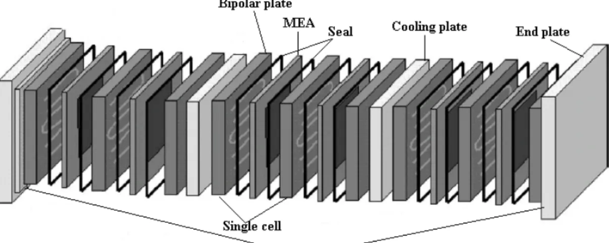
On the contrary of these batteries, in which the chemical reactions are used to create electricity, and the reacting materials, as well as the reaction products, are typically metals or other solid compounds (oxides, salts, etc.) In fuel cells both the reactants and the products are typically liquids or gases. This permits the continuous supply of reactants to the cells and a continuous removal of the reaction products. Thus, fuel cells can be used for power generation without interruption, as long as the reactants are continuously supplied and the reaction products are removed, without the need to be recharged and/or discharged. The FC consists of two porous electrodes separated by an electrolyte which carry out the electrochemical conversion of the energy contained in the fuel introduced to one of the two electrodes. Although FCs are classified according to the type of electrolyte, because it changes in a decisive way the kinetics and the type of chemical reactions, they present anyway similar thermodynamic principles and gas diffusion mechanisms to the electrodes. In particular, a FC unit consists of a stack, which is composed of a number of individual cells.
Each cell (Figure 1.4) within the stack has two electrodes, one positive called the cathode, and one negative, called the anode. The reactions that produce electricity take place at the electrodes. Every fuel cell also has either a solid or a liquid electrolyte, which carries ions from one electrode to the other, and a catalyst, which accelerates the reactions at the electrodes. The electrolyte plays a key role ‐ it must permit only the appropriate ions to pass between the electrodes. If free electrons or other substances travel through the electrolyte, they disrupt the chemical reaction and lower the efficiency of the cell.
Figure 1.4: Single cell scheme. Precisely, the reacting gases, hydrogen and oxygen (typically is air), are supplied to the individual electrodes. The overall reaction is split into two partial reactions. On anode, hydrogen molecules are oxidized, that is, they transfer their electrons to the metallic electrode with the formation of positive hydrogen ions (protons). At the other electrode, the cathode, oxygen molecules are reduced, that is, electrons are transferred to them from the metallic electrode. These two partial reactions taken together yield the same product as the overall reaction. Thus, in the electrochemical reaction scheme, the overall reaction occurs as two partial reactions spatially separated at two different electrodes immersed into the electrolyte solution. During this reaction, the anode acquires electrons and becomes negatively charged, while the cathode loses electrons and becomes positively charged. To avoid accidental contacts between anode and cathode (producing an internal short of the cell) and to avoid the intermixing of the fuel and oxygen, an insulating porous separator is often placed in the gap between the two electrodes.
When the two electrodes are connected outside the cell through some electrical device, the electrons flow from the anode (the negative pole of the cell) to the cathode (positive pole). Within the cell, the hydrogen ions formed at the anode are
transferred to the cathode where they participate in the electrode reaction. The moving ions in the solution and electrons in the metal together yield a closed electrical circuit. When the circuit is closed through the external device, the partial reactions proceed and the external electric current is maintained continuously, as long as the reacting gases are supplied to the electrodes. Thus, some of the chemical energy of the overall reaction is converted to electrical energy used in the external device. The remaining part of the chemical energy is lost for practical purposes and it is dissipated as heat, because extra energy is needed to force the reaction to proceed at a finite rate (overvoltage). However, this loss can be considerable less than the loss occurring in the conventional thermal‐mechanical‐ electrical energy conversion systems.
1.3 FC
STIPOLOGY
Fuel cell types are generally classified according to the nature of the electrolyte they use. Although each type requires particular materials, fuels, operation temperature and is suitable for different applications. The main FC typologies are seven: − PEM (Proton Exchange Membrane FC) − AFC (Alkaline FC) − DMFC (Direct Methanol FC) − PAFC (Phosphoric Acid FC) − MCFC (Molten Carbonate FC) − SOFC (Solid Oxide FC)
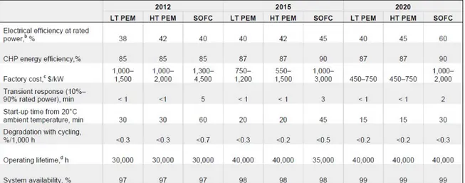
The first four types (AFC, PEMFC, and DMFC) are called low temperature FCs, while the last two (PAFC, MCFC and SOFC) are known as middle and high‐ temperature FCs. The characteristics for each type are summarized in Table 1.1.
PEMFC PAFC MCFC SOFC
Temperature[°C] 60÷110 190÷200 600÷700 650÷900 Pressure [atm] 1÷3 1÷8 1÷8 1÷14 Size (Pel) [kW] 1÷250 100÷1000 250÷10000 1÷10000 Efficiency [%] 30÷40% 38÷45% 45÷55% 45÷60% Power density [mW/cm2] ̴700 ̴200 ̴160 200(circular) 500(planar)
Fuel H2 H2 H2/CH4/CO H2/CH4/CO Oxidant O2/Air O2/Air O2/Air/CO2 O2/Air Impurity
Tolerance
CO<10 ppm CO< 1%
H2S,COS<50ppm
H2S,COS<1 ppm H2S < 1 ppm
Reforming Ext. or int. External Ext. or int. Ext. or int.
Cogenerazione Water @ 70‐80°C Water/steam Steam Steam
1.3.1 THE AFC (ALKALINE FC)
Figure: 1.5: The AFC scheme.
AFCs use an alkaline electrolyte such as potassium hydroxide in water and are generally fuelled with pure hydrogen. The first AFCs operated at between 100 °C and 250 °C but typical operating temperatures are now around 70 °C. As a result of the low operating temperature, it is not necessary to employ a platinum catalyst in the system and instead, a variety of non‐precious metals can be used as catalysts to speed up the reactions occurring at the anode and cathode. Nickel is the most commonly used catalyst in AFC units. The reactions that occur to the electrodes are: cathode anode electrolyte oxigen hydrogen
Anode: H2 +2(OH)‐ Î 2H2O + 2e‐ (1.1)
Cathode: ½O2 + 2H+ + 2e‐ Î 2(OH)‐ (1.2)
The oxygen reduction reaction and hydrogen oxidation taking place within the alkaline medium involving hydroxyl ions. The hydroxyl ion formed by the cathodic reduction of the water migrates through the electrolyte, to the anode, where, recombining with hydrogen, just oxidized to produce water.
Due to the rate at which the chemical reactions take place these cells offer relatively high fuel to electricity conversion efficiencies, as high as 60% in some applications [13].
One of the major problems of an AFC is the formation of carbonates., through the oxidation of the carbon support present on the electrode "gas diffusion" (in open circuit condition), it clogs the pores rapidly decreasing the performance of the cell, By the recirculation of the solution of KOH, however, avoids the formation of carbonates. Furthermore, the carbon dioxide can be removed from the hydrogen and the air stream through a system "iron‐sponge", which is similar to the shift
reaction which takes place in a reformer, or via the CO2 absorption swing. This type of fuel cell was the first to be developed, but due to their sensitivity to the presence of carbon dioxide have been progressively abandoned in favor of other types of cell. Remain very promising if you have pure hydrogen.
1.3.2 THE DMFC (DIRECT METHANOL FC)
Figure 1.6: The DMFC scheme.
DMFC uses a polymer membrane as an electrolyte. However, the platinum‐ ruthenium catalyst on the DMFC anode is able to draw the hydrogen from liquid methanol, eliminating the need for a fuel reformer. Therefore pure methanol can be used as fuel, hence the name. The reactions at the electrodes are: Methanol offers several advantages as a fuel. It is inexpensive but has a relatively high energy density and can be easily transported and stored. It can be supplied to the fuel cell unit from a liquid reservoir which can be kept topped up, or in cartridges which can be quickly changed out when spent.
Anode: CH3OH + H2O Î CO2 + 6H+ + 6e‐ (1.4)
Cathode: 3/2O2 + 6H+ + 6e‐ Î 3H2O (1.5)
DMFCs operate in the temperature range from 60 °C to 130 °C and tend to be used in applications with modest power requirements, such as mobile electronic devices or chargers and portable power packs. One particular application for DMFC power units for commercial materials handling vehicles. A number of these units have been sold to commercial warehouses, where the forklift trucks had been conventionally powered with battery packs. By switching to fuel cells, the warehouses can refuel their trucks in a matter of minutes, compared to the hours it would take to charge a battery. The fuel cells also eliminate the need for a battery charging infrastructure within the warehouse, thereby making more floor space available for other uses.
1.3.3 THE PAFC (PHOSPHORIC ACID FUEL CELLS)
Figure 1.7: The PAFC scheme.
PAFCs consist of an anode and a cathode made of a finely dispersed platinum catalyst on carbon and a silicon carbide structure that holds the phosphoric acid electrolyte. The reactions at the electrodes are: They are quite resistant to poisoning by carbon monoxide but tend to have lower efficiency than other fuel cell types in producing electricity. However, these cells operate at moderately high temperatures of around 180ºC and overall efficiency can be over 80% if its process heat is harnessed for cogeneration.
Anode: H2 Î 2H+ + 2e‐ (1.7)
Cathode: ½O2 + 2H+ + 2e‐ ÎH2O (1.8)
This type of fuel cell is used in stationary power generators, with output in the 100 kW to 400 kW range, to power many commercial premises around the world, and they are also finding application in large vehicles such as buses. Most fuel cell units sold before 2001 used PAFC technology. 1.3.4 THE MCFC (MOLTEN CARBONATE FC) Figure 1.8: The MCFC scheme.
Molten carbonate fuel cells (MCFCs) use a molten carbonate salt suspended in a porous ceramic matrix as the electrolyte. Salts commonly used include lithium carbonate, potassium carbonate and sodium carbonate.
The reactions at the electrodes are: ‐ Using hydrogen as fuel: ‐ Using carbone monoxide as fuel: They operate at high temperature, around 650 °C and there are several advantages associated with this. Firstly, the high operating temperature dramatically improves reaction kinetics and thus it is not necessary to boost these with a noble metal catalyst. The higher temperature also makes the cell less prone to carbon monoxide poisoning than lower temperature systems. As a result, MCFC systems can operate on a variety of different fuels, including coal‐derived fuel gas, methane or natural gas, eliminating the need for external reformers.
Disadvantages associated with MCFC units arise from using a liquid electrolyte rather than a solid one and the requirement to inject carbon dioxide at the cathode as carbonate ions are consumed in reactions occurring at the anode. There have also been some issues with high temperature corrosion and the corrosive nature of the electrolyte but these can now be controlled to achieve a practical lifetime.
Anode: H2 + ½O2 Î H2O (1.10)
Cathode: H2 + CO32‐ Î H2O + CO2 + 2e‐ (1.11)
(overall reaction) ½O2 + CO2 + 2e‐ Î CO32‐ (1.12)
Anode: CO + ½O2 Î CO2 (1.13)
Cathode: CO + CO32‐ Î 2CO2 + 2e‐ (1.14)
MCFCs are used in large stationary power generation. Most fuel cell power plants of megawatt capacity use MCFCs, as do large combined heat and power (CHP) and combined cooling and power (CCP) plants. These fuel cells can work at up to 60% efficiency for fuel to electricity conversion, and overall efficiencies can be over 80% in CHP or CCP applications where the process heat is also utilized.
1.3.5 THE SOFC (SOLID OXIDE FC)
Figure 1.9: The SOFC scheme.
SOFCs use a solid ceramic electrolyte, such as zirconium oxide stabilized with yttrium oxide, instead of a liquid or membrane. Their high operating temperature means that fuels can be reformed within the fuel cell itself, eliminating the need for external reforming and allowing the units to be used with a variety of hydrocarbon fuels. They are also relatively resistant to small quantities of sulphur in the fuel, compared to other types of fuel cell, and can hence be used with coal gas.
This FC typology work at very high temperatures, the highest of all the fuel cell types at around 800 °C to 1,000 °C. They can have efficiencies of over 60% when converting fuel to electricity; if the heat they produced is also harnessed; their overall efficiency in converting fuel to energy can be over 80%.
The reactions at the electrodes are:
A further advantage of the high operating temperature is that the reaction kinetics are improved, removing the need for a metal catalyst. There are however some disadvantages to the high temperature: these cells take longer to start up and reach operating temperature, they must be constructed of robust, heat‐resistant materials, and they must be shielded to prevent heat loss.
There are three different SOFC geometries: planar, coplanar and micro‐tubular. In the planar design, components are assembled in flat stacks where the air and hydrogen traditionally flow though the unit via channels built in to the anode and cathode. In the tubular design, air is supplied to the inside of an extended solid oxide tube (which is sealed at one end) while fuel flows round the outside of the tube. The tube itself forms the cathode and the cell components are constructed in layers around the tube.
SOFCs are used extensively in large and small stationary power generation: planar types find application in, for example, Bloom Energy's 100 kW off‐grid power generators and SOFCs with output of a few kilowatts are being tested for smaller cogeneration applications, such as domestic combined heat and power (CHP). Micro‐tubular SOFCs with output in the watt range are also being developed for small portable chargers.
Anode:
H2 + O2‐ Î H2O + 2e‐
CO + O2‐ ÎCO2 + 2e‐
CH4 + 4 O2‐ Î 2H2O + CO2 + 8e‐
(1.16) (1.17) (1.18)
Cathode: ½O2 + 2e‐ Î O2‐ (1.19)

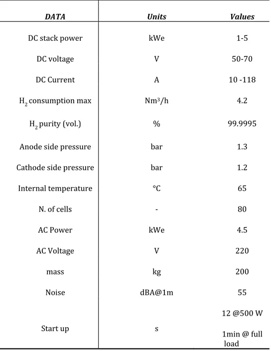
![Figure 1.19: The breakdown of fuel cell cost [1].](https://thumb-eu.123doks.com/thumbv2/123dokorg/8171126.126935/81.892.154.741.635.989/figure-the-breakdown-of-fuel-cell-cost.webp)