UNIVERSITÀ DI PISA
Dipartimento di Fisica
The experience in a
Center of Excellence in Preclinical Imaging:
from the set-up of
the PET/SPECT laboratory
to the routine experimental activity
Medical Physics thesis
of
Antonietta Bartoli
Advisor:
Co-advisor:
Prof. Enzo Terreno
Prof. Alberto Del Guerra
Contents
1 Introduction 1
2 The role of preclincal imaging 5
2.1 The importance of small animal models in molecular imaging . . . 7
2.2 Molecular imaging instrumentation and techniques . . . 9
2.2.1 Radionuclide imaging . . . 13
2.2.2 Optical imaging . . . 14
2.2.3 Magnetic resonance imaging . . . 18
2.2.4 X-ray computed tomography . . . 20
2.2.5 Ultrasound . . . 21
2.3 General requirements for molecular imaging . . . 22
2.4 Specific applications of PET molecular imaging . . . 24
2.4.1 Glucose metabolism in brain and heart . . . 24
2.4.2 Dopaminergic system in rat brain . . . 25
2.4.3 Oncology . . . 25
2.4.4 Reporter gene expression imaging . . . 26
3 Radioprotection issues in PET/SPECT imaging 29 3.1 Basic principles in radioprotection . . . 30
3.2 Law provisions . . . 31
3.2.1 Dosimetric quantities . . . 31
3.2.2 Dose limits and areas and workers classification . . . 33
3.3 Hazards of employed sources . . . 34
3.4 Physics principles to minimize external radiation exposure . . . 36
3.6 Shielding requirements . . . 40
4 The set-up of the PET/SPECT laboratory 47 4.1 The Center of Excellence in Preclinical Imaging (CEIP) . . . 48
4.2 Employed sources . . . 50
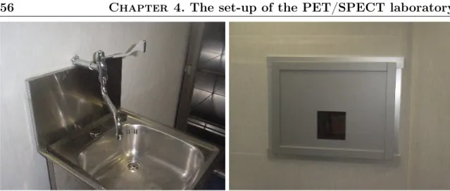
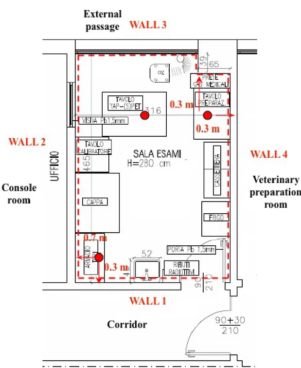
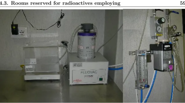
4.3 Rooms reserved for radioactives employing . . . 51
4.3.1 PET/SPECT laboratory shielding . . . 56
4.4 Evaluation of the dose to exposed personnel and to the public . . . . 62
4.4.1 Dose evaluation to exposed personnel: external irradiation . . 63
4.4.2 Dose evaluation to exposed personnel: internal irradiation . . 68
4.4.3 Dose evaluation for CEIP workers not assigned to PET/SPECT laboratory . . . 71
4.4.4 Dose evaluation for the public . . . 71
4.4.5 Evaluation in case of accident . . . 71
4.5 Production and management of radioactive wastes . . . 72
4.6 Classification of the areas and of the workers . . . 73
5 The YAP-(S)PET scanner 77 5.1 The YAP-(S)PET scanner overview . . . 77
5.2 The main hardware components . . . 78
5.2.1 Scintillator crystals: YAP:Ce . . . 78
5.2.2 Position Sensitive Photomultiplier Tube (PSPMT) . . . 83
5.2.3 Electronic read-out . . . 84
5.2.4 SPECT collimator . . . 86
5.3 The software tools . . . 89
5.3.1 Client/server architecture . . . 89
5.3.2 Acquisition . . . 90
5.3.3 Analysis . . . 92
5.3.4 Reconstruction . . . 97
5.3.5 Display . . . 104
6 Small animal imaging studies 107 6.1 Response to chemotherapy in prostate tumor-bearing mice . . . 108
CONTENTS iii
6.1.1 Materials and methods . . . 110
6.1.2 Results . . . 115
6.1.3 Discussion . . . 118
6.1.4 Conclusion . . . 120
6.2 Monitoring anti-rheumatic therapies in an arthritis mouse model . . . 121
6.2.1 Materials and Methods . . . 123
6.2.2 Results . . . 125
6.2.3 Conclusions . . . 126
6.3 PET/MRI multimodality study . . . 127
6.3.1 Imaging systems and compatible bed development . . . 129
6.3.2 Phantom tests: Image quality . . . 130
6.3.3 In vivo imaging . . . 131 6.3.4 Co-registration . . . 132 6.3.5 Results . . . 132 6.3.6 Discussion . . . 134 7 Conclusion 139 Bibliography i
Chapter 1
Introduction
Molecular imaging can be defined as the visual representation, characterization and quantification of biological processes at the cellular and subcellular levels within in-tact living organisms [1]. Generally speaking, molecular imaging involves specialized instrumentation, used alone or in combination with targeted imaging agents, to vi-sualize tissue characteristics and/or biochemical markers [2]. The field of molecular imaging is highly multidisciplinary, drawing from many areas of science, including, but not limited to, molecular biology, biochemistry, physiology, physics, engineering, genetics, mathematics, chemistry, pharmacology, immunology, and medicine. Molec-ular imaging of living subjects can trace its roots back to nuclear medicine, never-theless many techniques are now possible. In fact, techniques using optical signaling, as well as signaling using magnetic resonance imaging (MRI), ultrasound (US), Ra-man, photoacoustics (PA), and computed tomography (CT), have also been steadily increasing. And although still in its infancy, molecular imaging is showing enormous promise in the areas of diagnostics, therapy monitoring, drug discovery and devel-opment, and understanding nanoscale reactions such as protein-protein interactions and enzymatic conversion.
Biomedical research utilizing small animals such as mice and rats has expanded dramatically in the past few years as molecular biology and imaging techniques open new opportunities to investigate models of disease (see chapter 2). The growing number of mouse and rat experiments, coupled with the increasing number of dedi-cated small animal imaging systems such as microPET, optical, microCT, microMRI,
ultrasound and microSPECT, has led to the development of common technical cen-ters for imaging small animals. Increasingly sophisticated molecular probes and tool sets allow researchers to examine multiple processes at once in the same animal by using different light wavelengths (optical), various molecular imaging probes (PET and SPECT) and different contrast agents (MRI and CT), as well as to define the anatomical structures in which these processes take place. This, in turn, has led to a demand for comprehensive, multimodality imaging facilities that can house animals, support imaging systems, and provide investigators with the tools, methods, and other infrastructure necessary for successful imaging experiments [3].
The creation of the Center of Excellence in Preclinical Imaging (CEIP) is part of this expansions. The CEIP is an Academic/Industry partnership and offers to universities, research centers and companies know-how and methodologies based on imaging techniques in order to easy and speed up the process of development of new diagnostic and therapeutics solutions. In fact, it is equipped with several state of the art imaging devices: 3 small MRI system, a PET/SPECT and a PET/SPECT/CT scanners, an Ultra sound and Optical system (see chapter 4).
This thesis deals with the experience in the Center of Excellence in Preclinical Imaging, CEIP: from the set-up of the PET/SPECT laboratory to the routine ex-perimental activity.
Chapter 2 presents an overview of the main characteristics of molecular imaging, explaining why small animal imaging is necessary and describing the features of the main molecular imaging systems and their applications in the field.
Chapter 3 describes the basic concepts in radioprotection, mainly focusing of the practical considerations for safe radioisotopes and animal handlings in a PET/SPECT laboratory.
In chapter 4, after a brief introduction of the Center of Excellence in Preclinical Imaging (CEIP), the layout of the PET/SPECT laboratory is reported together with the evaluation of the radiation exposure to both personnel and public, the manage-ment of the radioactive wastes and residuals and the classification of the areas and of the workers.
3 YAP-(S)PET scanner. The YAP-(S)PET User Friendly interface and the reconstruc-tion algorithms are widely reported.
Finally, chapter 6 describes a few case animal studies performed within the CEIP, the Center of Excellence in Preclinical Imaging Both longitudinal PET and SPECT studies are reported, besides a PET/MRI multimodality realized with an hand-made support that allow to perform the two acquisitions without animal repositioning.
Chapter 2
The role of preclincal imaging
When Watson and Crick elucidated the double-helical structure of DNA in 1958, they made the greatest discovery of the XX century in the biological sciences. This discovery initiated a time in biology in which biological and physical scientists would strive to unravel the genetic code and its regulated expression, which determines the genotypic basis for the phenotypes of all the cells within the organism. Today, intense exploration is taking place in the biological sciences to determine the patterns of gene expression that encode for normal biological processes, such as replication, migration, signal transduction of cell communication, and the many other functions that cells perform. In addition, belief is growing that most diseases result from altered patterns of gene expression that transition cells to the phenotypes of disease. These alterations in gene expression can result from interactions with the environment, hereditary defects, developmental errors, and aging. As a result, biology is coming together with medicine to design ways to identify these fundamental molecular errors of disease and develop molecular corrections for them. The general name given to this emerging field is molecular medicine [4].
As biology and medicine come together, it is important that imaging also merges with biology to form the technologies referred to as biological or molecular imaging. Many scientists state that molecular imaging is not a new discipline: nuclear imaging approaches such as positron emission tomography (PET) and single-photon emission computed tomography (SPECT) have been using molecular imaging con-cepts for more than a decade to visualize the biodistribution of labeled compounds
including analyses of receptor occupancy. In these studies image contrast is not gov-erned by the anatomical features of the sample but rather by the local concentration of the radio-labeled reporter compound, i.e., by a molecular property.
Other scientists claim that molecular imaging is a new scientific area merging concepts of molecular biology with noninvasive imaging technologies. This allows the study of biological processes in a noninvasive manner. These concepts go beyond labeling of reporter ligands. They involve the development of a great number of reporter assays that are used to probe specific biological questions. Is the expression of a receptor modified under specific pathological conditions? Does the receptor exert its biological activity? Does it activate its associated signaling cascade? Can these molecular markers be used as early indicators of a pathological transformation? [5]
A precise definition of molecular imaging is an elusive and perhaps not particularly important goal [6]. Rather the term reflects a shift in emphasis and a shift in atti-tude, moving from the undeniably useful, but largely non-specific, diagnostic imaging approaches that are currently employed in the clinic, to targeting specific genes and proteins that are known to be linked directly or indirectly to human disease.
The emergence of molecular imaging strategies is largely due to recent unprece-dented advances in molecular and cell biology techniques, the use of transgenic animal models, availability of newer imaging drugs and probes that are highly specific, and successful development of small-animal imaging instrumentation [1]. This creates the possibility of achieving several important goals in biomedical research:
• to develop noninvasive in vivo imaging methods that reflect specific cellular and molecular processes, for example, gene expression, or more complex molecular interactions such as protein-protein interactions.
• to monitor multiple molecular events near-simultaneously. • to follow trafficking and targeting of cells.
• to optimize drug and gene therapy.
• to image drug effects at a molecular and cellular level.
2.1. The importance of small animal models in molecular imaging 7 • to create the possibility of achieving all of the above goals of imaging in a rapid, reproducible and quantitative manner, so as to be able to monitor time-dependent experimental, developmental, environmental, and therapeutic influ-ences on gene products in the same animal or patient.
2.1
The importance of small animal models in
molec-ular imaging
Molecular imaging in living subjects offers distinct advantages when compared with conventional in vitro and cell culture research techniques in biology.
In contrast to cell and tissue culture, in vivo animal models allow the assessment of phenomena such as tolerances, complementation, and redundancy in biological pathways. Molecular imaging permits both the temporal and the spatial biodistribu-tion of a molecular probe and related biological processes to be determined in a more meaningful manner throughout an intact living subject [1].
Imaging technologies are playing a growing role in animal research, enabling large, expensive laboratory animals to be studied noninvasively and providing the possibil-ity of reducing the number of small laboratory animals required in typical longitudinal studies. As each animal serves as its own individual control, the reproducibility of data from imaging studies may actually be better than that obtained from tradi-tional invasive techniques, although this improvement has yet to be demonstrated unequivocally. Finally, imaging provides a bridge from animal research to human research.
Since the mid 1980s, the effort to understand mammalian biology and the study of disease models have caused the mouse to become the animal of choice. More than 90% of all mammals used worldwide in research in the year 2000 were mice [7]. The rapid rate of reproducibility and short life span of mice aid in keeping down the cost of maintaining colonies and favor them as a molecular biology research vehicle. In addition, most human genes have a related mouse gene, allowing mice to be used as a platform for mimicking many human disease [8]. Furthermore, modern molecular biology contains the technology to “knock-out” or disable genes, and to insert or
“knock-in” new ones in order to create many types of transgenic mice. The mouse genome has been the second mammalian genome to be sequenced after the human genome [9].
Molecular imaging of living mice offers distinct advantages when investigating phenotypic abnormalities [1]:
• it eliminates the need to kill such mice as part of their phenotype determination. • by repetitive imaging it is possible to investigate mutants that are otherwise
difficult to interpret with data taken at a single time point.
• it allows concomitant visual and analytical biological phenotyping of animals. • it allows the researcher to exercise options of multiple imaging strategies (e.g.,
by using different imaging reporter probes or modalities) in cases in which simple genetic manipulations could result in a very complex phenotype involving a large number of pathways and organs.
Moreover, in vivo mouse imaging as an alternative to killing many animals for histological processing at different time points is also convenient in terms of money. With each transgenic mouse valued in the 200-300 dollars range, the overall costs of conventional post mortem biological assays on many animals can mount substantially. The use of fewer animals in biological assays with molecular imaging would also be more appealing on ethical grounds. In theory, approval for research projects requiring large numbers or many separate cohorts of experimental animals could be obtained more easily [1].
Molecular imaging assays in intact living animals could be of further benefit in resolving biological questions raised by pharmaceutical scientists. Transgenic animals are useful in guiding early drug discovery validating the target protein, evaluating test compounds, determining whether the target is involved in any toxicological effects of test compounds, and testing the efficacy of compounds to ensure that the compounds will act as expected in man [1].
In some disciplines, particularly in neuroscience, the rat also remains an important experimental animal, partly due to the ease of surgical manipulation of the rat brain
2.2. Molecular imaging instrumentation and techniques 9 versus the mouse brain (2 g as opposed to 0.45 g). In addition, there is a large historical knowledge base of both the anatomy and the function of the rat brain, deriving from many decades during which it was the preferred model [10].
2.2
Molecular imaging instrumentation and techniques
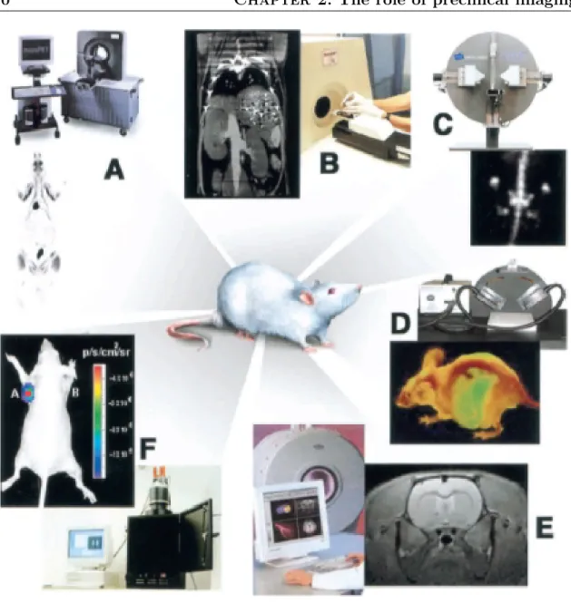
Biological discovery has moved at an accelerated pace in recent years, with consider-able focus on the transition from in vitro to in vivo models. As such, there has been a greater need to adapt clinical imaging methods for noninvasive assays of biochemical processes. Considerable efforts have been directed in recent years toward the develop-ment of noninvasive, high-resolution, small animal in vivo imaging technologies (see figure 2.1). The widespread availability and use of miniaturized imaging systems for rodents are invaluable resources for basic science laboratories. Nonetheless, signifi-cant challenges remain to be overcome when attempting to image a 30-g mouse as compared with a 70-kg human, including the size of the subject, the total volume that must be evaluated, the spatial resolution necessary for obtaining meaningful anatomical and/or functional data, and the total time spent on acquiring a set of images [11]. A comparison between human and small animal size can be obtained by figure 2.2.
In small animal research, the primary goal is to obtain as high a signal as possible and to localize the signal as accurately as possible with high temporal resolution and with minimal amount of molecular probe. The ultimate goal is to provide a device that produces a three-dimensional image of anatomical and biological information fused together. The various existing imaging technologies differ for the following main aspects [1]:
• spatial and temporal resolution. • depth penetration.
• energy used for image generation (ionizing or nonionizing, depending on which component of the electromagnetic radiation spectrum is exploited for image generation).
Figure 2.1: Illustrative examples of the variety of images that can be obtained with different imaging modalities. (A) microPET whole-body coronal image of a rat injected with18FDG, showing uptake of tracer in tissues including muscles, heart, brain, and accumulation in bladder owing to renal clearance. (B) microCT coronal image of a mouse abdomen after injection of intravenous iodinated contrast medium. (C) microSPECT coronal image of a mouse abdomen and pelvis regions after injection of 99mTc methylene diphosphonate, showing spine, pelvis, tail vertebrae, femurs, and knee joints owing to accumulation of tracer in bone. (D) Optical reflectance fluorescence image of a mouse showing GFP fluorescence from the liver, abdomen, spine, and brain. The mouse contains GFP-expressing tumor cells that have spread to various sites. Images are courtesy of Dr. Hoffman, Anticancer Inc. (E) microMRI coronal T2-weighted image of a mouse brain. (F) Optical bioluminescence image of a mouse with a subcutaneous xenograft expressing Renilla luciferase in the left shoulder region, after tail-vein injection of the substrate coelenterazine. Images were obtained using a cooled CCD camera. The color image of visible light is superimposed on a photographic image of the mouse with a scale in photons per second per square centimeter per steradian (sr) [1].
2.2. Molecular imaging instrumentation and techniques 11
Figure 2.2: Relative size of a human, rat and mouse brain [12].
• availability of injectable/biocompatible molecular probes.
• the respective detection threshold of probes for a given technology.
Table 2.1 outlines some of the general characteristics of the imaging modalities available.
Imaging Spatial T emp oral Sensitivit y Molecular Amoun t Quan titativ e A dv an tages Disadv an tages Cost tec hnique resolution resolution (mol/l) prob e of prob e degree PET 1-2 mm 10 s to min 10 − 11 − 10 − 12 nanograms +++ high sensitivit y; ++++ isotop e can radiolab elled substitute PET cyclotron direct or indirect naturally o ccurring or generator atoms; translational needed quan titativ e studies SPECT 1-2 mm min utes 10 − 10 − 10 − 11 nanograms ++ man y molecular +++ radiolab elled prob es a v ailable; lo w direct or indirect m ultiple prob es sensitivit y sim ultaneou sl y Optical bio-3-5 mm seconds not w ell c harac-activ able micrograms + to ++ high sensitivit y lo w spatial ++ luminescence to terized, p ossibly indirect to quic k, easy resolution; imaging min utes 10 − 15 − 10 − 17 milligrams lo w cost 2D only Optical 2-3 mm seconds 10 − 9 − 10 − 12 activ able micrograms + to ++ high sensitivit y lo w spatial +/++ fluorescence to direct resolution imaging min utes or indirect MRI 25-100 µ m min utes not activ able micrograms + to ++ high spatial lo w sen si tivit y; ++ to w ell direct to resolution long time hours c h ar a cter ized or indirect milligrams Ultrasound 50-500 µ m seconds not limited activ able micrograms + to ++ real time; mostly + to w ell direct to lo w cost morphological min utes c h ar a cter ized or indirect milligrams T able 2.1: Characteristi cs of imaging mo da lities a v ailable in molecular imag ign. T emp oral resolution refe rs to the frequency at whic h the final in terpretable v ersion of images can b e recorded/c aptured from the sub ject once the imaging pro cess is initiated. This re lates to the time required to collect enou gh ev en ts to form an image, and to the resp onsi v eness of the imaging system to rates of an y change induced b y the op erator or in the biological system at hand [1].
2.2. Molecular imaging instrumentation and techniques 13
2.2.1
Radionuclide imaging
The primary advantage of radioactive assays (whether in vivo, ex vivo or in vitro) is their exquisite sensitivity and the ability, with appropriate care, of radiation de-tection systems to provide quantitative measurements of radioactivity concentrations deep inside tissue. Radiolabelled tracers have a long history of being used to elu-cidate physiology, metabolic pathways and molecular targets [13], and to provide a high sensitivity tool for molecular imaging studies. A very large number of radio-labelled tracers have been developed to probe specific biological targets and func-tions [14], and a growing number are moving into clinical use. An important strength is the availability of radionuclides of biologically relevant elements, particularly car-bon, allowing contrast agents to be labelled by direct isotopic substitution. This allows small biomolecules (many drugs, receptor ligands, etc.) to be labelled without changing their biochemical properties. Another powerful approach is to create analog radiotracers, in which deliberate chemical changes are made to a biologically active molecule to isolate specific pathways or cause specific trapping of a radiotracer in cells expressing the target of choice. Analog radiotracers are also designed to allow the use of isotopes of elements that are not found within the molecule of interest, but that have good imaging properties. Larger biomolecules (peptides, antibodies, RNA, synthetic macromolecules) are also readily labelled with a wide range of radionuclides that have excellent properties for imaging. A list of the major radionuclides that are currently being used for in vivo nuclear imaging is provided in table 2.2. A further advantage is that nuclear imaging approaches are readily translated to the clinic, as the majority of the listed radionuclides produce photons with sufficient tissue pen-etration for studies in man. Disadvantages of nuclear imaging approaches include obvious factors such as the involvement of ionizing radiation, and more subtle factors such as the fact that radioactive decay cannot be controlled, hence there is always non-specific background signal present in an image due to non-specific binding of radiotracers, residual radiotracer in the circulation and routes of excretion [6].
Nuclear imaging techniques include high resolution (<100 µm) ex vivo autoradio-graphic techniques using film, phosphor storage plates or real time autoradioautoradio-graphic systems [15] and in vivo methods using radionuclides that produce appropriate energy
photons (gamma-rays, annihilation photons or characteristic x-rays with energies in the range of 25-511 keV) during decay. The in vivo methods are further broken up into: single photon imaging that utilize radionuclides with single or multiple uncorre-lated gamma ray emissions and PET in which radionuclides decay by positron emis-sion resulting in two simultaneous annihilation photons emitted back-to-back [16].
The development of higher resolution and higher sensitivity animal PET and SPECT systems is allowing molecular and genomic imaging approaches, tradition-ally approached by ex vivo autoradiographic methods, to be translated in vivo into animal models of disease [17,18]. Dramatic improvements in image quality have been achieved by using novel detector and collimation approaches, and by exploiting the more favourable environment found in small animal imaging.
One of the advantages of nuclear imaging, say as, compared to optical imaging, is that the radiation involved is highly penetrating, and so the dependence of the detected signal on the depth at which it is emitted is fairly small. Even without cor-rection for scatter and attenuation, nuclear images within small animals can exhibit fairly high quantitative accuracy in specific circumstances and with the appropriate calibration object [6].
Radionuclide Half life Energy of principle Imaging modality
photons (keV) 11C 20.4 mins 511 PET 18F 110 mins 511 PET 64Cu 12.7 h 511 PET 99mTc 6.02 h 140 SPECT 111In 2.83 days 171, 245 SPECT 123I 13.2 h 159 SPECT 124I 4.18 days 511, 603, 723, 1690 PET 125I 60.1 days 27, 31, 35 SPECT 131I 8.04 days 354 SPECT
Table 2.2: Radionuclides commonly used for in vivo nuclear imaging.
2.2.2
Optical imaging
There has been tremendous growth in the use of optical approaches for in vivo imag-ing of small laboratory animals. This is in part due to the accessibility of optical
2.2. Molecular imaging instrumentation and techniques 15 approaches, and also in part because of their extremely high sensitivity. Light is both scattered and absorbed in tissues, but there is an absorption minimum cor-responding to wavelengths in the approximate range of 700-950 nm [19]. At these wavelengths, the light is still readily scattered but the absorption length is on the order of several centimetres. Thus, light emitted from deep inside a small animal has a reasonable probability of reaching the surface for external detection. Although this light has in general scattered many times when it reaches the surface, some posi-tional information is retained based on the intensity, spatial distribution and spectral distribution of the emitted light [20]. This region of the electromagnetic spectrum is known as the “optical window” because of the more favourable characteristics for imaging through tissue.
At the present time, most studies are based on imaging the intensity of the emitted light at the surface of the animal with straightforward detector systems that are amenable for use in biology labs and have the capability of relatively high throughput. Two distinct contrast mechanisms are being used for molecular and genomic imaging studies: one involving fluorescence [21], and the other involving bioluminescence [22]. In fluorescence imaging, an external light source, either a laser, or a broadband source (e.g., a mercury lamp) with an appropriate low-pass filter, is used to excite fluorescent molecules inside the subject. These fluorescent molecules may be geneti-cally engineered into a mouse, for example by incorporating the gene for a fluorescent protein as a reporter gene. Green Fluorescent Protein (GFP) has been widely used in this manner for cell culture and tissue slice experiments, but is less well suited for in vivo use because of the relatively short excitation (peak ∼ 470-490 nm) and emis-sion (peak ∼ 510 nm) wavelengths that place it outside the optical window and in a part of the spectrum where there is significant autofluorescence of tissue components. Despite these difficulties, GFP has been used successfully for some in vivo imaging studies [23]. Subsequently, GFP mutants and other fluorescent proteins have been discovered that have excitation and emission spectra better suited to in vivo imag-ing [24–26]. Another approach to introducimag-ing fluorescent molecules into an animal is to use fluorophores (or more recently, fluorescent particles known as quantum dots) as labels on biologically interesting molecules [27]. This is analogous to radionuclide
labelling for nuclear imaging, although the approach generally is limited to the la-belling of larger biomolecules where the size of the fluorophore does not interfere with the biological activity of the agent. Again, fluorophores that are excited and emit in or close to the optical window are preferred for good penetration depth and large amplitude signals [6]. Table 2.3 provides data on a number of fluorophores that are being used for in vivo studies and an example of a study carried out with a near infrared fluorescence probe is shown in figure 2.3.
Name Type of agent Excitation Emission Extinction coefficient Quantum max (nm) max (nm) (cm−1 M−1) yield Cy 5 Fluorophore 649 670 250000 0.28 Cy 5.5 Fluorophore 675 694 190000 0.23 Cy 7 Fluorophore 743 767 200000 0.29 Alexa Fluor 700 Fluorophore 702 723 192000
Alexa Fluor 750 Fluorophore 749 775 240000
EGFP Fluorescent protein 489 508 55000 0.60 DsRed Fluorescent protein 558 583 57000 0.79 mRFP1 Fluorescent protein 584 607 44000 0.25
Table 2.3: Properties of some fluorophoresa and fluorescent proteins. (Data for DsRed and
mRFP1 from [26]. Other data from manufacturers’ datasheets [6].)
There are two key advantages to fluorescence imaging. Firstly, many of the flu-orophores used have high quantum yields, leading to robust signals when using ap-propriate illumination and acquisition times. Secondly, as described earlier, the flu-orescence emission can be activated by specific biologic molecules or events. This eliminates signal from contrast agent that is circulating and from paths of excretion (a limiting problem for radiotracers), reducing background “noise”. This allows very low concentrations (subnanomolar, and with some activatable agents, picomolar or better) of enzymes to be detected. The disadvantage of fluorescence imaging is that there is autofluorescence from tissue that forms a background that ultimately limits detection sensitivity. A second problem is that light has to get into the animal (to excite the fluorescent molecules) and back out again (to reach the detector). Because of the high degree of scattering of both the excitation and emission light, it is not possible to excite and isolate the fluorescence within very small volumes of tissue inside the animal. As a consequence of the strong dependence on depth of both the
2.2. Molecular imaging instrumentation and techniques 17 intensity of the excitation light and the detection of the emission light, quantitative analysis of the images, in all but the very simplest cases of a small point emitter, becomes extremely difficult [6].
Fluorescence imaging can be carried out using conventional CCD cameras. The use of back-illuminated CCDs and cooling, enhances sensitivity and signal-to-noise ratio, but for many studies general purpose scientific CCD cameras are sufficient, because detection sensitivity is limited by autofluorescence rather than by the noise characteristics of the detector. A simple black box and a lens coupled CCD camera connected to a computer can yield acceptable fluorescence images showing the light distribution on the surface of the animal in just a few seconds or minutes [28].
The second approach to in vivo optical imaging involves introducing reporter genes that encode for enzymes (known as luciferases) that can catalyze a light-producing reaction. This process is called bioluminescence and luciferases are found in organisms such as fireflies, glow worms and jellyfish [29]. The most commonly used reporter gene for imaging is the one that encodes for firefly luciferase [30]. This gene is introduced as a reporter gene. Just prior to imaging, animals are injected with the substrate for the enzyme. In the case of the firefly luciferase the substrate is luciferin, a small molecule that rapidly distributes throughout the whole body of the mouse after intravenous or intraperitoneal injection. In cells that are expressing the luciferase reporter gene, the luciferin, in the presence of oxygen and ATP (Adenosintriphospat), is converted to oxyluciferin with the emission of light (peak at 560 nm). The reaction is catalyzed by the luciferase enzyme and does not occur to any significant extent when luciferase is absent. The generation of an optical signal is therefore specific to cells that contain the reporter gene. Mutations of the naturally occurring firefly gene has resulted in a shifting of the emission peak to around 620 nm, with significant amounts of light being emitted in the 550-700 nm range, improving its sensitivity for in vivo imaging studies [22].
The advantage of the bioluminescence approach is that there is no need for ex-ternal light stimulation. There is no problem, therefore, in depth of penetration of the excitation light as there is with fluorescence, and there is no autofluorescence background to contend with. The disadvantage is that this approach is limited to
studying genetically manipulated cells or transgenic mice, or infectious agents such as bacteria and viruses, as the reporter gene has to be introduced to the organism that is to be studied. Also, the bioluminescence signals are typically very weak. These low signals require the use of high quantum efficiency CCDs that are cooled to minimize dark current over the integration time required to obtain an image (typically a few minutes) [6].
The biggest efforts in optical imaging at the present time are devoted to moving from a single image of the light intensity projected at the surface of the animal to tomographic images that provide information on the distribution of the light source in 3D. This involves acquiring data from a small number of views such that the light intensity across the surface of the entire mouse can be mapped.
Figure 2.3: In vivo bioluminescence images (in colour) from cancer cells carrying a luciferase
reporter gene. These images show the growth of a pituitary tumour over a period of four weeks. The greyscale image is a reflectance light image of the mouse for anatomic reference [6].
2.2.3
Magnetic resonance imaging
Magnetic Resonance Imaging (MRI) is one of the more mature technologies for small animal imaging. Magnetic resonance microscopy (generally defined as imaging with a resolution of better ∼ 100 microns) has been around since the mid 1980s and has found particular applications in neuroscience [31, 32] and developmental biology [33]. High-field magnets are introduced in small-bore animal imaging systems several years before they can be achieved for larger bore human applications. Therefore these ani-mal systems serve as important test-beds and catalysts for developing high resolution,
2.2. Molecular imaging instrumentation and techniques 19 high speed and high sensitivity pulse sequences. Most small-animal imaging is cur-rently carried out on horizontal-bore instruments with field strengths between 4.7 T and 9.4 T and bore sizes of 20-40 cm. Research systems with field strengths as high as 11.7 T (40 cm horizontal bore) and 21.1 T (8.9 cm vertical bore) are also being evaluated for small-animal imaging [34]. Higher field strengths are desirable for high-resolution imaging because the signal-to-noise ratio (SNR) is proportional to field strength, and the detected signal is proportional to the tissue volume within a voxel. A reduction in voxel size from 1 × 1 × 1 mm to 0.1 × 0.1 × 0.1 mm therefore results in a 1000-fold reduction in the detected signal.
Since SNR is only linearly proportional to field strength, higher fields only in part make up for the reduced voxel size in high resolution images. Therefore, images at resolutions of tens of microns can only be achieved with very long acquisition times, typically many hours for a whole mouse.
In vivo images of anatomy with a spatial resolution of a few hundred microns can be achieved in several minutes with MRI when combined with appropriate physiologic gating to control cardiac and respiratory motion. Sophisticated physiologic monitor-ing and forced respiration systems have been developed to allow motion-free in vivo imaging and well controlled physiologic status deep inside a high-field magnet [35]. The good soft-tissue contrast achieved by well-designed pulse sequences has led to MRI becoming the method of choice for following anatomic changes in soft tissue that may be related to a disease course or an intervention. Furthermore, MRI has the ability to measure physiological parameters, including water diffusion and blood oxygenation levels (which leads to the contrast used in functional MRI to study brain activation). The addition of “passive” contrast agents, such as Gd-DTPA, further en-hances the utility of MRI, allowing vascular density, permeability and perfusion to be
assessed. Another example of a passive agent is the use of Mn2+ ions for tract-tracing
studies in the brain [36].
Taken together, these MRI methods provide a powerful set of tools for interro-gating anatomic and physiologic changes that are a consequence of specific cellular or molecular alterations in living animals. Of more interest is the development of targeted and activatable contrast agents for MRI that offer the prospect of direct
molecular imaging. These agents are based on transition metals or lanthanides that are paramagnetic and change the relaxation time (either T1 or T2) in tissue regions in which they accumulate [37].
One area of active research is into optimal RF coil design for high-field use. Design of better volume coils should improve SNR and allow imaging of an entire animal in significantly shorter times. High-powered imaging gradients with fast switching rates for small-volume imaging have also improved the ability to acquire fast images at higher signal-to-noise, and further improvements in the gradient coils are also likely [6].
2.2.4
X-ray computed tomography
In vivo imaging of small animals with CT has a critical role to play in the evolution of molecular imaging [38, 39]. The conventional anatomic CT with non-specific con-trast agents is a relatively straightforward way to obtain high-resolution anatomic information which is often important to analyze molecular imaging studies obtained using other modalities (especially nuclear and optical approaches). MicroCT is also a valuable tool for indirect approaches to molecular imaging [38], for example, imag-ing changes in vascular density and permeability associated with angiogenesis and anti-angiogenic therapeutics. MicroCT is the method of choice for tracking changes in diseases that affect bone. The high resolution of microCT allows very sensitive de-tection of bone growth, destruction, remodelling and changes in bone density, and is therefore ideally suited for studying the consequences of diseases such as osteoporosis and rheumatoid arthritis, and for evaluating the effects of therapeutic interventions on the progression of these diseases [6]. MicroCT also has the potential to be used as a fairly high-throughput imaging technique and investigators are considering its use for phenotypic screening in genetically manipulated mice [40].
Some of the specific and continuing challenges in moving from specimen imaging to in vivo imaging have been to reduce the radiation dose, deal with motion artefacts, change the system geometry to allow the animal to be placed horizontally and remain stationary during scanning and to decrease imaging time.
2.2. Molecular imaging instrumentation and techniques 21 specimen imaging or digital mammography, and systems generally acquire data in
cone-beam geometries. This imaging geometry is relatively simple to implement
and the 3D collection makes the most efficient use of the relatively modest x-ray flux that is emitted by the compact microfocus fixed anode x-ray tubes generally employed in these applications [41]. These low-power tubes are supported by compact power supplies and the small x-ray focal spot size offers the potential for very high spatial resolution. At the same time, the anode current (and hence number of x-rays produced) of these compact tubes is limited by the small focal spot size and the fixed anode design when operated continuously for CT acquisition. Typical x-ray tube parameters used in microCT systems are focal spot sizes in the range of 10-100 microns, and tube currents of at most a few mA at an anode voltage of 25-75 kV. Most commonly, tungsten anode tubes are being utilized. For CT imaging, the x-ray tube is generally operated continuously with a shutter to control when x-rays irradiate the object. A resolution of tens of microns is achievable in some microCT systems [6].
2.2.5
Ultrasound
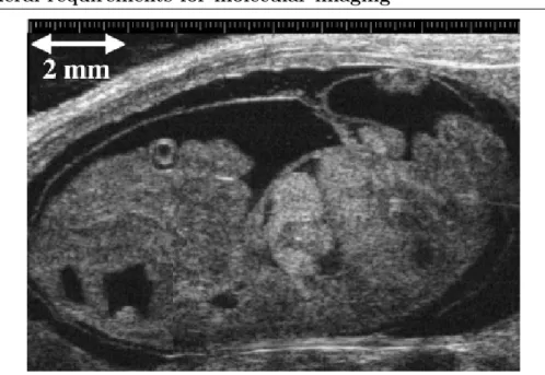
Ultrasound also has been successfully adapted as a tool for small animal imaging and together with the development of novel echogenic contrast agents promises to add molecular imaging capability in a number of very important areas. Advantages of ultrasound include real-time imaging, portability, low cost, high spatial resolution and the absence of ionizing radiation. One of the key trade-offs in ultrasound is between acoustic frequency, depth of penetration, and spatial resolution. In small-animal models, a depth of penetration of 1-2 cm is generally sufficient, allowing high frequencies on the order of 20-60 MHz to be used. This leads to a spatial resolution in the range of tens of microns [6]. One of the really unique capabilities of ultra-sound is in developmental studies [42], particularly pre-natal studies in genetically manipulated mice (see figure 2.4). Genetic manipulations often result in embryonic lethal phenotypes that do not survive to birth, hence the ability to determine phe-notypes in utero is extremely important. High-resolution embryonic imaging cannot be performed noninvasively with any other modality at the present time due to fetal motion, which requires very fast acquisition. The real-time nature of ultrasound is
also of importance in studying cardiac anatomy and function in rodents, and opens up opportunities for image-guided interventions in animal models.
The capabilities of ultrasound go far beyond anatomic imaging for phenotypic analysis. High frequency Doppler flow mapping enables quantitative measurements of blood flow not only in major vessels, but importantly, also in the microcirculation [43]. Contrast agents are being developed that promise to give ultrasound a major role in molecular imaging and therapeutics [44, 45]. In their simplest form, these contrast agents are small bubbles (typically 1-10 microns in diameter) in which a lipid or albu-min shell is filled with a gas such as perfluoropropane. These microbubbles produce very strong ultrasound echoes due to differences in their compressibility and den-sity compared to surrounding biologic tissues. In fact a standard clinical ultrasound system can detect the echo from an individual microbubble, thus in principle, the sensitivity for detection of such contrast agents is extremely high. Microbubbles are already in clinical use, where they are used to detect small vessels and capillary beds by enhancing the signal from the small volume of blood. In addition, microbubbles have interesting non-linear oscillation properties in response to ultrasound radiation. With appropriate acoustic pressure, these bubbles can actually burst. By applying local acoustic pressure to burst the bubbles, the contrast agent can be selectively destroyed within a small volume of tissue. By imaging the return of the signal as blood containing intact contrast agent flows into the region, it is possible to quantify important physiologic parameters such as blood velocity, blood flow and blood vol-ume in the microvasculature. These measurements can be repeated over and over for a single contrast agent injection with high spatial and temporal resolution [6].
2.3
General requirements for molecular imaging
The acquisition of ex vivo information in biomedical research has become relatively easy, because a myriad of specialty reagents, ligands, protocols, and devices have been commercially developed over the past two decades. On the other hand, molecular imaging in living subjects presents more theoretical and practical challenges than in vitro or cell culture detection, primarily because of the need for probes to be
2.3. General requirements for molecular imaging 23
Figure 2.4: High frequency (40 MHz) ultrasound image of a 13.5-day-old mouse embryo.
The resolution in this image is better than 100 microns. (Adapted with permission of World Federation of Ultrasound in Medicine and Biology from [46]).
biocompatible, the presence of additional delivery barriers, and the necessity for developing special in vivo amplification strategies [47]. There are several general areas in which considerable research efforts are ongoing [11,28] and will also be necessary in the future to perform in vivo molecular imaging (by seeking answers to the questions in parenthesis) [1]:
• selection of appropriate cellular and subcellular targets to image (what biolog-ical process is to be imaged?).
• development of suitable in vivo affinity ligands, that is, molecular imaging probes (what biocompatible chemical/biochemical/ molecular entity can be used in vivo to distinguish that particular biological process and help to gener-ate specific images of that target?).
• delivery of these probes in a manner that efficiently overcomes biological bar-riers (what are the pharmacokinetic attributes of these probes contributing to successful imaging?).
• amplification strategies able to detect minimal target concentrations, usually in the pico-to nanomolar range (can the imaging signal be amplified?).
• development of imaging systems with high spatial/temporal resolution and sen-sitivity suitable for small laboratory animals, and that ultimately can be trans-lated to the human patient (what are the imaging modalities and instrumenta-tion available to achieve molecular imaging in living subjects?)
2.4
Specific applications of PET molecular imaging
The use of either of PET or SPECT in small animal biological research has the ad-vantage that essentially the same methodology can be used in human applications,
thereby facilitating translation to the clinic. The classical example of a
transla-tional research application in molecular medicine is the introduction of STI- 571
(Gleevec ), a small molecule designed to alter specific intracellular signalling path-R
ways involved in cell proliferation and apoptosis, which lead to chronic myeloid leukaemia [48]. STI-571 specifically inhibits the oncogenic protein tyrosine kinase breakpoint cluster region (BCR)Abelson (ABL), which is constitutively activated by a chromosomal translocation.
Some PET molecular imaging specific applications are reported.
2.4.1
Glucose metabolism in brain and heart
The probe of excellence in PET studies of metabolism is 2-deoxy-2-[18
F]fluoro-D-glucose (FDG). It is transported into cells by the F]fluoro-D-glucose transporter and subsequently converted to the phosphorylated form by hexokinase. FDG-6-phosphate, the product of hexokinase, cannot be further metabolized and is “trapped” inside cells, where its accumulation can be measured in the PET scanner.
In the latest generation of small animal PET systems, the spatial resolution is sufficient (<2 mm) to clearly identify structures such as the thalamus, striatum, and cortex subunits and to separate extracerebral activity from cerebral activity in the adult rat. A range of semiquantitative investigations of brain plasticity and conscious brain activation have been performed [49] and a series of fully quantitative longitu-dinal studies in a traumatic brain injury model, complete with direct comparison to quantitative 2DG autoradiography [50], have also been reported. Even at this
resolu-2.4. Specific applications of PET molecular imaging 25 tion, though, there is a problem with brain FDG studies in small rats and mice, due to spillover of activity from the Harderian glands into the cortex. The same spillover problem has been reported in adult rats as well, but with poorer resolution tomo-graphs [51]. Small animal PET scanners are also being employed to measure glucose
metabolism and myocardial blood flow (with 13N-ammonia) in rat and mouse heart
models of ischemia and infarction. Initial investigations comparing infarct extent [52] and FDG uptake [53] against in vitro measures are promising. The group at Sher-brooke University and Prof. Markus Schwaiger of the Nuklearmedizinische Klinik und Poliklinik der Technischen Universitat Munchen, Munich, Germany have also demonstrated the feasibility of acquiring gated PET images of the rat heart [54, 55].
2.4.2
Dopaminergic system in rat brain
Some of the earliest small animal PET work used a variety of probes to explore the dopaminergic system in the rat brain. Probes that reflect dopamine synthesis (e.g.,
18F-fluoro-metatyrosine,18F-FDOPA), D2 receptor binding (e.g.,11C-raclopride,18
F-fluoroethylspiperone), and dopamine transporter concentration (e.g., 11C-CFT) are
available [10]. These probes are accumulated to a high degree in the striata, which are fairly large and well separated in the rat brain. Therefore, successful investigations can be performed even at moderate 3- to 4-mm spatial resolution [56]. This work demonstrated, for example, the ability of PET to quantify D2 receptor in the living rat brain [57], the survival and function of neural transplants [58–60], and the effects of drugs on D1 and D2 receptors [61, 62]. An example from one of these studies is shown in figure 2.5.
2.4.3
Oncology
Some of the best opportunities for small animal PET imaging are in oncology. Study-ing transplanted primary tumors is often simple since they can be placed away from major organs in the thigh, shoulder, or back of the animal. Under these circum-stances, corrections for partial volume are straightforward. In addition, the usual variability between one animal and the next is effectively removed and each animal can be used as its own control. Furthermore, PET can survey the entire animal and
Figure 2.5: Coronal section through rat brains showing D1 and D2 receptor binding fol-lowing injection of11C-SCH 23390 and 11C-raclopride respectively. Four different rats are shown: control rat; lesioned rat (unilateral ibotenic acid lesion); lesioned rat following graft of striatal cells from 15-mm crown to rump fetuses; lesioned rat following graft of striatal cells from 10-mm crown to rump fetuses. Rats with grafts were scanned approximately 10 months post surgery. Note: Loss of D1 and D2 binding signal on right side of image following lesion and partial recovery of the signal in the rat that received a striatal graft [10].
allows the spread of metastatic disease to be observed and monitored [10]. There is a range of PET probes that are of interest in cancer models, including FDG,
3’-deoxy-3’- [18F]fluorothymidine (FLT), a marker of DNA replication and cell
pro-liferation [63], and labeled antibodies and antibody fragments [64]. The power of serial PET investigations as a tool for assessing the time course and localization of antibody fragments is demonstrated in Figure 2.6, which illustrates a mouse imaged using an anti- CEA minibody, a genetically engineered antibody fragment that binds with high affinity to carcinoembryonic antigen [65].
2.4.4
Reporter gene expression imaging
The merger of molecular imaging with molecular biology to create methods to mea-sure reporter gene expression in vivo with PET is an area that has attracted increasing interest. In analogy with the way Green Fluorescent Protein (GFP) is used as a stan-dard reporter gene in molecular biology [66], a PET reporter gene (PRG) expresses a
2.4. Specific applications of PET molecular imaging 27
Figure 2.6: Coronal PET image of a mouse injected with a radiolabeled anti-CEA minibody,
a genetically engineered antibody fragment that binds with high affinity to carcinoembryonic (CEA) antigen. The minibody was radiolabeled with the positron emitter 124I and used for microPET imaging of LS174T tumor xenograftbearing mice. The mouse shown had a 73-mg tumor on the left shoulder, and was injected with 60 Ci of 124I anti-CEA 18 h before imaging. Note the absence of anatomical landmarks besides the faint mouse outline. The engineered antibody fragment (minibody) is also illustrated [10].
protein that can trap or bind a positron-labeled probe [67–72]. These are called the PET reporter probes. The reporter gene is driven by the same promoter as the gene of interest (the promoter can be thought of as a “switch” that turns the expression of the gene on or off), such that the gene of interest is always expressed along with the reporter gene. The retention of the positron-labeled probe by the protein product of the PRG has been shown to be proportional to the level of reporter gene expression. In turn, this reflects the level of expression of the gene of interest, which has the same promoter or is coupled directly to the PRG (i.e., PRG coupled to a therapy
gene) [73]. In this way, the location, magnitude of expression, and time course of expression levels of any gene that is introduced into a mouse can be monitored in vivo. This allows gene therapy protocols to be monitored in vivo, both in animal models and, ultimately, in humans by PET. The same PRG approach can be used in transgenic mice, where every cell in the mouse carries the PRG. In this case, the signal is only detected when the promoter driving the PRG is switched on in the nat-ural location where specific genes are expressed. This now enables endogenous gene expression to be investigated in mice models [74]. Figure 2.7 is an image of a mouse bearing two tumors, each expressing a separate reporter gene, namely the HSV1-tk gene and the dopamine type 2 receptor (D2R) gene. The mouse was injected in two
different instances with two different reporter probes, 3-(2’-[18F]fluoroethyl)-
spiper-one (FESP) and 8-[18F]fluoropenciclovir (FPCV), each probe being specific for one
of the gene reporter systems. The image shows clearly the selectivity of the reporter probes in each tumor [75].
Figure 2.7: Image of a mouse bearing two tumors, each tumor expressing a different reporter
gene. The one on the right carries the HSV1-tk reporter gene and the one on the left, the D2R reporter gene. The mouse was injected with two different reporter probes, FESP and FPCV, on two separate days. Each probe was specific for one of the gene reporter systems. The image shows clearly the selectivity of the reporter probes in each tumor. Background activity is seen from routes of clearance of tracer, which are renal and gastrointestinal [10].
Chapter 3
Radioprotection issues in
PET/SPECT imaging
Radiation is naturally present in our environment and has been since the birth of this planet. It comes from outer space (cosmic), the ground (terrestrial), and even from within our own bodies. It is present in the air we breathe, the food we eat, the water we drink, and in the construction materials used to build our homes. Certain foods such as bananas and brazil nuts naturally contain higher levels of radiation than other foods. Brick and stone homes have higher natural radiation levels than homes made of other building materials such as wood. Consequently, life has evolved in an environment which has significant levels of ionizing radiation [76].
However, it has been recognized since early studies on X rays and radioactive minerals that exposure to high levels of radiation can damage the tissues of the human body. In addition, long term epidemiological studies of populations exposed to radiation, especially the survivors of the atomic bombing of Hiroshima and Nagasaki in Japan in 1945, have demonstrated that exposure to radiation also has a potential for the delayed induction of malignancies. It is therefore essential that activities involving radiation exposure, such as the production and use of radiation sources and radioactive materials, and the operation of nuclear installations, including the management of radioactive waste, be subject to certain standards of safety in order to protect those individuals exposed to radiation [77].
use of radioactive isotopes that create ionizing radiation, with half lives ranging from minutes to days.
3.1
Basic principles in radioprotection
Radiation exposure limits or standards were introduced as early as the start of the 20th century when the potential hazards of radiation were realized. One of the first standard-setting bodies was the International Commission on Radiological Protection (ICRP), which continues its function through its series of publications. These reports form the basis for many national protection guidelines [78]. It is exactly in the ICRP Publication #60 [79], that ICRP defines a system of dose limitation based on three principles:
• Justification of the practice: no practice shall be adopted unless its intro-duction produces positive net benefit.
• Optimization of the protection: all exposure shall be kept as low as rea-sonably achievable considering the economic and social factors. This principle is known also as ALARA (As Low as Reasonably achievable) principle.
• Dose limit: the dose equivalent to individuals shall not exceed the limits recommended for the appropriate circumstances by the Commission.
The term practices refers to all the human activities that add radiation exposure to that which people normally incur due to background radiation, or that increase the likelihood of their incurring exposure [77].
The three ICRP principles have been completely acknowledged by the Italian Law Decreto Legislativo 230 of the 1995 (D.Lgs. 230/95) and by the subsequent modifications and integration (s.m.i.), in particular by the Decreto Legislativo 241 del 26 Maggio 2000 (D.Lgs. 241/2000) [80] that acknowledges the European disposal EURATOM 29 of the 1996 [81].
3.2. Law provisions 31
3.2
Law provisions
According to the D.Lgs. 230/95 and s.m.i., every times a new practice employing ra-dioactive sources is introduced or extended, a specific authorization must be required. The authorization request has to be presented to authorities.
The Italian legislation foresee to get informed the following authorities: A.S.L. Dipartimento di prevenzione, Comando provinciale dei vigili del fuoco, A.R.P.A. and the Direzione Provinciale del lavoro. A radioprotection report reviewed by a Qualified Expert, in which the level of exposure, the risk for the workers and the public and the eventual shielding required are reported, must be prepared.
For the purposes of radiation protection, ionizing radiation exposures are divided into three types [82]:
• Medical exposure, which is mainly the exposure of patients as part of their diagnosis or treatment.
• Occupational exposure, which is the exposure of workers incurred in the course of their work, with some specific exclusions.
• Public exposure, which comprises all other exposures of members of the pub-lic that are susceptible to human control.
3.2.1
Dosimetric quantities
The quantities in which the dose limits are expressed are the equivalent dose (HT)
and the effective dose (E) in tissue or organ T [80]. The effective dose is generally considered to be an adequate indicator of the health detriment from radiation ex-posure at the levels experienced in normal operations. A limit on equivalent dose is needed for skin and the lens of the eye in order to ensure the avoidance of
determin-istic effects in these tissues. The protection quantities E and HT relate to the sum of
the effective or equivalent doses received from external sources within a given time and the committed effective or equivalent doses from intakes of radionuclides that
occurred within that time [82]. The equivalent dose HT ,R in the tissue or organ T
HT,R= wR· DT,R (3.1)
where:
• DT,R is the average absorbed dose in the tissue or organ T due to radiation R;
• wR is the weighting factor for the radiation R. This factor assumes the value 1
for X-rays, γ and electrons, 5 for protons, a value in the range 5-20 for neutrons according to their energy and 20 for α particles or heavy ions.
The effective dose E (see equation 3.2) is defined as the sum of the weighted equivalent doses in the body tissues and organs due to both internal and external radiation: E =X T wR· HT = X T wT X R wT · DT ,R (3.2) where:
• HT is the equivalent dose in the tissue or organ T;
• wT is the weighting factor for the the tissue or organ T;
• wR is the weighting factor for the radiation R.
• DT,R is the average absorbed dose in the tissue or organ T due to radiation R.
Both HT and E have the same unit of measurement of the absorbed dose, namely
joule per kilogram, but the name sievert (Sv) is used in order to avoid confusion with the unit of absorbed dose (Gy).
The total effective dose ET received or committed during any time period t can
be estimated from the equation 3.3:
E = ET + X j h(g)j,ingJj,ing+ X j h(g)j,inaJj,ina (3.3) where:
3.2. Law provisions 33 • hj,ing and hj,ina are the dose coefficients for, respectively, ingestion and
inhala-tion of radionuclide j by age group g;
• Jj,ing and Jj,ina are the intakes, via ingestion and inhalation respectively, of
radionuclide j during time period t.
3.2.2
Dose limits and areas and workers classification
A dose limit is defined as “The value of the effective dose or the equivalent dose to individuals from controlled practices that shall not be exceeded. The limits on effective dose for occupational exposure apply to the sum of effective doses from external sources and committed effective doses from intakes in the same period” [77], according to the equation 3.3.
The limits on effective dose (E) for occupational exposure is fixed to 20 mSv per
year or an equivalent dose (HT) to the lens of the eye of 150 mSv in a year or an
equivalent dose to the extremities (hands and feet) or the skin of 500 mSv in a year. The equivalent dose limits for the skin apply to the average dose over any skin surface
of 1 cm2. The effective dose limit for public exposure is 1 mSv per year. To this limit
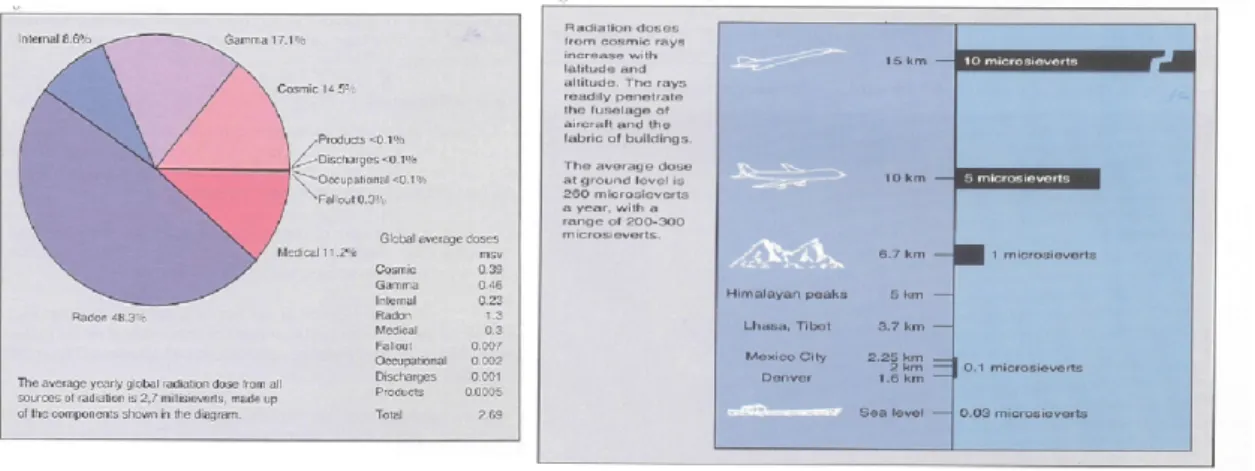
do not contributes neither the natural radiation nor the cosmic rays (see figure 3.1).
Figure 3.1: Left: average yearly global radiation dose from all sources of radiation. Right:
radiation dose from cosmic rays.
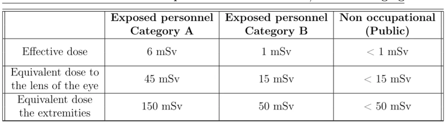
The occupational exposure classifies the personnel according to the possibility or the risk to exceed one of the limits reported in Table 3.1.
Exposed personnel Exposed personnel Non occupational
Category A Category B (Public)
Effective dose 6 mSv 1 mSv < 1 mSv
Equivalent dose to
45 mSv 15 mSv < 15 mSv
the lens of the eye Equivalent dose
150 mSv 50 mSv < 50 mSv
the extremities
Table 3.1: Radition dose limits for not exposed people (Public) and for exposed personnel.
classified. A classified area is one where there is a need to adopt procedural controls to ensure an optimized level of protection and compliance with the relevant dose limits. Two types of area may be defined: controlled and supervised areas.
In a controlled area the following requirements must be fulfilled: – the access is signaled and regulated;
– there is the risk to exceed the dose limit for Exposed personnel in Category A; – it is required the periodic environmental control performed by the Qualified
Expert and the dosimetric control of the classified personnel. In a supervised area:
– the access is signaled;
– there is the risk to exceed the dose limit for the Public.
3.3
Hazards of employed sources
As reported in section 3.2, when dealing with radiation hazards, two different expo-sition processes must be taken in account: external and internal radiation. Each of which has a different hazard degree depending on the radiation type [83]. In fact,
X-ray, γ, β, e−and neutron emissions lead to exposures depending on the nature and
energies of the corresponding radiation as well as the packaging and geometry of the source [84].
PET imaging employs β+ emitters, whose positrons undergoes annihilation with
3.3. Hazards of employed sources 35
simultaneously, in 1800 degrees opposing directions. Thus concerning radiation
pro-tection, we are dealing with gamma radiation of 511 keV energy.
SPECT imaging employs γ emitters of variable energies ranging from ∼ 30 keV
of the 125I to more than 300 keV of 125I. For radioprotection issues, it must be taken
in account, that a few SPECT tracers, like 99mTc have also a β− or electron
emis-sion. Besides, it must be considered that in PET/SPECT imaging both sealed and unsealed sources can be employed. The sealed sources are point-like, linear or planar solid sources usually employed during calibration procedures. While unsealed ones are liquid sources that can be employed for both scanner calibration and in vivo experiments.
Electron radiation can be a radiobiological hazard for both external or internal radiation. In the external radiation two processes can be distinguished: the direct or Bremsstrahlung radiation. In the direct radiation, the electrons can be easily shielded by a few millimeters thick material. In the Bremsstrahlung radiation, the shielding
used to stop the direct β−radiation can itself produces X-rays due to bremsstrahlung.
This radiation can be reduced by using shielding materials with low atomic number (Z).
X and γ radiation. The X and γ hazards are directly connected with their high penetration capabilities in both air and living tissues. About internal radiation, the high penetration power of X and γ rays is an advantage. In fact, the energy released to the tissues is distributed in a bigger volume, so the released energy per unit of mass (dose) is lower respect to charged particles like electrons. On the contrary, external radiation photons presents a high hazards since in air they can propagate far from the source without or with low attenuation (the mean free path of a 511 keV photon is about 100 m in air [85]). Shielding realized with thicker and with high Z materials are then necessary compared to electrons shieldings.
3.4
Physics principles to minimize external radiation
exposure
There are three principal methods by which external radiation protection can be minimized:
• time
The absorbed dose of an organism exposed to radiation is directly proportional to the exposition time, then reducing the time spent near a radiation will reduce one’s radiation exposure. The time reduction can be achieved by having a thorough understanding of the tasks to be performed, i.e., it is worthwhile to have practiced the steps to perform with the source with a non-radioactive substance so to learn how to better proceed.
• distance
The exposure rate from a point source of radiation (i.e., a source whose physical dimensions are much less than the distance from which it is being measured) decreases as the distance from the source squared [86].
• shielding
The decision to utilize shielding, and its type, thickness and location of a par-ticular application are functions of the photon energy, intensity and geometry of the radiation sources and exposure rate goals at various locations.
3.5
Considerations for safe radioisotopes and animal
handlings
In performing PET/SPECT imaging both external and internal radiation hazards are present. Thus, safely practices from radiotracers handling to storage aspects, and from delivery to final disposal are necessary to reduce the potential risks.
To this aim the following considerations are addressed on radiotracers handling and storage aspects, from delivery to final disposal.
3.5. Considerations for safe radioisotopes and animal handlings 37 • Personal protective equipment and clothing
To minimize the potential for personnel contamination personal protective equip-ment and clothing have to be worn, including laboratory coat, gloves and shoe covers.
• Eating and drinking
To minimize intake of radioactive material by personnel, eating or drinking, including chewing gum or smoking, should not be permitted in contamination areas [87].
• Delivery of radioactive compound
Receiving and storing areas are necessary. If the cyclotron is close to the
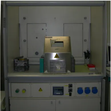
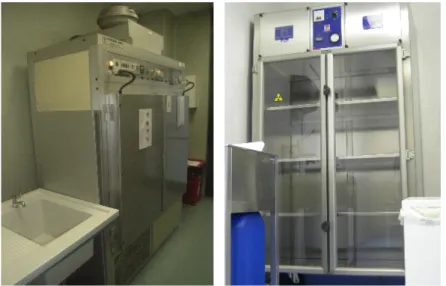
PET/SPECT imaging laboratory, a thick lead container (called “lead pig”) con-taining the vial with the desired activity can be appropriate for dose transporta-tion (see figure 3.2), while a shielded hood or lead shield configuratransporta-tion can be suitable for dose storage (see figure 3.3). On the contrary, when the radiotracers is purchased by an external company, it is supplied in a heavy transportation box (usually 25 kg or more, i.e. see figure 3.3). Given the weight of the trans-portation box, sufficiently strong dollies are recommended to transport the box from the receiving point to the storage place.
• Dose preparation
Once safely stored in a shielded area, the radiotracer needs to be dispensed using a dose calibrator (see figure 3.4). A lead shielding configuration is often used in combination with an L-shaped shield and lead glass window for dose dispensing. A dose carrier, either lead or tungsten, can be used to transport the dose to the injection area. Once injected, the syringe can be assayed for residual activity and disposed of in a shielded sharps container (see figure 3.2). The vial or syringe with the bulk dose can be held until no longer radioactive before disposal.
• Animal radiotracer injection
The injection site varies depending on the species, probe, and experimental design. Rats and mice can be injected via intraperitoneal (ip), tail vein (iv)
![Figure 3.7: Generally accepted source and target distances used for floor and ceiling barrier calculation [90].](https://thumb-eu.123doks.com/thumbv2/123dokorg/7555473.109859/51.892.229.744.435.940/figure-generally-accepted-source-distances-ceiling-barrier-calculation.webp)