U
NIVERSITÀ DEGLI
S
TUDI DI
S
ALERNO
D
IPARTIMENTO DIS
CIENZEE
CONOMICHE ES
TATISTICHES
CUOLAD
OTTORALEI
NTERNAZIONALE“A
NTONIOG
ENOVESI”
D
OTTORATO DIR
ICERCA INI
NGEGNERIA EDE
CONOMIA DELL’I
NNOVAZIONEXI CICLO
T
ESI DID
OTTORATODISK LASER WELDING
OF METAL ALLOYS FOR AEROSPACE
V
ITTORIO
A
LFIERI
TUTOR
Ch.mo Prof. Fabrizia Caiazzo
COORDINATORE
Ch.mo Prof. Alessandra Amendola
INDEX OF MAIN SYMBOLS IX INDEX OF ABBREVIATIONS IX
1 LASER WELDING 3
1.1 Introduction 3 1.2 Applications 4 1.3 Comparison with other welding technologies 4 1.4 Diagnostics in laser welding 6 1.5 Laser safety 7 1.6 Welding robots 8
2 LASER OPTICS AND QUALITY 11
2.1 Introduction 11 2.2 Principles of laser emission 11 2.3 Beam delivery systems 15 2.4 Resonator modes 15 2.5 Laser beam geometry 17
2.5.1 Rayleigh range 19
2.5.2 Beam dependence on the focusing optics 21 2.6 Beam quality 22 2.7 Laser efficiency 25 2.8 Thin disk laser concept 26
2.8.1 Architecture 27
2.8.2 Gain medium 28
2.8.3 Advantages 30
2.8.4 Disk laser vs fibre laser 32
3 PROCESSING DYNAMICS 35
3.1 Introduction 35 3.2 Laser welding modes 36 3.3 Key-hole instability 38 3.4 Gas supply 41
3.4.1 Gas choice 43
3.4.2 Gas supply devices 44
3.5 Focusing 45
3.6 Beam angle 46
4 BEAD CHARACTERIZATION 49
4.1 Introduction 49 4.2 Seam geometry 49 4.3 Non destructive tests 51
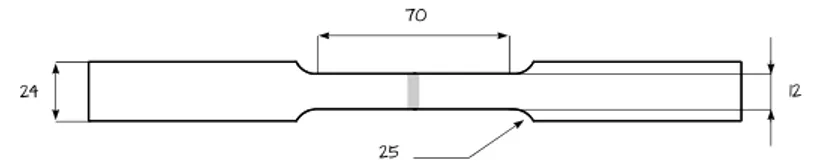
II V. Alfieri, “Disk laser welding of metal alloys for aerospace” 4.4 Sample preparation 52 4.4.1 Cutting 52 4.4.2 Mounting 53 4.4.3 Mechanical preparation 54 4.4.4 Chemical etching 55 4.5 Imperfect shape and dimensions 56 4.6 Assessment of the heat affected zone 58 4.7 Energy dispersive spectrometry 59 4.8 Tensile tests 60
5 MODELING AND OPTIMIZATION 63
5.1 Introduction 63 5.2 DOE principles 63 5.3 Testing schemes 65 5.4 Regression models 67 5.5 Desirability 68
6 WELDING ALUMINUM ALLOY 2024 73
6.1 Introduction 73 6.2 Aluminum welding 74 6.3 Experimental procedure 74 6.4 System set-up 75 6.5 General issues in laser-material interactions 77 6.6 Porosity evolution 79
6.6.1 Thermal input dependence 84
6.6.2 Defocusing effect 85 6.7 Softening in the fused zone 86 6.8 Optimization of butt welded joints 88 6.9 Optimization of lap welded joints 94
6.10 Conclusions 100
7 WELDING TITANIUM ALLOY TI-6AL-4V 103
7.1 Introduction 103 7.2 Arrangement of the experimental plan 104 7.3 Experimental details 105 7.4 Results and discussion 106
7.4.1 Micro structure 108
7.4.2 Main effects 110 7.5 Optimization of the responses 112 7.6 Conclusions 114
8 DISSIMILAR WELDING HAYNES + INCONEL 117
8.1 Introduction 117 8.2 Super alloys welding 119 8.3 Arrangement of the experimental plan 120 8.4 Experimental details 122
8.4.1 Pre welding procedures 122
8.4.2 Post welding procedures 123 8.5 Results and discussion 124 8.6 Optimization of the responses 127
8.6.1 Modeling the response variables 127
8.6.2 Constraint criteria for optimization 128 8.7 Mechanical assessment of the optimal processing condition 129
8.7.1 Vickers micro hardness tests 130
8.7.2 Tensile tests 131 8.8 Conclusions 133
9 DISSIMILAR WELDING HASTELLOY + RENÉ 135
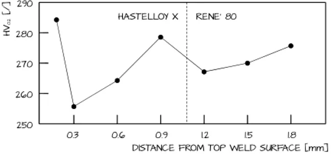
9.1 Introduction 135 9.2 Arrangement of the experimental plan 136 9.3 Experimental details 137 9.4 Results and discussion 139 9.5 Optimization of the responses 141 9.6 Vickers micro hardness tests 144 9.7 Conclusions 144
ACKNOWLEDGEMENTS 147
Laser welding is the logical processing solution to accomplish different needs. Improvements at the design stage are actually aimed to remove any mechanical fastening, thus moving towards a technology which would not increase the joint thickness; moreover, a number of benefits in comparison with conventional welding methods are provided when considering laser beams, since deep penetration is achieved and the energy is effectively used where needed, thus melting the interface to be joined rather than excessively heating up the base metal, which would suffer from thermal distortion and degradation of metallurgical properties otherwise.
Further advantages are achieved in laser welding with thin disk sources, since high output power, high efficiency and good beam quality are simultaneously delivered, unlike traditional laser systems; costs are significantly reduced in comparison with lamp-pumped laser systems. As a consequence, specific interest is shown in aerospace where strict specifications apply.
Nevertheless, a number of issues must be addressed, depending on the material to be welded, as many variables and sub processes concerning fusion and vaporization are involved in laser welding and a delicate balance between heating and cooling is in place within a spatially localized volume. Therefore, extensive studies are required to manage both the stability and the reproducibility of the overall process, before introducing any change in industrial environments. Methods, experimental results and discussions concerning laser welding of common metal alloys for aerospace are provided in this Ph.D. thesis.
A general view of applications and basic advantages of laser welding is first given, with mention to diagnostics and safety. Hence, the principles of laser emission are examined, with respect to the architecture of the sources, beam geometry, quality and efficiency, in order to better portray the benefits of a thin disk laser concept.
Processing dynamics of laser welding are explained afterward, referring to conduction and key-hole mode, instability, gas supply and leading governing parameters such as laser power, welding speed, defocusing and beam angle to be considered in the experimental work. Procedures are provided for proper bead characterization, from preliminary examinations including non destructive
VI V. Alfieri, “Disk laser welding of metal alloys for aerospace”
tests such as fluorescent penetrant inspections and radiographic tests, to sample preparation and eventual mechanical assessment in terms of tensile strength and Vickers micro hardness in the fused zone.
A straightforward description of the design of experiment approach and the response surface methodology is given, so to introduce the testing method to be taken, as well as the steps for data elaboration via statistical tools.
Hence, four case studies about metal aerospace alloys are presented and discussed in their common seam configuration: autogenous butt and overlapping welding of aluminum alloy 2024; autogenous butt welding of titanium alloy Ti-6Al-4V; dissimilar butt welding of Haynes 188 and Inconel 718; dissimilar overlapping welding of Hastelloy X and René 80. All of the welding tests were conducted at the Department of Industrial Engineering at the University of Salerno; a Trumpf Tru-Disk 2002 Yb:YAG disk-laser source with a BEO D70 focusing optics, moved by an ABB IRB 2004/16 robot was employed. When needed, additional tests for the purpose of specific bead characterization were conducted by Avio and Europea Microfusioni Aerospaziali.
As general procedure for each topic, the operating ranges to be examined are found via preliminary trials in combination with the existing literature on the subject. Then, special consideration is given to the processing set-up, the resulting bead profile, possible imperfections, defects and overall features; consistent constraint criteria for optimization of the responses are chosen on a case-by-case basis depending on materials and seam geometry and referring to international standards as well as customer specifications for quality compliance. Optimal combinations of the input welding parameters for actual industrial applications are eventually suggested, based on statistical tools of analysis. Convincing reasons are provided to give grounds to improvements in real applications. Moreover, based on the results, a proper device for bead shielding, to be conveniently adjusted depending on both geometry and materials to be welded has been designed, produced and patented (SA2012A000016).
As concerning aluminum welding, a comprehensive description is given for laser-related issues: reflectivity and thermal conductivity influence on the material response is illustrated; the porosity evolution is discussed with respect to thermal input and defocusing; a theory for softening in the fused zone is provided through energy dispersive spectrometry and estimations of
magnesium content in the cross-section. Optimization is performed for butt configuration of 1.25 mm thick sheets; the discussion about the interactions among the governing factors is deepen with reference to overlapping welding. With respect to titanium welding, optimization is performed for 3 mm thick butt welding; the resulting micro structure in the weld is discussed since it is thought to be closely related to the mechanical properties. In particular, special care is taken of the grain size as a function of the governing factors.
Dissimilar welding of super alloys is considered for gas turbine components; for this specific purpose, laser welding is expected to offer a valid alternative to arc and electron beam welding, whose weaknesses are pointed out. Given their actual application in the engine, Haynes 188 and Inconel 718 are examined in butt welding configuration, whilst an overlapping geometry is preferred for Hastelloy X and René 80. Considerable tolerances are matched, thus promoting the suggested range of the operating variables.
Beam divergence angle θ
Laser wavelength λ
Beam parameter product BPP
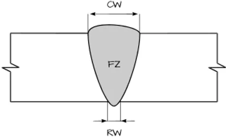
Bead crown width CW
Beam diameter D
Excessive penetration EP
Focus position f
Focal length of the collimating lens fc
Focal length of the focusing lens ff
Extent of the fused zone FZ
Beam irradiance I
Incompletely filled groove IFG
Misalignment M
Beam propagation parameter M2
Bead neck width NW
Laser power P
Penetration depth PD
Reinforcement R
Root concavity RC
Bead root width RW
Sagging S Shape-factor SF Welding speed s Shrinkage groove SG Thickness to be welded t Undercut UC Rayleigh range zh INDEX OF ABBREVIATIONS
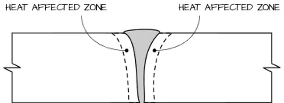
Analysis of variance ANOVA Bead-on-plate BOP Central composite design CCD Design of experiment DOE Electron beam welding EBW Energy dispersive spectrometry EDS Fluorescent penetrant inspections FPI Heat affected zone HAZ Yttrium aluminum garnet YAG Response surface method RSM Radiographic tests RT Transverse electromagnetic mode TEM Ultimate tensile strength UTS
LASER WELDING
1.1 INTRODUCTION
New materials and new processing methods are progressively tested for aerospace in order to meet the challenges of innovation and reduction of operating costs, but extensive studies are needed before introducing any change in industrial environments.
Mechanical assembly are generally preferred because a reduction in waste material is achieved compared with a similar component which is alternatively processed via machining; this trend leads to shorter lead times, as well as lower buy-to-fly ratio, which is a measure of how much material is actually required to manufacture the final flying part. Moreover, joining technologies which do not increase the joint thickness are usually preferred, such that weight reduction is benefited [1]. Hence, improvements at the design stage are aimed to remove any mechanical fastening such riveting in order to introduce welded assemblies.
Laser welding is the logical processing solution to accomplish different needs. As for any other welding technology involving fusion of the materials to be joined, the objective is to create a liquid melted pool, allow it to grow and then to propagate through the solid interface, thus joining the components [2]. Nevertheless, specific issues must be addressed, depending on the material to be welded. For instance, when referring to common alloys systems for aerospace, it has been pointed out that laser welding is hindered by reflectivity and excessive fluidity as well as affected by tendency to porosity in the case of aluminum [3, 4]; brittle phase formation and segregation issues in the case of
4 V. Alfieri, “Disk laser welding of metal alloys for aerospace”
heat resistant super alloys [5]; oxidation and detrimental grain growth when improper welding rates are used in the case of titanium alloys [6].
1.2 APPLICATIONS
A really wide range of applications are regarded to be laser suitable [5]. Laser welding is employed indeed in joining gas turbines components for aerospace, transformer laminates, bimetallic saw blades, stamped mufflers, cooker tops, fire extinguisher cylinders, layered shaving blades, as well as heat-sensitive components such as heart pace-makers; hermetically sealing electronic capsules; repairing of nuclear boiler tubes from the inside; underwater joining. Special consideration has also been given to dissimilar welding, for either the purpose of joining aerospace components which are made of different materials due to machining and operating reasons, or reducing the overall weight of structures. As a result, an effective way to save rare metals is thus provided [7].
Nevertheless, tailored blank joining for car industry [8] is the largest relevant application for laser welding: the process was actually conceived in the eighties and is accepted as the way to handle pressed products. Moreover, when merely considering a car, a wide range of components such as airbag sensors, valve lifters, heat exchangers, gear wheels, torque converters, exhaust pipes, tanks and roof scams are welded via laser beams [5].
1.3 COMPARISON WITH OTHER WELDING TECHNOLOGIES
A number of benefits are provided by laser welding in comparison with conventional technologies. For instance, the process can be performed in remote locations or inside three-dimensional components from single side access, where the introduction of electrodes would be impossible. Furthermore, new opportunities are offered in autogenously joining difficult materials including, but not limited to, aluminum and magnesium alloys without the need for filler metal [2]; no pre heating, neither mechanical finishing are required [9]; increased processing speed is achieved and, as a consequence, productivity improves [10].
Advantages come from the primary feature of narrowly focusing the heat source to a very small area [11], in the order of few tenths of millimetres: local
precision treatment and extremely high cooling rates are benefited, in the order of 104 °C/s whilst a rate of 102 °C/s results in tungsten inert gas welding [12]. Compared with slower processes, grounds are then given to further advantages in dissimilar welding which traditionally is only feasible for certain combinations of the base elements. Indeed, irrespective of the alloys being joined, the properties of different materials are generally difficult to be matched [13] and the formation of brittle intermetallics occurs. Higher cooling rates of laser welding can restrain the issue, such that wider ranges of combinations of metal alloys are offered [5].
Since the welding bead is rarely wide and deep penetration is achieved, it can be seen that the laser energy is effectively being used where required, thus melting the interface to be joined rather than excessively heating up the base metal in the surrounding area, which would suffer from thermal distortion and degradation of metallurgical properties otherwise [2, 9]. In order to give a quantitative description of this concept, the joining efficiency η is defined as:
= ∙ (1.1)
which is not true efficiency, because s is the laser transverse speed, t is the thickness to be welded and P is the incident power, so units of joined square millimetres per supplied joules result. The higher the joining efficiency, the less energy is spent in unnecessary heating which may produce heat affected zones or distortion. Typical values of joining efficiencies of different welding processes [5] are listed in table 1.1: resistance welding is by far the best in this respect because the energy is mainly generated at the high resistance interface to be welded. Nevertheless, both laser and electron beams are in a class by themselves; furthermore, joint access is easier and slighter environmental
TABLE 1.1 – Joining efficiencies of common welding technologies
Process Approximate joining efficiency [mm2 kJ-1]
Oxy acetylene flame 0.2 ÷ 0.5 Tungsten inert gas 0.8 ÷ 2 Manual metal arc 2 ÷ 3 Submerged arc welding 4 ÷ 10
Laser beam 15 ÷ 25
Electron beam 20 ÷ 30 High frequency resistant welding 65 ÷ 100
6 V. Alfieri, “Disk laser welding of metal alloys for aerospace”
impact is produced in terms of noise and fume compared with resistance welding. Therefore, although equipment costs may significantly rise, laser and electron beams are known to play important roles for high quality joints in aerospace, military, power plants and automotive industries [14]: a specific comparison is then worth drawing.
Electron beam welding (EBW) relies on high speed electrons whose kinetic energy is turned into heat upon impact on the piece to be joined. Hence, the process has to be performed in vacuo to prevent energy dissipation of the electron beam [11], whilst laser beam is capable of being used at atmospheric pressure, thus resulting in simple fixturing and reduced lead time [2, 11]. Moreover, X-rays emission arises in EBW and, when specifically considering metal welding, electromagnetic phenomena can produce beam wander affecting stability during material melting [5]; this is obviously excluded in laser welding, with far less tendency to incomplete fusion and spattering [11]. Nevertheless, laser welding systems are usually of higher capital cost compared with conventional welding devices; operating costs can further grow for applications where large flow of expensive shielding gases is required. High production rates and quality are then essential for the system to be competitive and cost effective [2]; in this case, an overall reduction of operating costs ranging from 40 to 50% is estimated in comparison with EBW.
1.4 DIAGNOSTICS IN LASER WELDING
Laser interaction is capable of being manipulated in order to optimize welding. For this purpose, computer control for laser power have been developed. The basic idea is that a variety of signals containing information about the process are generated during the process itself. Extraction and hence recognition of signals is the key to monitoring and adapting control [15, 16]. Actually, each single signal component is adaptable by individual programming via computer numeric controlling system.
With feedback from an optical, plasma or acoustic monitoring system, real time adjustments are hence made to the power level in order to compensate possible changes in the welding conditions. Imperfections which could result in rejection at quality checks are thus fixed. Such closed loop controllers rely on excellent understanding of the process; optimal welding is performed in turn without any operator intervention.
The most simple monitoring procedure is conducted visually, referring to direct imaging of the weld pool and the surrounding area on the work-piece during the process. Oscillations of the weld pool take the form of surface waves of appreciable amplitude, ranging between 200 and 300 Hz; referring to steel welding, frequency has been proven to dramatically increase to one order of magnitude more when unstable conditions are in place [2].
1.5 LASER SAFETY
Laser devices are potentially dangerous when improperly used [11, 9] because exposure under certain circumstances may result in damage for the human body. Classes of lasers, depending on both the power and the wavelength of the emitted radiation, are hence defined in ANSI Z136 for the United States and IEC 60825-1 internationally, based on the potential for causing immediate injury. Common lasers for welding and cutting are infrared indeed; therefore, since the beam light may be invisible to the human eye, precautions could be difficult to be taken; even more difficult could be convince people to take precautions against possible hazards they may not understand [17].
The main source of danger of a laser beam is the light radiation which could be easily reflected by the work-piece, especially when processing metals, and could quickly produce in mild skin burns as well as irreversible injury to skin and eyes. It is now widely accepted that the skin is far less vulnerable than the eye, the former being provided with an external protective layer of dead cells, whilst an ocular focusing effect applies when a mirror-like reflection enters the eye. Special shielding devices in the form of spectacles or goggles with proper filtering optics, to be labeled with both the optical density and the wavelengths they are suitable for, are then required to protect the eyes, according to international standards.
Opaque barriers are needed anyway for the purpose of safety around the processing area; although designed to offer a wide range of protection, barriers do not normally withstand high welding energy radiations for more than few seconds, without some damage including the production of smoke and open fire. Additional non beam hazards, which are associated with the use of lasers although not being directly dependent on the beam itself, can be life threatening. Since high energy levels are delivered, possible hazard of fire must be addressed; hence, any flammable material is required to be kept away from
8 V. Alfieri, “Disk laser welding of metal alloys for aerospace”
the processing area; also, any reflected beam could start fire in unexpected places.
Adequate ventilation is needed as fumes are produced during the process. Eventually, given that a relative motion is in place between the laser beam and the work-piece, moving bits are additional source of risk.
1.6 WELDING ROBOTS
Three-dimensional welding of car and aircraft components is often required. Since most welding processes are not capable of being well enough controlled for three-dimensional manipulation and monitoring, robot-assisted laser welding heads are usually employed to move the beam along the welding path [5, 18]. On the other hand, for the sake of competitiveness, manual welding in modern industries must be limited to few operations, due to many further reasons such as long set-up time, operator discomfort, safety issues and resulting costs. Additionally, the optimized welding condition must be maintained during the process and must be reproducible over a series of welds to be performed [2].
Therefore, industrial robots are essential components and specific tasks as assembly operations and materials handling are addressed in repetitive manner at acceptable cost and quality levels: in particular, it has been estimated that as much as 25% of all industrial robots are specifically employed to weld and the most active industry in their application is the automotive [10]. For safety reasons, welding robots become a need with laser sources which are recognized as being potentially dangerous.
Robotic welding has undergone severe evolution. A first generation of welding robots had been developed in the early sixties as two-pass system, since a first pass is needed in order to learn the seam geometry and the welding path, whilst the second pass is the actual welding one: the working space is properly structured such that the robots can easily move along predetermined paths. On the other hand, a second generation of welding systems had been introduced in the seventies to track the seam in real time, with simultaneous learning and welding, thanks to a combination of both mechanic and electronic devices to identify any possible obstacle within the working space. Further advantages had been achieved in the eighties with third generation welding robots which actively fix their movements and compensate any changes in
position and orientation of the work-piece; they are capable of being used for point-to-point as well as continuous motion to be settled off-line, with additional high-level diagnostic capability to report about failures and maintenance [19]. In this case, great flexibility is accomplished, at the expenses of a considerable amount of programming work of high-skilled operators [10].
LASER OPTICS AND QUALITY
2.1 INTRODUCTION
Laser sources of high reliability are required to weld metals on a commercial basis. In addition to typical benefits of laser beam welding above conventional technologies, several further advantages are achieved when using thin disk sources, because high output power, high efficiency and good beam quality are simultaneously delivered, unlike traditional laser systems [20]. Disk lasers had been pioneered in the nineties by Adolf Giesen at the University of Stuttgart and have been enhanced for serial production after being offered as commercial products from different companies [21]. One particularly successful implementation had been first developed by Volkswagen to weld the Passat rear shelf and has been given approval for serial production in December 2005: in a detailed examination of the economic viability of the process, the operating costs of the thin disk laser were significantly reduced in comparison with previous lamp-pumped systems [22].
2.2 PRINCIPLES OF LASER EMISSION
Laser is the acronym for light amplification by stimulated emission of radiation, since the beam is produced by an electromagnetic radiation emission in a specific solid, liquid or gaseous material which is called the gain medium, or the active laser medium, whose atoms are moved to higher energy levels as a consequence of absorbing stimulating energy.
Some external supply of energy in the form of bright light, electric current or chemical reaction is required to pump the gain medium. In particular, when
12 V. Alfieri, “Disk laser welding of metal alloys for aerospace”
light is injected to electronically excite the medium, optically pumped lasers are obtained [23]. In general, excited states are produced in the atoms, since the electrons which are in the nearest possible orbits to their nucleus move from the ground state to outer orbits. Excited states are generally not stable: therefore, when the electrons drop from a higher energy level to lower one, extra energy is emitted in the form of a photon and light is produced. The process occurs as spontaneous emission when the electron naturally decays into a lower level, without outside intervention; the photon is then emitted in a random spatial direction. Its frequency ν is shaped by the rules of quantum mechanics, being E1 the energy of the lower level, E2 the energy of the higher one and h the Planck’s constant:
= −
ℎ (2.1)
The resulting wavelength λ of the emitted photon is given by:
= (2.2)
where c is the speed of light in vacuo. Stimulated emission takes place instead when the incoming input photons with suitable energy or optical frequency enhance the emission; in this case, any emitted photon has the same phase, wavelength and direction of the passing one [24, 25]. Therefore they are: coherent with respect to each other, with peaks and valleys moving together through time and space; monochromatic, consisting in one single color; and parallel with little spread. For such specific features, a laser beam differs from ordinary light.
As long as the lower energy states prevail over the higher states, stimulated emission is prevented, since emitted photons are absorbed to raise an electron from a lower energy configuration to a higher one, instead than stimulating a drop of energy. On the contrary, when the number of excited electrons exceeds the number of electrons in the ground state or in a less excited state, population inversion is achieved and higher energy configurations predominate, so spontaneously emitted photons are more likely to stimulate further emissions, thus generating a cascade of photons [24]. For this condition to be fulfilled, the gain medium must therefore be pumped over the lasing threshold; hence, the stimulated emission prevails against the spontaneous one, thus allowing an amplification of the incoming radiation [23].
FIGURE 2.1 – Three-level system for laser emission
The basic conceivable system has only two energy levels, which are not enough anyway for population inversion, because an eventual equilibrium is achieved between absorption and stimulated emission, with equal number of electrons on each energy state, resulting in optical transparency and actually no net optical gain. Three levels at least are then required to produce non equilibrium conditions: referring to figure 2.1, the gain medium is first excited to a short-lived high energy state which spontaneously and rapidly drops to a somewhat lower energy metastable state trapping and holding the excitation energy to be used for laser emission when further dropping to the ground state.
As light is emitted, electrons accumulate in the ground state, so the gain medium needs to be strongly pumped in order to keep population inversion. This difficulty is overcome with four levels, where an additional short-lived transition state is located before the ground one, as shown in figure 2.2. A rapid energy drop is in place between the lower laser level and the ground state, so population inversion between the higher laser level and the lower one
FIGURE 2.2 – Four-level system for laser emission
GROUND STATE E2 E1 LASER EMISSION GROUND STATE E3 E2 LASER EMISSION E1
14 V. Alfieri, “Disk laser welding of metal alloys for aerospace”
FIGURE 2.3– Resonant cavity scheme for laser emission
is heavier compared with three-level lasers. Furthermore, few atoms must be excited into the upper laser level to produce population inversion; therefore four-level lasers are much more efficient. A quasi-three-level gain medium provides an intermediate configuration, where high pumping densities are needed anyway because the lower laser level is close to the ground state which is formed by a certain number of thick sub levels. Notably, irrespective of the number of levels, the energy gap for pumping transition is greater than the energy gap of the laser transition, so when optically pumping the gain medium, the pumping light frequency has to be greater than the resulting laser one, both of them to be in agreement with equation (2.1), depending on the energy levels being considered. Consequently, the pumping wavelength is shorter than the laser one.
A resonant cavity which allows to build up light energy, increasing its intensity in order to generate a beam is required. Otherwise any gain medium would just be an optical amplifier to enhance light from an external source. As shown in figure 2.3, an optical resonator is composed by placing the gain medium between a pair of mirrors which face each other such that the emitted light is reflected back and forth, thus improving the uniformity of the emitted photons. One of the mirrors is generally only partially reflective, so to transmit a fraction of the incident light [24] to form a narrow beam which is suitable for several applications.
Basically, two emission modes make the relevant distinction between laser systems: continuous wave and single pulsed. When working in continuous wave emission, a stable adjustable average beam power is delivered; on the other hand, in case of pulsed operation the output takes the form of pulses of light on the time scale. Versatile lasers can be operated in both modes since a
GAIN MEDIUM PUMPING SOURCE LASER BEAM PARTIALLY REFLECTIVE MIRROR TOTALLY REFLECTIVE MIRROR
source whose output is normally continuous can be intentionally turned on and off at some rate in order to create pulses of light; nevertheless, specific lasers outputs are only pulsed because the gain medium cannot be run in continuous mode [23]. Customized pulse shapes are often useful in optimizing welding, particularly when spot welding aluminum alloys [2].
2.3 BEAM DELIVERY SYSTEMS
Two possibilities are allowed to eventually deliver the laser beam from the resonant cavity to the processing location: free space propagation through oscillating mirrors and lenses, or flexible optical fibre cables [9, 18, 26]; additional integrated beam switches are capable of managing up to six different outputs in the same delivery device [22].
When using high quality optics for free space propagation, laser quality is not significantly affected although any required device is complex, expensive, often bulky and difficult to maintain. Ideal delivering is therefore offered by fibre cables when considering complex processing paths or complicated manipulation of the optics; up to several hundred metres long cables are available, being them particularly suitable for assisting robots [27].
Whichever the chosen solution, the concept of laser sources and their beam delivery system as separate entities is abandoned in state-of-the-art equipments, in favour of an integrated approach which combines all of the elements for laser generation and beam delivery into a single system whose performances are optimized for the specific joining application [2].
2.4 RESONATOR MODES
The intersection between a generic plane and the laser beam produces the beam spot, which is a circle when the plane is orthogonal to the beam propagation axis and the beam shows circular symmetry for any possible cross-section. The architecture of the resonant cavity affects the light intensity distribution within the spot, because the energy is built up in specific locations at the expense of others; that is to say, it is possible to achieve a maximum value at the centre of the spot, or else to evenly allocate the energy.
The power of electromagnetic radiation per unit area is the radiative incident flux on a surface and is referred to as irradiance.
16 V. Alfieri, “Disk laser welding of metal alloys for aerospace”
FIGURE 2.4 – Transverse electromagnetic modes, as resulting from Hermite-Gaussian solutions
Its profile in the beam cross-section is described through the resonator mode or transverse electromagnetic mode (TEM) which is normally denoted as TEMmn where subscripts m and n stand for the number of minimum values in
the irradiance distribution along generic orthogonal x and y directions, respectively [9]. With this rule, possible profiles of irradiance resulting from the Hermite-Gaussian solutions to the equation of electromagnetic propagation [28] are shown in figure 2.4. The fundamental TEM00 mode apply for any laser source featuring a beam with no minimum; its only irradiance peak locates on the beam propagation axis at the centre of the cross-section and a Gaussian transverse profile of irradiance is thus produced along any possible direction, thus regardless of the angular coordinate, as shown in figure 2.5. A laser operating on a single type of resonator mode, which is almost always a Gaussian one, is referred to as single-mode [23]. As a function of the r position from the cross-section centre, the irradiance distribution in a polar coordinate system has the form:
( ) = ∙ (2.3)
where I0 the peak irradiance and R the beam radius, which needs to be defined
FIGURE 2.5 – Beam irradiance distribution as a function of distance from beam centre
X Y X Y X Y X Y
TEM00 TEM01 TEM10 TEM11
in some way because the irradiance continuously decays to zero at a distance from the beam centre [28]. The common form (2.3) actually comes as a consequence of conventionally accepting the beam radius as being the finite distance where irradiance drops of e2 with respect to its peak [29], based on the second moment of the intensity distribution [23]. Thus:
( ) = 1 ∙ = 0.135 ∙ (2.4) Namely, the beam irradiance at the beam radius R falls to 13.5% of its peak; therefore, as much as 86.5% of the total irradiance is held within a circle of radius R. The beam diameter is eventually defined as twice the beam radius.
2.5 LASER BEAM GEOMETRY
In order to compare different laser sources, a general understanding of the nature of the laser output is needed. As shown in figure 2.6, any laser beam draws a rotational hyperboloid of one sheet [9]: moving along the propagation axis, it shows convergent geometry towards the beam waist, which is intended to be the location where the minimum diameter D0 or the beam focus diameter is achieved and the optical wave-fronts are flat [23]; then, the beam diverges again with symmetrical trend with respect to its focus.
A reasonable approximation of the asymptotic variation of the beam radius expanding from the waist towards the far field is provided by a conical shape whose aperture angle θ is considered to be the beam divergence angle or the angular spread. The beam expanding from its waist gives rise to a caustic curve whose analytical expression [9] has the form:
( ) = + ∙ (2.5)
FIGURE 2.6 – Symmetrical trend of beam propagation with respect to its waist
D0
BEAM WAIST
18 V. Alfieri, “Disk laser welding of metal alloys for aerospace”
which gives the beam diameter D at a certain location z from the focus point, on the propagation axis, depending on divergence angles in the order of tenths of radians. Nevertheless, considering the approximation in the far field, the beam diameter at proper distance from the focus point can be obtained from:
∞
2 ∙ ∞
= tan
2 (2.6)
Hence, for small divergence angles, this yields:
∞= ∞∙ (2.7)
If a lens focuses a laser beam, a new waist with different focus diameter as well as a new far field divergence angle are formed. This happens in a way that constancy is in place for their product, provided that ideal aberration free optics are used [5, 9]. Stronger focusing then leads to higher divergence angles [23]. In particular:
∙ = ∙ (2.8)
where N is the refractive index of the material which light is travelling through; it is normally neglected for propagation through air [9], being it 1.0003. Therefore:
∙ = ∙ (2.9)
On the other hand, light wavelength λ depends on the active gain for laser emission, whilst k is a constant to take account of the irradiance distribution whose mode then affects the beam geometry. Light wavelength depends on the energetic levels of the specific gain medium; corresponding values for a number of lasers are listed in table 2.1. As for k, a Gaussian beam yields:
=4 (2.10)
and lower values are not possible due to diffraction effects. As a consequence, the resulting divergence angle θG is:
= 4 ∙
TABLE 2.1 – Operation wavelengths and pumping sources for a number of lasers
Gain medium Laser type Pumping source Operation wavelength [μm]
Excimer Gas Electrical discharge 0.193 ÷ 0.353 Nitrogen Gas Electrical discharge 0.337 Gallium nitride Semiconductor Electrical discharge 0.400 Ruby Solid state Flashlamp 0.694 Ytterbium glass Solid state Laser diodes 1.000 Ytterbium YAG Solid state Laser diodes 1.030 Neodymium glass Solid state Laser diodes 1.062 Neodymium YAG Solid state Laser diodes 1.064 Oxygen iodine Chemical Chemical reaction 1.315 Thulium YAG Solid state Laser diodes 2.000 Holmium YAG Solid state Laser diodes 2.100 Erbium YAG Solid state Laser diodes 2.940 Carbon dioxide Gas Electrical discharge 10.60
which is the lowest value a laser beam may ever achieve for a given waist diameter. Since a limit is thus imposed on the beam divergence, Gaussian laser beams are said to be diffraction-limited and are therefore deemed to be ideal. 2.5.1 RAYLEIGH RANGE
From the caustic equation (2.5), as well as from its asymptotic approximation in the far field (2.7), it is clear that low divergence angles allow to better restrain the diameter expansion along the propagation axis. Beams with very small angle spreads, such that their diameter is approximately constant over significant propagation distances, are called collimated beams. Nevertheless, in order to effectively weigh up the diameter constancy, a quantitative measure must be referred to. The Rayleigh range is usually considered, being it the distance from the beam waist, in the propagation direction, where the beam diameter expands although remaining below a threshold value Dh which is
given by:
= ℎ ∙ (2.12)
where h is positive arbitrary [9]. The corresponding Rayleigh range zh is
therefore obtained from the caustic equation (2.5):
20 V. Alfieri, “Disk laser welding of metal alloys for aerospace”
Given the symmetry of a laser beam, the total distance for the beam to be considered as collimated is the double Rayleigh range, which is measured across the focal point and is referred to as the depth of focus or, according to older literature, the confocal parameter [23]. Equation (2.13) suggests that, irrespective of h, high divergence angles are detrimental for the purpose of collimation; moreover, it is not possible to benefit from both small focus diameter and large depth of focus at the same time. The most common value for h to determine the Rayleigh range is the square root of 2 because the doubling of the focus spot is thus produced. Then, equation (2.13) yields:
√ = (2.14)
and the caustic equation (2.5) alternatively becomes:
( ) = 1 + ∙ ⇒ ( ) = ∙ 1 +
√
(2.15)
A much more restrictive value of 1.05 is used sometimes for h to calculate the distance over which the beam diameter spreads of 5% with respect to the focus. From a technological point of view, high depth of focus are desirable and often crucial for certain welding conditions because the threshold irradiance must be overcome through the entire thickness of the work-piece aiming to perform a deep penetrative welding; therefore, a depth of focus which is too short with respect to the thickness, may not be adequate to effectively perform the process [9].
As one may expect, the Rayleigh range is affected by the beam irradiance distribution also, since a dependence on the TEM profile is embedded in the Rayleigh range as a consequence of product constancy between D0 and θ, as shown in equation (2.9). Therefore equation (2.14) yields:
√ = ∙ (2.16)
The largest possible Rayleigh range is then achieved when considering a Gaussian beam, having it the lowest k value:
√ = ∙ =
∙
In this sense, the benefit of an ideal Gaussian beam is once again pointed out in terms of its depth of focus.
2.5.2 BEAM DEPENDENCE ON THE FOCUSING OPTICS
When a laser beam is delivered via optical fibre, as shown in figure 2.7, it expands as soon as it exits the cable, since it is no longer constrained by the internal light reflections within the fibre; therefore, it needs to be focused again. This is performed using a pair of lenses which are, in the order the beam meets them, a collimating one to align the beam and a focusing one to achieve smaller diameters [9]. With the assumption of aberration free optics, the product between the waist diameter and the far field divergence angle is the same when measured either at the collimating side or the focusing side. Being
DF the fibre core diameter, which is actually the waist diameter at the
collimating side, and θC the corresponding divergence angle, the constancy
condition is written as:
∙ = ∙ (2.18)
In the case of light sources at infinite distance or reduced beam divergence, the distance between the lens and its corresponding focus point is roughly equal to the focal length. As the beam diameter DL between the lenses is achieved in
the collimating far field at a distance fC from the focal point, as well as in the
focusing far field at a distance fF from the focal point, equation (2.7) yields:
= ∙ (2.19)
= ∙ (2.20)
Hence, the far field divergence angles are in inverse proportion to the corresponding focal lengths:
FIGURE 2.7 – Beam delivering via fibre cable and corresponding focusing scheme
D0
DL
fC fF
COLLIMATING LENS FOCUSING LENS
DF
22 V. Alfieri, “Disk laser welding of metal alloys for aerospace”
∙
∙ = 1 ⇒ = (2.21)
When combining this result with equation (2.18), the resulting downstream focus diameter D0 is found to be dependent on both the focal lengths:
= ∙ (2.22)
so the beam is delivered with the fibre core diameter if lenses with the same focal length are employed. Interesting additional conclusions are drawn when considering the impact of the focusing lenses on the Rayleigh range, which is then given by equation (2.14):
√ = = ∙ (2.23)
This suggests that the proper focal length in the focusing optics must be chosen with respect to the process to be performed: as a consequence of equation (2.22), smaller focus diameters, and thus higher beam irradiances, are implied by a shorter fF which, on the other hand, imposes a shorter depth of focus and
a higher angle spread.
2.6 BEAM QUALITY
Different ways are commonly used to refer to laser beam quality, which essentially is a measure of how tightly a laser beam can be focused with limited beam divergence. Indeed, narrow spots are crucial to prevent irradiance reduction for all of the applications such as printing, marking, welding, cutting and drilling where strong focusing of the beam is required [23], with the exception of variable gapped seams which are difficult to be tracked so that a wider beam would be easier and more reliable to be used [5]. On the other hand, surface treatments are less critical since larger spots are required; poor beam qualities are then satisfactory anyway.
The index which is normally used to refer to beam quality is the beam parameter product (BPP), being it the product of the beam radius R0 at the beam waist with the far field beam divergence half-angle α:
= ∙ =
2 ∙2= ∙
which makes sense because it has been proven that constancy is in place for any given beam for the product between the focus diameter and the divergence angle, although non ideal optics can spoil the beam quality and thus increase the BPP. Hence, considering equation (2.9):
= ∙
4 (2.25)
Usual units for BPP are millimetres times milliradians; non circular beams provide different values for BPP depending on the considered direction to measure the spot contour. For the purpose of beam quality, the higher is the
BPP, the lower is the beam quality. Alternatively, focusability φ is intended to
be the ability to achieve a small focus diameter with a given optical element; it is defined as the inverse BPP [30]:
= 1 = 4 (2.26)
Ideally, considering the divergence angle of a Gaussian beam in equation (2.11), the smallest possible value for BPP is given by:
= ∙
4 = 4 ∙ 4 ∙
∙ = (2.27)
Since the output from real lasers is unfortunately not truly Gaussian, although very close, an additional beam quality index, the so called M2 factor or beam propagation parameter, is introduced to accommodate this variance [28, 29]. It is defined as the laser BPP divided by the corresponding ideal BPP of an equivalent Gaussian beam with the same wavelength; it is therefore a dimensionless quantity. Considering equation (2.27):
= = = ∙ = ∙
4 (2.28)
In this sense, M2 takes account of the deviation of a laser beam from a theoretical Gaussian one which yields:
= 1 (2.29)
Lower values are not possible: for high energy lasers, the M2 factor can be as high as 1000 [23]. A relation is drawn between M2 and the divergence angle
24 V. Alfieri, “Disk laser welding of metal alloys for aerospace”
when combining equations (2.4) and (2.8): =4 ⋅ ⋅
∙ (2.30)
The laser spread then depends on the irradiance distribution: the higher is the
M2 factor, the lower is the beam quality, since higher divergence angles are obtained, other parameters being taken as constant. This has obvious impact on the Rayleigh range as well, which is decreased by the M2 factor with respect to the corresponding value of a Gaussian one [23] for those beams with imperfect beam quality. Indeed, when considering its form in the equation (2.14), the Rayleigh range becomes:
√ = = 4 ⋅ ⋅ ∙ = ∙ 4 ∙ ∙ 1 = √ (2.31)
Although smaller fibres for beam delivery produce less degradation of beam quality, it has been pointed out that the minimum fibre core diameter to be used is in direct ratio with the beam propagation parameter, any other factor taken as constant [27].
For certain industrial applications, the generation of high power is not enough, as high brightness is required [31]. With respect to laser technology, brightness
B is a measure of the maintenance of intensity while a beam propagates from
its focus; it is intended in a quantitative sense and is generally understood as being equivalent to its radiance, which is the total power P divided by the product of the focus area A0 and the solid angle Ω in the far field [23]:
=
∙ Ω (2.32)
Brightness is usually expressed in watts per square millimetres per steradians. It can be related to M2 since:
=
( ∙ ) ∙ ( ∙ )= ∙ = ∙ (2.33) and is therefore considered to be a better indicator compared with raw power, because high brightness means high power at good beam quality. Hence, high quality is crucial when power is limited and high irradiances are required
anyway [27]. Although the output power is lower than the pumping one, laser beams resulting from gain medium pumping show much higher brightness compared with the pumping source; in this sense, lasers are usually referred to as brightness converters [23].
2.7 LASER EFFICIENCY
Performances of optically pumped lasers are judged in terms of efficiency, and their power is compared [32]. When considering the total expense of a laser system in terms of electricity bill, the wall-plug efficiency has to be referred to, being it the total electrical-to-optical power efficiency. Taking the term seriously, the electrical power should be measured at the wall-plug, so that the efficiency includes both losses in the power supply and any power term for cooling, which can be significant for high power lasers. Hence, the demands on electrical installations and in turn the size of the overall system are reduced when higher wall-plug efficiencies are in place. However, it is common practice to account the wall-plug efficiency as based on the electric power to the laser diodes, thus neglecting the actual wall-plug [23].
Purely considering the optical features, the slope efficiency or the differential efficiency is alternatively defined as the slope of the curve of laser output versus pumping power; usually, once crossed the threshold pumping power, the curve is close to linear, so that slope efficiency as a single number effectively makes sense. The output power trend as a function of the pumping power is shown in figure 2.8. The threshold pumping power is 5 kW and the slope efficiency is 50%: this leads to 0.5 W additional output for each additional watt of pumping power above the threshold.
FIGURE 2.8 – Output power trend as a function of the pumping one
PUMPING POWER [W] 0 5 10 15 20 25 0 5 10 15 O UT P UT P O W ER [ W ]
26 V. Alfieri, “Disk laser welding of metal alloys for aerospace”
FIGURE 2.9 – Optical-to-optical laser efficiency as a function of the pumping power
However, non linear curves can result under certain circumstances, for example when considering a quasi-three-level gain medium; furthermore, a laser may even stop working for too high pumping powers, when the stability zone of the laser resonant cavity is left, due to excessive thermal lensing effect. In case of such non linear curves, the slope efficiency is often determined via approximation. The optimization of the laser output power for a given pumping power usually involves a trade-off between high slope efficiency and low threshold pumping power.
The raw ratio of the output power to the pumping power is the optical-to-optical laser efficiency; the resulting shape of the curve is given in figure 2.9 and depends on the slope efficiency as well as on the threshold pumping power.
2.8 THIN DISK LASER CONCEPT
The thin disk laser is a diode-pumped solid state laser, since its base concept rely on a solid state gain medium which is pumped via diodes [20, 31]. As for any other high power solid state laser, the challenge in designing a successful device is how best to deal with the inevitable generation of waste heat as a consequence of the pumping process. Inadequate thermal management results in imposing a limit on the laser output power and deterioration of beam quality [31]. Indeed, non uniform deposition of heat is typical of diode-pumped solid state lasers, so temperature gradients are set up through the gain medium which is hotter on the beam axis, compared with the outer regions [32], typically causing some transverse variation in the refractive index which is temperature dependent [23]. A thermal lensing effect is then induced because
PUMPING POWER [W] 0 5 10 15 20 25 0 20 40 O P T -O P T E F F IC IE N C Y [% ]
the gain medium acts as a real lens, thus increasing the beam divergence. Additionally, thermal gradients are also reason for differential thermal expansion within the gain medium: bulging faces are produced in cylindrical rod or slab laser, with consequent enhanced lensing effect and thermal stresses which eventually lead to thermally induced fractures in the gain medium [31].
2.8.1 ARCHITECTURE
In order to mitigate the detrimental consequences of heating up the gain medium, intensive research over a number of years has been conducted both on geometry and materials. It has been pointed out that the distance the heat must flow through the gain medium must be reduced, as far as possible; moreover, a geometry which would minimize the effect of any optical change in the laser field must be chosen.
The thin disk laser design arises as natural consequence: the core concept of the principle is a thin and disk-shaped gain medium. A short axial dimension is achieved in comparison with the radial extent: the disk is 100 to 200 μm thick, depending on the specific material of the gain medium [20]; the diameter ranges from 10 to 20 mm instead, depending on the power level [22]. The pumping beam, whose spot diameter is significantly larger than the thickness of the disk [31], is incident on a large gold-coated parabolic mirror which provides longitudinal excitation of the disk and allows beam propagation downstream via its on axis hole.
A side view for the architecture of a thin disk laser system is shown in figure
2.10. The disk is fasten to a heat sink which provides cooling by water
impingement thanks to several nozzles inside [33].
FIGURE 2.10 – Thin disk laser design: side view for architecture and pumping
LASER BEAM HEAT SINK DISK PUMPING RADIATION PARABOLIC MIRROR SOLDER
28 V. Alfieri, “Disk laser welding of metal alloys for aerospace”
Hence, cooling of the disk occurs through the back-side flat face which is also used as the ending mirror in the resonant cavity and is properly coated to be highly reflective at both the pumping and laser wavelengths, whilst the other face is provided with an anti reflective coating to both wavelengths [31], so that the disk behaves as an active mirror itself [23].
The advantage which naturally comes when cooling through a large face of a thin slice of material is that the ratio of the cooled volume to the cooling surface area results to be small, as indeed is the distance the heat must flow to reach the heat sink. In such this shape, the gain medium is aggressively cooled: since the direction of the heat flow is parallel to the short axis of the disk, the heat load is uniform in the transverse direction where, as a consequence, the excursions of temperature are minimized; this results in purely axial gradients which in turn imply the intra cavity field experiencing no thermal lensing [31]. Compared with a rod laser geometry, where cooling is essentially managed in the radial direction [32], variations in the refractive index profile are reduced by more than one order of magnitude [20], with minimal distortions of the wave-front [21].
Issues of thermal expansion within the gain medium are not removed at all because cooled and non cooled surfaces still experience different thermal fields, as a consequence of axial temperature gradients. This leads to bowing the disk and hence to a curved resonator mirror which is the dominant effect of the thermal distortion affecting the laser emission in the effective absence of classical thermal lensing effect [31]. It is clear that fastening of the disk to the heat sink is the key engineering step in the manufacture of the resonant cavity; it is equally clear that extensive discussions about the topic are not available in open literature. Nevertheless it has been suggested that indium-tin or gold-tin solders are being used in the highest power systems to join the disk to the heat sink: a very stiff fixation without deformation of the disk is obtained. Furthermore, in order to reduce any possible stress during and after the soldering process, the heat sink is made of a heat expansion matched Cu-W based alloy [33]. Additionally, in order to facilitate the joining, few dielectric layers are usually employed for back-side disk coating [31].
2.8.2 GAIN MEDIUM
Several materials were considered in research to manufacture the disk laser gain medium. Convincing results were achieved exploiting ytterbium (Yb),
which is a bright, soft, silvery-white metal in the group of rare earth elements. Solid state gain medium with interesting optical properties are obtained when ytterbium is used as doping agent in a synthetic crystalline material such as yttrium aluminum garnet (YAG), thus resulting in Yb:YAG laser sources [31, 33] with 1.03 µm emitted wavelength (cf. table 2.1), which is therefore outside the visible spectrum for the human eye. A pumping wavelength of 0.94 µm is generally used [23]. Typical doping concentrations in rare earth doped crystal are specified in atomic molar percentage (at.%) of the doping element [23]; an optimal 9 at.% concentration was suggested for Yb:YAG disk-lasers [20, 31]. A primary advantage is achieved with ytterbium doping since heat loading in the gain medium is almost three times lower compared with neodymium (Nd) doping [31]; moreover, benefits result from no parasitic effects such as up-conversion fluorescence, which takes place when the emitted wavelength is shorter than the exciting one; and cross relaxation, which is due to part of the energy of an excited electron being transferred to another one in the ground state, so that both electrons end up into an intermediate level [23].
However Yb:YAG gain medium is a quasi-three-level system; therefore high power densities are needed for the pumping process to reach the lasing threshold [34]. Moreover, depending on the thickness and the doping level of the disk, only a small fraction of the pumping radiation is absorbed [34]. The specific architecture of the resonant cavity allows to overcome the issues and a scheme of multiple pumping beam passes through the disk is used. Indeed, thanks to steering optics, unabsorbed pumping radiation is collimated again on the opposite side of the parabolic mirror, then focused onto the disk, from another direction. Theoretically, the process can be repeated until all of the virtual positions of the parabolic mirror have been used, so that 16 to 32 passes of the pumping radiation through the disk are realized and more than 90% of the diode power is absorbed.
The limit for the possible number of pumping passes is given by the diodes beam quality which determines the beam diameter on the parabolic mirror and hence the number of positions on the mirror which can be effectively used for redirection. The better is the beam quality of the pumping diodes, the higher is the number of possible pumping passes and the higher the total optical-to-optical efficiency of the thin disk laser [20]; as a consequence, the thickness of the disk can be further reduced as well as the ytterbium doping concentration [20, 31].
30 V. Alfieri, “Disk laser welding of metal alloys for aerospace”
2.8.3 ADVANTAGES
Each component of the optical beam path from the laser source to the focusing optics contribute to the overall reliability of the application in its specific industrial environment. In this sense, thin disk lasers provide higher level of reliability and are then integrated in many production lines [22]. Indeed, diode pumping is considered to be a prime key advantage over lamp-pumped lasers, as longer lifetime of the pumping devices is benefited [23].
Moreover, as a consequence of multiple pumping beam passes through the disk and the specific architecture of the resonant cavity, so that light leaks around the mirrors are not amplified, any loss within the optical resonator is reduced [24]. Therefore, lower electrical power supplies are needed: this results in high wall-plug efficiency, in the order of 25% for industrial lasers with 8 kW output power; more than 5.3 kW have been achieved with a maximum optical-to-optical efficiency of 65% [33].
With respect to a mere technical point of view, the raw output power must be considered and adequately improved. Power scaling in laser design involves any procedure to achieve substantially increase in the optical output [23]. As no classic thermal lensing effect is experienced in the disk, the primary thermal limitation to power scaling is removed [31]: since the first demonstration of the principle, the output power of one single disk could be increased to more than 5 kW in continuous wave operation indeed. By arranging a series of four disks in the same resonator, an output power extraction of more than 9 kW is benefited [20, 22].
FIGURE 2.11 – Laser output power and optical efficiencies as function of pumping spot diameters
PUMPING POWER [W] 0 200 400 600 800 1000 0 100 O U T P U T P O W E R [ W ] 200 300 400 500 600 O P T -O P T E F F IC IE N C Y [% ] 10 20 30 40 50 60 0 1.2 mm 2.2 mm 4.8 mm 6.0 mm
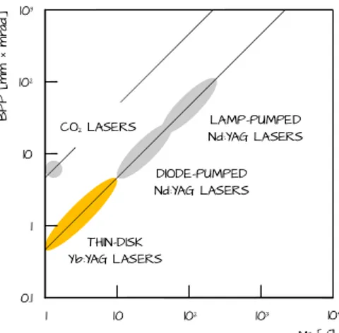
FIGURE 2.12 – Beam parameter product versus M2 values for a number of lasers
However, in general, simple power scalability in single disk lasers sources is achieved just by increasing the pumping beam diameter, with no need for increase in diode brightness; laser power results for 16 pumping beam passes of different spot diameters between 1.2 and 6 mm onto a 9 at.% doped Yb:YAG disk are shown in figure 2.11. The slope efficiency and the optical-to-optical efficiency curves are similar among the examined conditions; nevertheless, being the lasing threshold proportional to the pumped area on the disk, it increases with increased pumping spot diameter [20].
In terms of beam quality, for a better comparison of laser sources, beam parameter product versus M2 values for a number of laser types are shown in
figure 2.12, so to simultaneously consider both the operation wavelength and
the irradiance distribution. Due to longer wavelength, it is clear from equation (2.25) that CO2 lasers have a larger BPP than both ytterbium or neodymium solid state lasers, but still compare favourably with lamp-pumped systems [23]; anyway, thin disk Yb:YAG lasers noticeably offer the best BPP to M2 coupling. Larger Rayleigh ranges are then achieved: this allows to get a reproducible weld which does not depend on perfect control of the focus position [26]. Since working distances increase when compared with classical laser systems with insufficient focusability, thin disk lasers devices enable highly productive techniques such as remote welding where rapid beam deflections are used to reduce any non productive idle time during laser movements from one welding spot to the next one [20]; increased production speed is then achieved and the total processing time is estimated to decrease by a factor of three [22].
M2 [/] 1 10 102 0.1 1 10 B P P [ m m × m ra d] 103 104 102 103 THIN-DISK Yb:YAG LASERS DIODE-PUMPED Nd:YAG LASERS LAMP-PUMPED Nd:YAG LASERS CO2 LASERS