DIPARTIMENTO DI INGEGNERIA CIVILE
Dottorato di Ricerca in Ingegneria delle Strutture e del
Recupero Edilizio ed Urbano
XII Ciclo N.S. (2011-2013)
MECHANICAL BEHAVIOR OF WEB-FLANGE JUNCTIONS OF
THIN-WALLED PULTRUDED FIBER-REINFORCED POLYMER PROFILES:
AN EXPERIMENTAL AND NUMERICAL EVALUATION
Rosa Penna
Tutor
Il Coordinatore
Prof. Luciano Feo Prof. Ciro Faella
Co-Tutors
Prof. Francesco Ascione
CHAPTER 1 – STATE OF THE ART ON THE BEHAVIOR OF PULTRUDED
COMPOSITES FRAME CONNECTIONS 1
1. INTRODUCTION 1
1.1. IMPACT OF CONNECTION DETAIL DESIGN ON THE OVERALL BEHAVIOR OF PULTRUDED COMPOSITES FRAME STRUCTURES 5
1.2. PFRP CONNECTIONS RELATED WORKS 6
1.2.1. BANK & MOSALLAM (1990-1992) 7
1.2.2. MOSALLAM ET AL. (1993-2000) 23
1.2.2.1. QUASI-STATIC BEHAVIOR OF UC CONNECTIONS 25
1.2.2.3. QUASI-STATIC AND CYCLIC BEHAVIOR OF INTERIOR PFRP FRAME CONNECTIONS 34
1.2.3. MOTTRAM ET AL. (1994-1999) 36
1.2.4. SMITH ET AL. (1996-1999) 42
1.2.4.1. I-BEAM: STANDARD CONNECTION DETAIL 44
1.2.4.2. I-BEAM: THICK SEATS CONNECTION DETAIL 44
1.2.4.3. I-BEAM: STEEL CONNECTION DETAIL 46
1.2.4.4. BOX: STANDARD CONNECTION DETAIL 47
1.2.4.5. BOX: GUSSET CONNECTION DETAIL 48
1.2.4.6. BOX: CUFF CONNECTION DETAIL 51
1.2.4.7. BOX: STEEL CONNECTION DETAIL 54
1.2.5. BANK ET AL. (1996) 56
1.2.5.1. MULTICELL MOLDED CONNECTOR DETAIL 56 1.2.5.2. BACK-TO-BACK 6” (152.4 MM) PULTRUDED H-SECTION 58
1.2.5.3. 6”× ½” (152.4 MM × 12.7 MM) WRAPPED ANGLE
CONNECTION 60
1.2.6. TURVEY (1998) 62
1.3. WEB-FLANGE JUNCTION BEHAVIOR RELATED WORKS 66
1.3.1. TURVEY AND ZHANG (2005-2006) 66
1.3.2. BOROWICZ AND BANK (2010) 74
1.4. DESIGN CODES AND GUIDELINES 78
CHAPTER 2 – MECHANICS OF COMPOSITES MATERIALS 81
2. INTRODUCTION 81
2.1. BASIC CONCEPTS AND TERMINOLOGY 84
2.2. GENERALIZED HOOKE’S LAW 86
2.2.1. MONOCLINIC MATERIALS 90
2.2.2. ORTHOTROPIC MATERIALS 93
2.2.3. TRANSVERSELY ISOTROPIC MATERIALS 95
2.2.4. ISOTROPIC MATERIAL 97
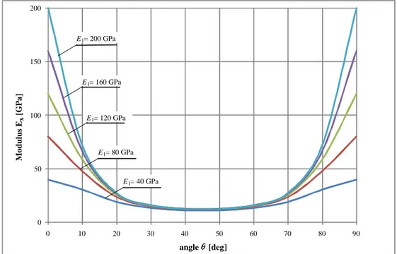
2.3. ENGINEERING MODULI OF ORTHOTROPIC MATERIALS 97
2.4. COORDINATE TRANSFORMATIONS 100
2.5. PLANE-STRESS CONDITIONS 105
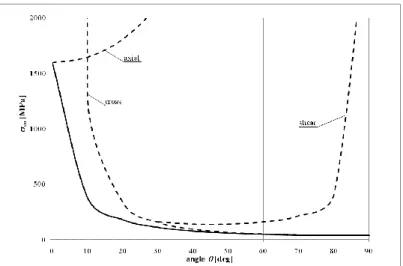
2.6. FAILURE CRITERIA 113
2.7. MICROMECHANICAL CHARACTERIZATION OF A UNIDIRECTIONAL LAMINA 116
2.8. HYGROTHERMAL EFFECTS 118
CHAPTER 3 – ON THE AXIAL BEHAVIOR OF WEB-FLANGE JUNCTIONS OF PFRP I-PROFILES 121
3. INTRODUCTION 121
3.2.2. SECOND GROUP: INFLUENCE OF THE LOCATION OF PULL-OUT
LOAD ON JUNCTIONS’ STIFFNESS & STRENGTH 172
3.3. FINITE ELEMENT ANALYSIS 186
3.4. RESULTS OF THE FIRST PHASE OF THE RESEARCH 198
CHAPTER 4 – ON THE AXIAL AND ROTATIONAL BEHAVIOR OF WEB-FLANGE JUNCTIONS OF PFRP H- AND L-PROFILES 201
4. INTRODUCTION 201
4.1. EXPERIMENTAL INVESTIGATION (@UCI) 203
4.1.1. PULL-OUT TEST SETUP AND INSTRUMENTATION 203
4.1.2. RELATIVE ROTATION TEST SETUP AND INSTRUMENTATION 209
4.2 EXPERIMENTAL RESULTS 213
4.2.1. PULL-OUT TEST RESULTS 213
4.2.1.1. GROUP 1: MİD-POİNT LOADİNG TESTS RESULTS 217
4.2.1.2.GROUP 2: ECCENTRİC-POİNT LOADİNG TESTS RESULT 224 4.2.2. RELATIVE ROTATION TEST RESULTS 230
4.3 FINITE ELEMENT ANALYSIS 245
4.4 RESULTS 259
CHAPTER 5 – CONCLUSIONS 263
5. INTRODUCTION 263
5.1. EXPERIMENTAL RESULTS (@UNISA) 264
is not enough.
Special thanks to my academic advisor and mentor, Professor Luciano Feo. His encouragement, guidance, and feedback throughout this process were invaluable. Whether it was a page or two of hand-written notes or a quick email pushing me forward, his words were always well-timed and inspiring. I look forward to collaborating with him on future research projects.
I would also like to express my gratitude to Professors Ayman S. Mosallam and Francesco Ascione whose advices, challenging questions and support during this investigation were instrumental to its success. I would welcome the opportunity to work with each of them again.
materials whose use has spread from the aeronautical, mechanical and naval industry to civil infrastructure, which has generated a new set of challenges. Composites have unique features, such as high corrosion resistance, electromagnetic transparency, low maintenance costs and high strength-to-weight ratio. During the past few decades, pultruded fibre-reinforced polymer (PFRP) composites have been used in several successful applications related to corrosive environments such as cooling towers, mining and petrochemical facilities, water and wastewater treatment plants, as well as, off-shore structures. By mid-1990s, major applications of these materials were initiated in the field of seismic and corrosion repair and strengthening of existing reinforced concrete bridges and buildings.
Historically, off-the-shelf PFRP composites were developed and designed by the pultrusion industry and were intended for low-stress applications. Recently, composites have been introduced as primary structural members to replace or complement other conventional materials, such as steel, concrete and wood, in critical applications such as bridge decks, pedestrian bridges, and recently in highway bridges and other infrastructural systems [1, 2].
structural steel members (e.g. I-, H-, C- and angles profiles); however, these steel-like profiles do not represent the optimum geometry for PFRP composites.
Unlike isotropic, time-independent structural materials, all PFRP pultruded materials are anisotropic and are characterized as viscoelastic materials [3-5]. Their stiffness and strength have values that depend on the orientation of the fibres. Consequently, these materials, under ambient environments, behave differently from those isotropic time-independent structural materials such as steel, under service, ultimate loads and dynamic excitations.
In order to ensure the structural reliability of load bearing pultruded composite members, the shape and fibre architecture of PFRP profiles must be optimized and designed properly.
Standard engineering guidelines, analytical and design tools developed for conventional materials are not applicable to FRP shapes. For this reason, several technical documents dealing with design equations and methods, material properties and safety factors for pultruded elements have been or being developed in recent years.
In particular, the EuroComp Design Code and Handbook [6], published in 1996, provided, for the first time, an independent, practical guidance on structural design of polymer composites.
In 2007, the Italian National Research Council (CNR) published the first Italian design guide (DT 205/2007) for the design and construction of structures made of FRP pultruded elements [8] which is not a binding regulations and is still rather incomplete.
Finally, in 2011, the Construction Institute of the American Society of Civil Engineers (ASCE) published the Manuals of Practice (MOP) #102 for the design of FRP composite connections [9]. This manual covers major issues related to the analysis and design of composite joints and frame connections manufactured from fibre-reinforced polymer composites in general and pultruded composites in particular. Currently, a joint effort between the Pultrusion Industry Council (PIC) and the ASCE Structure Institute for developing American Standards for PFRP structures is underway and will be published in the near future.
On the other hand, numerical simulation techniques such as finite element analysis (FEA), which could provide a more reliable prediction of the behavior of composite structures, may be difficult to use for typical office engineer, since these require specialized training. Therefore, in order to safely expand the use of pultruded composites in more structural applications, a comprehensive design protocol should be developed and should be accessible to practitioners in order to increase
their confidence level in such relatively new materials. At the same time, it became critical and essential to understand their short- and long-term mechanical behavior, as well as the behavior of their connections.
In recent years, relevant studies have been conducted and focused on the performance of PFRP frame structures and several research programs on optimizing pultruded composites have been initiated. For example Davalos et al. [10] presented an approach for flexural analysis and design of pultruded beams. This approach involved computational procedures for utilizing fibre volume fraction of the constituents, ply stiffness and panel laminate engineering constants. Over the past two decades or so, a number of studies focusing on the performance of PFRP connections and frame structures have also been reported. Some of the pioneering studies on PFRP frame structures were reported by Mosallam et al. [11-15] presenting the results of a comprehensive theoretical and experimental program to evaluate both the short-and long-term behavior of PFRP structures subjected to both quasi-static and sustained loading.
A highly complex and delicate mechanical aspect unique to steel-like unidirectional PFRP profiles is associated with the strength and stiffness of web-flange junctions (WFJ) of such profiles due to the insufficient fibre continuity.
In fact, the junction of web and flange of PFRP profile is an area that is relatively rich in resin and poor in fibers (matrix-dominated).
Some relevant studies related to this topic have highlighted the influence of the architecture of the web-flange junctions on the premature collapse of PFRP profiles. In fact, the mechanical properties of the WFJ are not the same as those of the web and the flanges due to the fact that this portion of the profile is resin-rich as compared to the web and flanges fibre-rich characteristics. Consequently, creep behavior of such zones may lead to a time-dependent failure. For example, Turvey and Zhang [20-22] have conducted an experimental investigation on web-flange junctions of 203 mm × 203 mm × 9.5 mm PFRP beams. Their study included junctions shear strength, rotational strength and stiffness, as well as the mechanism of tearing failure. The results of the study concluded that the collapse of the PFRP beams is a function of combined high shear stresses as well as bending stresses at the interfaces of different plies. Borowicz and Bank [23] have developed a design equation that governs the behavior of pultruded FRP beams subjected to concentrated loads in the plane of the web. The study also investigated the impacts of bearing plates on the ultimate capacity of these beams, and verifying experimental results through finite-element modeling.
This dissertation has been developed within the research activities of a multi-phase comprehensive joint research program between University of Salerno, Italy,
and the University of California, Irvine, USA, on investigating one of the major structural issues that defines the strength limit-state of pultruded fibre-reinforced polymer profiles. Specifically, the axial and rotational strength and stiffness of the web-flange junction (WFJ) of the majority of commercially-produced pultruded composite profiles.
As seen from the literature review, the failure mechanism of pultruded profiles web-flange junctions has yet to be fully understood and they often involve failure of the web-flange junctions. However, the local failure may have different modes due to the variability of materials properties of pultruded composites.
With this aim, the research activities have been developed in the following 4 phases:
- the first phase has been dedicated to the study of the mechanics of composites materials and their failure criteria (Chapter 2);
- the second phase consisted of an experimental investigation carried out at the Materials and Structural Testing Laboratory (LMS) of the Department of Civil Engineering (DICIV) of the University of Salerno in order to evaluate the axial strength and stiffness of WFJ of PFRP I-profiles [24-31] (Chapter 3);
- the third phase was an experimental study conducted at the Structural Engineering Testing Hall (SETH) of the University of California Irvine (UCI) to evaluate both the axial and the rotational strength and stiffnesses of WFJ of PFRP H- and L-profiles. From the results of the experimental investigations developed in
- the last phase consisted of a finite element analysis (FEA) and a comparison of the numerical results with the experimental findings (Chapter 5).
References of the Summary
[1] Mosallam A. S., Chapter on composites in construction. Materials selection handbook. John Wiley Publishing Co; 2002 [chapter 45].
[2] Bank L. C., Composites for construction: Structural Design with FRP Materials. John Wiley & Sons; 2006.
[3] Kollár L. P., Springer G. S., Mechanics of composites structures. Cambridge University Press; 2003.
[4] Ascione L., Feo L., Mechanical behavior of composites for construction. In “Wiley Encyclopedia of Composites”, 2nd Edition, John Wiley & Sons, 2, pp.1625-1649; 2012.
[5] Barbero E. J., Introduction to composite material design. Taylor & Francis, Philadelphia; 1998.
[6] Eurocomp Design Code and Handbook, Structural design of polymer composites. The European Structural Polymeric Composites Group; 1996. (ISBN 0419194509). [7] European Committee for Standardization (CEN). EN 13706: Reinforced plastics
composites – Specifications for pultruded profiles. Part 1: Designation; Part 2: Methods of test and general requirements; Part 3: Specific requirements, Brussels: CEN; 2002.
[8] Technical Document CNR-DT 205/2007. Guide for the design and construction of structures made of FRP pultruded elements. Italian National Research Council (CNR) Rome; 2008.
[9] Mosallam A. S., Design guide for FRP composite connections. Manuals of Practice (MOP) 102. American Society of Civil Engineers (ASCE); 2011. ISBN9780784406120: 624.
[10] Davalos J. F., Salim H. A., Qiao P., Lopez-Andio R., Analysis and design of pultruded FRP shapes under bending. Composites Part B: Engineering, 27B (3,4), pp. 295–305; 1996. [11] Mosallam A. S., Abdelhamid M. K., Conway J. H., Performance of pultruded FRP
connection under static and dynamic loads. Journal of Reinforced Plastic and Composites, 13, pp. 1052–1067; 1996.
[12] Mosallam A. S., Abdelhamid M. K., Dynamic behavior of PFRP structural Sections. In Proc. of ASME (Energy Sources Tech. Conf. and Expo, Composite Material Tech.), 53, pp. 37–44; 1993.
[13] Mosallam A. S., Bank L. C., Short-term behavior of pultruded fiber reinforced plastic frame. Journal of Structural Engineering (ASCE), 118(7), pp. 1037–1954; 1992. [14] Liu X., Mosallam A. S., Kreiner J., A numerical investigation on static behavior of
pultruded composite (PFRP) portal frame structures. In Proceeding of the 43rd International SAMPE Symposium and Exhibition, Anaheim, California; 1998.
[15] Mosallam A. S., Durability of pultruded fiber reinforced polymer (PFRP) composites in mining environments in Durability of fiber reinforced polymer (FRP) composites for construction. Edited by B. Benmokrane and H. Rahman, pp. 649-659; 1998.
[16] Bank L. C., Nadipelli M., Gentry T.R., Local buckling and failure of pultruded fiber-reinforced plastic beams. Journal of Engineering Materials and Techology, 116, pp. 223–237; 1994.
[17] Bank L. C., Yin J., Failure of web-flange junction on postbuckled pultruded I-beams. Journal of Composites for construction, 177, pp.177-184; 1999.
[18] Turvey G. J., Zhang Y., A computational and experimental analysis of the buckling , postbuckling and initial failure of pultruded GRP columns. Composites & Structures, 84, pp 1527-1537; 2006.
[19] J. R. Correia, F. A. Branco, N. M. F. Silva, D. Camotim, N. Silvestre., First-order, buckling and post-buckling behaviour of GFRP pultruded beams. Part 1: Experimental study. Computers and Structures, 89, pp. 2052-2064; 2011.
flange junctions of pultruded GRP WF-sections via web bending tests. Composites Part A: applied science and manufacturing, 37, pp. 152–164; 2006.
[22] Turvey G. J, Zhang Y., Shear failure strength of web-flange junctions in pultruded GRP WF profiles. Construction and Building Materials, 20, pp. 81–89; 2006.
[23] Borowicz D. T., Bank L. C., Behavior of pultruded fiber-reinforced polymer beams subjected to concentrated loads in the plane of the web. Journal of Composites for Construction, 15, pp. 229–238; 2011.
[24] Mosallam A. S., Elsadek A. A., Pul S., Semi-rigid behavior of web-flange junctions of open-web pultruded composites. In Proceeding of the International Conference on FRP Composites, San Francisco, California; 2009.
[25] Feo L., Mosallam A. S., Penna R., Preliminary results of an experimental and computational analysis of the behavior of web-flange junctions of GFRP pultruded profiles subjected to concentrated loads. In Proceeding of the 15th European
Conference on Composites Materials (ECCM15), Venice; 2012.
[26] Feo L., Mosallam A. S., Penna R., An Experimental Investigation on the Behavior of Web-Flange Junctions of GRP Pultruded Profiles in Proceeding of the ICCE–20 (20th
Annual International Conference on Composites/Nano Engineering), Beijing; 2012. [27] Feo L., Penna R., Analisi delle tensioni nei nodi “ala-anima” di profili pultrusi
fibrorinforzati in Proceeding of the Italian Association for Stress Analysis (AIAS) Conference, Padova (Italy); 2012.
[28] Feo L., Penna R., On the behavior of web-flange junctions of GRP pultruded profiles. In Proceedings of Riga Technical University 53rd International Scientific Conference
dedicated to the 150th anniversary and 1st Congress of World Engineers and Riga
Polytechnical Institute / RTU Alumni. Riga (Latvija); 2012.
[29] Elsadek A., Mosallam A., Pul S., Feo L., Penna R., Experimental Evaluation of Axial Flexibility of Web-Flange Junctions of Thin-Walled Pultruded H-Profiles, Composites Structures, In press; 2012.
[30] Feo L., Mosallam A. S., Penna R., Experimental and numerical results on the failure strength of web-flange junctions of thin walled pultruded composites profiles, in Proceeding of the Italian Association for Stress Analysis (AIAS) Conference, Salerno (Italy); 2013.
[31] Feo L., Mosallam A. S., Penna R., Mechanical behavior of web-flange junctions of Thin-walled pultruded I-profiles: An experimental and numerical evaluation. Composites Part B: Engineering, Volume 48, Pages 18-39, May 2013.
[32] Feo L., Mosallam A. S., Elsadek A., Pul S., Penna R., Structural evaluation of axial and rotational flexibility and strength of web-flange junctions of open-web pultruded. Composites Part B. (2014), Volume 66, Pages 311-327, October 2014.
1. INTRODUCTION
Understanding the behavior of frame connections for pultruded fiber reinforced polymer (PFRP) structures is an essential key to satisfying both the safety and efficiency requirement of such structures. This issue is particularly important when designing load-bearing pultruded composite structures such as bridges and
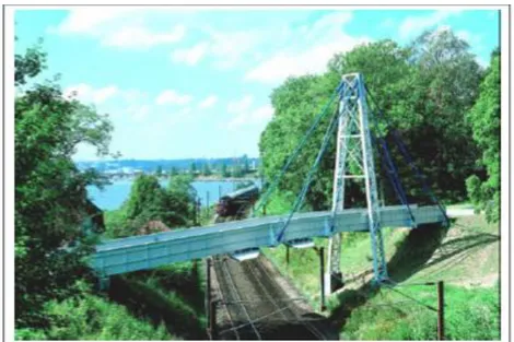
Figure 1.1. The Fiberline All-Pultruded Composites Cable Stayed; Kolding, Denmark.
Figure 1.3. Pultruded composites frame structure.
Despite their critical structural role, little attention has been given to PFRP frame connections. Regardless of the type of material used in any structural system, connections are needed to attach member ends to other structural members sufficiently to allow the loads to continue in an orderly flow to the foundation. The efficient connection design must produce a joint that is safe, economical and practical. For other construction materials such as steel, varieties of structurally sound connection details are available. Until recently, most available connection details were duplications of steel details. For this reason, and due to the absence of an authoritative unified design code, structural designers of most PFRP structures built in the last decade, or so, have utilized - and continue to utilize - the inadequate and in most cases unsafe steel-like connection details (Fig. 1.5).
strong design specifications. Some of the major obstacles limiting the use of pultruded structural composites in the construction industry are the following: - lack of mechanical information on both short and long term performance; - lack of design standards and acceptance by building codes;
- structural deficiency of some structural shapes amplified by a lack of communication and coordination between manufactures and the researches; - limited sponsored-researches programs;
- lack of quality control of commercial products.
In this chapter, the state of the art as well as recommendations for repair and rehabilitation of steel-like PFRP connections are presented and discussed.
1.1. IMPACT OF CONNECTION DETAIL DESIGN ON THE OVERALL BEHAVIOR OF PULTRUDED COMPOSITES FRAME STRUCTURES
The major impact of connection behavior on the overall performance of composite structures includes: (i) buckling and post-buckling capacity, (ii) premature localized-failure of open-web members, and (iii) the ultimate strength as well as the overall creep behavior of thin-walled FRP structures.
In order of pultruded composites to be considered as structural materials for civil engineering applications, these materials must be proven to have structural reliability and higher efficiency under different loading conditions (e.g., dead, live, wind, earthquake, etc.) during the expected useful-life of the structure.
The efficiency of a composite connection can be expressed as: ,
where:
Load producing failure to connection; Load producing failure to member.
For this reason, reliable information on the behavior of pultruded composites under these loading regimes must be available to the structural engineers.
Several research studies have focused mainly on the static behavior of these FRP connections with little work on the dynamic and seismic behavior of these joints. Furthermore, due to the fact that composites are viscoelastic materials, structural engineers must include the long-term (creep) effects under ambient and other varying environmental conditions.
Other studies have been conducted in the area of characterizing the structural behavior of pultruded composite connections. The following is a summary of major studies in this area.
1990 [1]. In this study, detailed theoretical and experimental investigations on the short and long-term behavior of PFRP frame structures were conducted.
In particular, two portal frame structures were constructed from off-the-shelf commercially produced pultruded sections and an analytical investigation was performed to predict their nonlinear response. The numerical model includes the effects of axial, shear and flexural deformation of the pultruded numbers; flexibility of the beam-to-column connections; and the post buckling of the frame girder. An expression for the nonlinear rotational stiffness of the pultruded beam-to-column connection was presented. The experimental data obtained from the full-size test [Fig. 1.6] correlated very well with the analytical model.
In 1992, Bank & Mosallam [2] presented results of an experimental and analytical investigation on the behavior of a pultruded composite portal frame subjected to short-term static loads.
Figure 1.6. Study on PFRP portal frame with steel-like connection details.
The composite profiles used in this study were standard off-the-shelf H-profiles 8”×8”×3/8” (203.2 mm × 203.2 mm × 9.5 mm) glass/vinylester Pultex 1625 pultruded profiles (manufactured by Creative Pultrusions, U.S.A.).
These commercially produced pultruded composite sections consisted of E-glass roving and continuous strand mat (occupying approximately 45% by volume) in a vinylester resin. The beam-to-column and base-plate connections were detailed according to general recommendations of the majority of pultruders’ design manuals [3-6].
of bolts of the top angle, creating a hollow internal cavity in the pultruded section at the flange-web intersection (Figs. 1.7 -1.8).
Figure 1.7. Premature failure of open-web unidirectional pultruded profiles and
Figure 1.8. Premature failure of open-web unidirectional pultruded profiles [Mosallam 1990].
This transverse tension failure occurred perpendicular to the direction of longitudinal fiber reinforced in the pultruded section. The unidirectional pultruded equal-leg angles used in this test program had the major fiber reinforcements running in the wrong directions relative to the load path and applied stresses. For this reason, a premature failure initiated by hair cracks at the corners was unavoidable (Fig. 1.9).
Figure 1.9. Dramatic loss of connection stiffness initiated by the development of hair
cracks at the corners of the pfrp unidirectional angles.
Based on the findings of the experimental study conducted by Bank and Mosallam in 1990, the effect of connection details made of pultruded FRP composites, and their semi-rigid behavior, have been investigated by Bank, Mosallam and Gonsior in 1990 [7]. Figure 1.10 presents the four connection details evaluated in this study.
Figure 1.10. PFRP connection details evaluated.
This pilot investigation involved both experimental and analytical evaluation of several connection details for pultruded frame structures. All of the connections tested focused on exterior beam-to-column joints with flange attachment configuration.
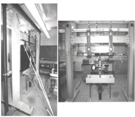
Experimental results of three different PFRP connection details were presented. The test setup used in this study is shown in Figure 1.11.
Figure 1.11. Exterior PFRP beam-to-column connection [Bank, Mosallam and Gonsior (1990)].
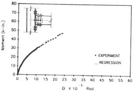
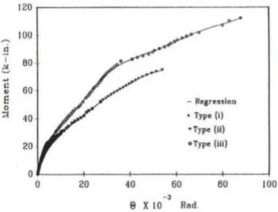
Figure 1.12 shows the typical moment-rotation (M-θ) curve for detail (d) of Figure 1.12, which was the same detail used in the PFRP portal frame investigated by
Figure 1.12 Moment-rotation curve for exterior PFRP beam-to-column connection detail
(d) described in figure 1.10 - Type i.
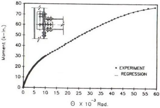
As reported by Bank & Mosallam [1,2], and illustrated in Figure 1.8, a premature failure in the form of a local separation of the column flange from the web was the major cause of the limited strength of this detail. For this reason, Bank, Mosallam and Gonsior [7] suggested a simple detail to avoid this premature failure by introducing a transfer member in the form of a unidirectional pultruded angle placed at the web/flange junction of the column at the connection zone as shown in Figure 1.13. As expected, the addition of this transfer member prevented, to a large extent, the formation of the cavity behind the connection and resulted in an increase in the strength up to 50%. In addition, the plastic relative rotation
full regression analysis was performed.
Figure 1.13. Moment-rotation curve for exterior PFRP beam-to-column connection detail
(d) with transfer angle Type ii [Bank, Mosallam and Gonsior 1990].
Figures 1.14 and 1.15 show the ultimate failure mode of connection details Type i and Type ii, respectively.
Figure 1.14. Ultimate failure mode of connection details Type i.
connection detail, referred to as Type iii, was similar to the Type ii detail, except for replacing the top pultruded angle by a miter connector consisting of two 228.6 mm long, 152.4 mm wide T- Flange elements bolted to the flanges of both the column and beam using 12.7 mm pultruded plates. The fiber orientation of the pultruded plate was aligned at a 45° with respect to the beam and column flanges as shown in Figure 1.16.
Figure 1.16. PFRP connection details Type iii.
The PFRP plate was attached to the slotted section using PFRP threaded rods and FRP molded nuts.
The failure mode of Type iii connection specimen was initiated by a local transverse tension failure of the unidirectional pultruded elements. The initial failure occurred due to the development of high transverse tensile stresses at the unstiffened beam portion beneath the top T-flange miter joint. The second local damage was also caused by the high transverse tension stresses at the slotted section of the flange. This local failure was initiated first through the bolt holes connecting the T-flange and propagated to about half of the pultruded plate. The ultimate global failure was a combination of sudden splitting of the T-flange, shaving of the PFRP threads of the threaded rod connecting the shear PFRP angle, and a separation of the pultruded beam from the column [Fig. 1.17].
detail. However, this graph shows an appreciable increase in both the stiffness and the strength of the Type iii connection detail. The gain in the rotational stiffness of this detail was about 48% as compared to the rotational stiffness of connections
Type i and Type ii. In addition, an appreciable strength gain of about 119%, and
50% was achieved, as compared to ultimate moment capacity of connections Type i and Type ii, respectively.
Figure 1.18. Moment-Rotation Curves of Connection Details Tested by Bank and Mosallam 1991.
In 1992, Bank, Mosallam and McCoy [11] presented a summary of different PFRP frame connections tested in previous studies conducted by Bank and Mosallam [1, 2] and Bank, Mosallam and Gonsior [7]. In addition, a new connection detail was proposed and was referred to as Type iv. Figure 1.19 shows the details connection
Type iv. As seen in Figure 1.19, this connection detail was an improved version of
the connection detail Type iii. However, in this detail, both the top and bottom PFRP seated angles were replaced with the T-Flange/Plate system described earlier for detail Type iii. The PFRP plate was attached to the slotted section using epoxy adhesives and no bolts were used.
Figure 1.19. PFRP Connection Details Type iv.
The ultimate failure of this connection was catastrophic due to failure of the adhesives (Fig. 1.20). The adhesive failure was attributed to lack of sufficient
connection details (Types i, ii, iii, and iv). As shown in this figure, a substantial improvement in both the strength and rotational stiffness was achieved using this connection detail. For example, the gains in the strength and rotational stiffness were about 196% and 272%, respectively, as compared to the strength and stiffness of connection detail Type i used in the portal frame study by Bank and
Mosallam in 1990 [1].
Figure 1.20. Adhesive failure of connection detail Type iv.
Type iv is 0.02 rad vs. ultimate relative rotation of Type iii of 0.09 rad). This results
reflected the lack of ductility of connection detail Type iv.
Figure 1.21. Moment-rotation curves of four connections details [Bank, Mosallam and McCoy (1992)].
pultruded products as connecting elements (e.g. Bank & Mosallam in 1990 [1], Bank &
Mosallam in 1991 [8-10]), a different approach was adopted by Mosallam in 1993
[12] and Mosallam et al. [13] to develop customized connection details. In fact, in 1993
Mosallam [12] presented a novel approach to connecting PFRP framing elements using
appropriate composite connectors. As said, the development of these connectors was the result of a combination of past experience, available research and design data, and knowledge of the anisotropic behavior of the composite materials.
The design criteria for what is called the Universal Connector (UC) included: - proper fiber orientation;
- ease of erection and duplication;
- geometrical flexibility and suitability for use in connecting a large variety of
commercially available pultruded shapes;
- maximizing both the overall connection stiffness and ultimate capacity.
The first UC prototype was modified and optimized using finite element (FE) techniques by Mosallam et al. in 1994 [13]. Figure 1.22 shows the dimensions and the geometry of the modified version of the UC connector. The FRP connector prototype was designed and fabricated from E-glass/vinylester composition.
Figure 1.22. Dimensions and geometry of the modified Universal Connector (UC).
The UC element was made in order to be used for the majority of PFRP connections for different shapes, e.g., exterior and interior beam-to-column connections, column-base connections, continuous beam connections, beam-to-girder connections, and others. In order to verify the performance of this engineered composite connector, a comprehensive experimental program to evaluate quasi-static, dynamic, creep and low fatigue cyclic behavior of connections constructed using the UC element(s) was conducted by Mosallam et al. between 1993-1999 [13-23].
This experimental program was composed of the following phases: i) quasi-static behavior of UC connections;
ii) cyclic behavior of exterior UC PFRP connections;
iii) UC PFRP connection response under sustained loads (creep test); iv) vibration and damping evaluation of UC PFRP frame connections; v) evaluation of mechanically fastened UC exterior flexible connections;
All beams and columns (Fig. 1.23) were constructed from "off-the-shelf" (101.6 mm × 101.6 mm × 6.35 mm) PFRP E- glass/vinylester H-profile manufactured by Bedford Reinforced Plastics Company (USA) [3]. The connecting elements used for these joints were, namely, a combination of the following: high-strength epoxy adhesive pultruded threaded rods and nuts, UC # 4, PFRP (76.2 mm × 76.2 mm × 9.53 mm), equal-leg unidirectional angles.
The objective of testing these connection details were to:
i) determine, experimentally, both the rotational stiffness and the ultimate strength of each connection detail;
ii) evaluate the performance of the newly designed and developed prototype of the universal connector;
iii) identify the different failure mechanisms of each connection;
iv) investigate the impact of using high-strength adhesive in both the strength and the stiffness of beam-to-column connections.
In order to characterize the rotational stiffness of PFRP connections, two measurements were obtained from the test. The first quantity was the applied moment at the connection, and the second quantity was the relative angle of rotation between the beam and the column. Details of these calculations can be found in Bank, Mosallam and
Figure 1.23. Typical geometry, dimensions and details of the PFRP exterior frame connection
specimens.
Figure 1.24 shows details of the PFRP beam-to-column connection tested in this program. The same connection designation system used in 1992 by Bank, Mosallam and
McCoy [11] was adopted by Mosallam et al. in 1993 [12] to assist the reader in relating
and comparing the behavior of each connection and to add continuity to the research subject. Accordingly, the three PFRP connections developed in this study were designated as: Types v, vi, and vii. The design of the these three connections included PFRP threaded rod stiffeners.
Figure 1.24. Details of the PFRP exterior frame connection: Types v, vi and vii.
As discussed earlier, the addition of these threaded rod stiffeners can be recommended in order to prevent the premature separation of the web and flanges of the PFRP H-sections (this recommendation applies to all open-web PFRP unidirectional profiles). Furthermore, this stiffening technique can ensure the integrity of the three composite plates (the flanges and the web) forming the H-shape. Consequently, an efficient utilization of the PFRP sections can be achieved by both enhancing the stiffness characteristics and increasing the ultimate strength of the connection. Based on past
experience, this stiffening detail could be strongly recommended at any high tensile stress concentration zones of PFRP open-web thin-walled structural shapes (e.g., H, I,). The locations of high stress concentration are likely found near the connections (maximum shear and maximum negative moments), near the girder mid-span (maximum positive moments) and at the locations of concentrated loads (maximum shear). The need for this stiffening detail is especially important when minimum fiber reinforcement at the web-flange junction (WFJ) is provided. Unlike connection details (vi) and (vii), no UC element was employed in connection detail Type v. Instead, two PFRP unidirectional angles 3" × 3" × 3/8" (76.2 mm × 76.2 mm × 9.53 mm) were placed at both the top and the bottom of the beam. The connection was stiffened by PFRP threaded rods and FRP molded nuts. To investigate the effect of using adhesive in the overall performance of the joint, connection detail Type vii was designed.
This connection has the same details as connection Type vi except for the addition of thin films of high-strength epoxy adhesive (Magnobond 56 supplied by Bedford Reinforced Plastics, U.S.A.) between the contacting surfaces between the UC’s and both the beam and the column. The experimental moment-rotation (M-θ) curves of the three connection details are shown in Figure 1.25. A linearized version of these curves is shown in Figure 1.26.
Figure 1.25. Experimental Moment-Rotation Curves for the Three PFRP Frame Connections:
Types (v), (vi) and (vii).
Figure 1.26. Linearized moment-rotation curves for the three PFRP frame connections: Types v, vi and vii.
Careful analysis of the three moment rotation curves shown in Figure 1.26 reveals the following facts: 1) the behavior of the three connections was "near-linear" up to about 80% of the ultimate moment capacity; 2) a premature failure of connection Type v was due to the duplicating metallic connection detail; 3) the use of the universal connector improved greatly both the overall stiffness and the ultimate flexural strength of the two
UC connections (Types vi and vii); 4) a complete fixity was achieved in the initial
loading history of connection Type vii by using a combination of bolts and high-strength epoxy adhesive
In addition, the following experimental information is important for the structural engineer in the design and the selection process of PFRP frame connection details including: a) the ultimate capacity of the connection; b) the service and the ultimate deformation of the connection. This rotational information can be obtained using both the average rotational stiffness (Ka) and the ultimate angle of rotation (θu). For moderate loading conditions, an initial rotational stiffness (ki) can be used (Gerstle [24],
Bank & Mosallam [1]).
1.2.2.2. Evaluation of Mechanically Fastened UC Exterior Flexible Connections
As an extension of this program, a new flexible “seated” detail of a beam-to-column connection was evaluated in 1993 by Zahr et al. [25]. Details and test setup of this connection are shown in Figures 1.27 and 1.28, respectively.
Figure 1.27. Details of the PFRP flexible connection (Type viii).
The connection was tested under quasi-static loading regime. The failure was due to the large deformation on top side (tension) of the connection. As expected, and due to the flexible nature of this connection detail, as the load increased, a large horizontal relative rotation between the beam and the column flange was observed (acting as a hinged
support as intended). The ultimate failure of the connection was due to a local failure of
the web/flange junction at the top of the open-web H beam (high tensile stress concentration). This mode failure provides additional evidence of the importance of using reinforcing details such as threaded rod/nut system (Mosallam [14]) or transfer members such as angles at the junction with high stress concentration (Bank and
Mosallam [8-10]). Figures 1.29 and 1.30 present the experimental and bi-linear
representation of the moment-rotation behavior of this flexible detail.
Figure 1.30. Bi-Linear representation of the experimental moment-rotation curve for UC
PFRP flexible frame connection.
Comparing the stiffness and strength information presented with the results of connection details Types vi and vii, it can be seen the great difference in behavior. For example, the initial stiffness of this flexible detail is about 39% of the corresponding stiffness of connection Type vi, and about 1.2% of the initial stiffness of connection
Type vii (fixed vs. hinged). This type of connection has negligible moment capacity of
0.45 kip-in (0.051 kNm) as compared to 20.50 kip-in (2.31 kNm) and 28 kip-in (3.36 kNm) of connections Types vi and vii discussed earlier. For this reason, this detail is the recommended shear type connection.
1.2.2.3. Quasi-Static and Cyclic Behavior of Interior PFRP Frame Connections
In 1999, a comprehensive program to evaluate the structural performance of different types of interior PFRP frame connections was conducted by Mosallam [23]. In this study, several full- scale cyclic tests were conducted on several pultruded-framing elements. This included box and H-beam profiles with different sizes. The emphasis of this study was on interior framing connections with both flange and web attachments. In addition to high-strength adhesives, both FRP and steel mechanical fasteners were studied. Bolted-only, adhesively-bonded-only and combined-joint details were evaluated using both metallic and non-metallic bolts. Strain, deflection, and load information were collected using a computerized data acquisition system. In particular,
M-θ and P-δ hysteresis curves were developed and analyzed. For FRP mechanical
fastener bolted-only connections, a common mode of failure was observed for all specimens. This was a combination of bolt thread shaving and flexural fatigue-type failure of pultruded threaded rods. Other local failures of the pultruded thin-walled beam sections were observed at the ultimate moment. Delamination cohesive failures were also observed for adhesively bonded connection details.
The connecting elements used in building the connection specimens included unidirectional pultruded angles, Universal Connectors (UC) and Continuous Universal
Connector (CUC) as shown Figure 1.31.
Figures 1.32 and 1.33 show the typical test setup for interior and exterior connections, respectively.
Figure 1.31. Continuous Universal Connector (CUC).
Figure 1.32. Test Setup for Interior Connections.
1.2.3. Mottram et al. (1994-1999)
In 1994, Bass and Mottram [26] presented experimental results of five steel-like flange-cleated sub-assemblies. Commercially produced pultruded profiles, similar to those tested by Bank et al., were used. Figure 1.34 shows the different details tested in this program. Of the five full-scale interior connection tests, three major-axis (i.e., the beam connected to the column flanges) H-profile connection details were tested. Both steel mechanical fasteners and adhesives were used in building these connections.
In 1996, Mottram and Zheng [27] presented a comprehensive state-of-the-art review on connection design for pultruded structures. In this review, the researchers divided the test program into two connection groups similar to the classification adopted by the steel industry (AISC-LRFD). These two groups are: Type I - Pinned Connections and
Type II - Semi-rigid Connections.
- Type I (Pinned) connection details: three types of connecting regimes were tested; namely, i) bolted- only, ii) bonded-only, and iii) combined bolted/bonded connection detail. All connection details were similar to those recommended by the Strongwell Design Manual [5] as shown in Figure 1.35.
Figure 1.35. Pre-1995 Strongwell Design Manual Connection Details Tested by Mottram &
Zheng.
In general, the major function of these connections was to transmit the shear forces from beams to column. However, and as indicated from the experimental results, pinned connections had a limited capability to transmit bending moments to the column. A sudden adhesive failure was observed for bonded-only connection details at a relatively low load level.
Based on the experimental results, Mottram & Zheng 1996 [27] recommended avoiding the use of adhesives as the sole connecting media. It was also concluded that when beams are connected to the column web (minor axis attachment), relative rotation would decrease due to the elimination of the deformation resulting from the prying action
Zheng in 1996 was classified as Type II or “semi- rigid" connection details. A total
of five full-scale connection specimens were tested. Both adhesives and metallic mechanical fasteners were used. In particular, the authors used double unidirectional cleat angles (Figure 1.36) to increase the flexural strength of these connections.
Figure 1.36. Mottram Double Cleat Angle Details.
Again, the fibers in both angles were running in the wrong direction, and the only addition was the increase of the matrix cross-section by doubling the thickness of the cleat angles (in their case Isophthalic polyester). For the same reason, the same expected delamination failure of the top cleat occurred. This common type of failure for steel-like connections was described in detail by Mosallam [14]. The same stiffening approach
was adopted by Sanders et al. [28] in their experimental study on the behavior of adhesively bonded "steel-like" pultruded connections.
As compared to other composite/composite connection details, this type of connection exhibited a relatively lower strength and rotational stiffness up to failure. The first observed localized failure was due to flexural rupture of the beam's top flange at the location of the single row of steel bolts. There are several disadvantages of using this hybrid connection detail (metallic/composite), including:
- limitation of usage in a corrosion or electromagnetic environments;
- mechanical properties mismatch (both short- and long-term) between steel and composites;
- thermo-mechanical properties mismatch including the coefficient of thermal expansions of metallic and non-metallic connection components.
Mottram & Zheng, in 1996, tested two other "steel-like" connection details [27]. The
first connection detail was identical to that presented and tested by Mosallam et al. [12-15].
In this detail, in order to avoid the inherent premature local failure of the column section at the connection zone, these researchers adopted the recommendations given by
Mosallam in the above mentioned studies concerning the use of prestressing double-nut
threaded rods connecting the two flanges of the column at the connection zone.
In an effort to increase the rotational stiffness of the connections and to overcome the premature failure of the connecting elements, Mottram & Zheng [1996] used steel
Figure 1.37. a) Steel/Composite Detail; b) Semi-rigid Composite Detail.
Based on this study, the authors reached the following conclusions:
(i) define standard definitions and design parameters for connection design of pultruded
composite structures;
(ii) develop standard test methods to determine connection properties under both short-
and long-term loading conditions;
(iii) consider new connection pieces and/or connection details, such as the UC
developed by Mosallam that will ensure a connection with adequate strength and stiffness for primary pultruded load-bearing frame structures.
1.2.4. Smith et al. (1996-1999)
In 1996, Smith et al. [29] presented a study on the behavior of exterior beam-to-column connections using both pultruded rectangular tubes and I-profiles. The study focused on the static behavior of two full-scale connection details. The testing protocol followed that adopted by Mosallam in 1990 as shown in Figure 1.39. The two pultruded cross sections used in building the full-scale connection specimens are shown in Figure 1.40.
Figure 1.39. Smith et al. Test Setup (1996).
1.2.4.1. I-Beam: Standard Connection Detail
Two connection specimens were fabricated and tested. The failure modes of the two specimens were similar. The failure was initiated at the column face of the clip angles as the outer surfacing veil delaminated from the uniaxial reinforcement region. Immediately following this local failure, the unidirectional top angle failed resulting in collapse of the frame.
1.2.4.2. I-Beam: Thick Seats Connection Detail
This detail was similar to the standard connection detail reported earlier. The result of the first test indicated that the bottom seat pultruded angle contributed the overall stiffness of the connection. For this reason, a thicker pultruded angle was used in this detail. Again, the reader should be aware of the fact that the fibers are still running in the wrong direction and that the stiffness increase was gained by increasing the thickness of “unreinforced” plastic section. A slight increase in the ultimate moment capacity of the connection was also reported. However, this detail did not solve the problem associated with premature failure of the open web pultruded sections of both the column and the beam element due to the lack of adequate fiber continuity between the flanges and web elements of the commercially-produced I-profile as mentioned earlier. For this reason, extensive cracking along the column web-flange interface was observed. It should be noted that there was a direct relationship between the overall stiffness of the connection
Figure 1.41. I-Beam: Thick Seats Connection Failure [Smith et al. (1999)].
It really does not matter how stiff the connecting element is as long as the individual members exhibit flexible behavior whether due to inherent low modulus or to faulty member fiber architecture design (as in the case of unidirectional (90o) pultruded angle connectors used in this detail). This will be
clearly proven by observing the behavior of the next connection detail, where steel angles with higher stiffness were used. In addition, it should be noted that only a single connection test was conducted.
1.2.4.3. I-Beam: Steel Connection Detail
In this test, two connection details were tested. The sections of both column and beam were pultruded I-profiles. The beam was connected to the column by two mild steel angles. As expected, the overall stiffness of the connection was increased due to the higher stiffness of the steel angles.
The ultimate moment capacity was also increased. The failure was in the form of separation of the column inner flange from the adjacent web interface. This failure mode should be avoided. In joint design for other materials such as steel and concrete, designers follow a concept called the “weak beam/strong column” concept. The idea is to ensure the occurrence of the ultimate failure away from the column and the joint region. Preventing this type of column failure, as reported in several papers by Mosallam, can be accomplished by introducing a prestressing threaded rod elements to avoid the inherent premature failure of web/flange junctions of the commercially produced open-web pultruded sections. Another important problem associated with this steel/composite hybrid connection was the mechanical and thermal properties mismatch (Esteel = 29 × 106 psi vs. EFRP = 2 to
3 × 10⁶ psi). This can result in both short- and long-term serviceability and
FRP box beam. Two connection specimens were tested in this program. A combination of adhesives and steel bolts was used. In addition, two side plate elements were attached to the sides of both beam and column as shown in Figure 1.42. The plates were commercially produced unidirectional plates with ¼” (6.35mm) thickness. Failure of this detail was sudden with no warning. The failure was initiated by a brittle fracture of one of the side plates at the bolt hole closest to the facing flange. This failure was propagated along the entire plate resulting in a complete failure of one of the side plates and then of the top unidirectional pultruded angle as shown in Figure 1.42.
Figure 1.42. Standard Box Connection Detail [Smith et al. 1996, 1999].
The failure mode of the second specimen occurred at the beam side wall. The side wall separated completely from the rest of the beam member leading to immediate failure of the pultruded angle. The authors attributed this type of failure to a combination of a relatively thin side wall thickness of the tubular profile as well as to the inadequacy of the uniaxial reinforcement at this region.
1.2.4.5. Box: Gusset Connection Detail
The detail of this connection is shown in Figure 1.43. In addition to the two top and bottom unidirectional angles, two side pultruded gusset plates were added. The plates were bolted via steel bolts to the sides of the box beam and column sections. The gusset plates were aligned so that the fibers are running at 45o relative to both
moment capacity of the connection was increased. The mode of failure was similar to the standard connections initiated by a tensile failure of the sides of the beam box section at the top of the beam side as shown in Figure 1.44. The longitudinal cracks propagated along the length of the beam section. This local failure was expected due to the unidirectional nature of the pultruded box beam and the mechanical property mismatch of the steel bolts and the pultruded composite materials. When compared to all other connection details tested by Smith et al. in 1999 [30], this connection detail achieved the highest opening stiffness of 3,100 kN-m/rad. The ultimate moment capacity was 5.80 kNm.
Figure 1.43. Details of the Gusset Connection Detail [Smith et al. 1999].
to be fabricated as a single monolithic unit fully utilizing the entire column section. The primary fabrication difficulty of bolting closed section connections would be resolved by using the boltless nature of the proposed cuff connector. Ideally, using this connector, the beam and column can fit into the hollow section and then be bonded using epoxy adhesives without the need of mechanical fasteners. However, no prototype for this connection was reported by Smith et al. [30].
Figure 1.46 shows the closest attempt to the proposed cuff design. A built-up cuff section was constructed by using four unidirectional pultruded angles. One leg of these angles was cut and cut portions were attached to the column side wall by means of two steel bolts at each side of the column. At the beam section, the complete two-leg angles wrapped the outer box beam side and top flange as shown in Figure 1.47. The legs attached to the top and the bottom flanges of the box section were connected to the column inner flange via bolted pultruded angles. The specimen was subjected to a quasistatic loading regime until failure. The opening stiffness of this connection was about 42% of the corresponding stiffness of the FRP gusset connection detail described earlier. However, this detail achieved the highest ultimate moment capacity among all connection details tested in this program with an ultimate value of 6.2 kNm (54.87 kip-in). The ultimate mode of failure was in the form of web-flange junction separation of the upper portion of the pultruded box column as shown in (Figure 1.47). As shown in this figure, one side wall separated from the facing flange and the other side wall also separated from the back flange. This typical mode of failure was reported earlier for open-web pultruded profiles such as H-sections due to the lack of fiber continuity between the webs and flanges (Mosallam, 1994). As discussed earlier, this premature failure could have been avoided by using Mosallam's recommendations for using a threaded rod prestressing rod extended through the box section at the connection zone.
Figure 1.46. Details of Built-Up Cuff Connection [Smith et al. (1999)].
Figure 1.47. Ultimate Failure mode due to web/flange separation at the column section [Smith et al. (1999)].
1.2.4.7. Box: Steel Connection Detail
This hybrid connection detail is identical to the standard box section details except that the PFRP plate was replaced with steel plate as shown in Figure 1.48. While the highest opening stiffness was achieved by the FRP guest detail, this connection detail achieved the highest closing stiffness of 1.300 kN m/rad. However, for some reason, no value was reported for the opening stiffness of this connection detail, which is expected to be relatively higher as compared to other details due to the major increase in the stiffness resulted from the use of the steel plate. The failure mode was a combination of both localized beam failure and web/flange junction separation of the column-facing flange. Due to these premature local failures of the unidirectional pultruded composite profiles, the ultimate moment capacity was slightly lower than the ultimate moment value achieved by FRP plate detail. Based on the poor performance of this hybrid detail, it was concluded that, regardless of the added capacity of the individual connection elements, this detail did not succeed in overcoming the weakness of the local failure of the commercially produced unidirectional pultruded profiles. Unless the load path is modified or load is redistributed, the steel detail will have a limited strength contribution. However, an appreciable increase in the connection rotational stiffness can be achieved by using metal parts. As mentioned earlier, the use of metal parts is associated with several problems including lower resistance to corrosion environments as compared to FRP materials, and the mechanical incompatibility
1.2.5. Bank et al. (1996)
Bank et al. in 1996 extended the work initiated by Bank & Mosallam in 1990 [1]. In
this program, three connection details were designed and developed. A total of five full-scale quasi-static tests were performed to evaluate the performance of each new design. All the connections tested were fabricated from 8 × 8 × 3/8” (203.2 mm × 203.2 mm × 9.53 mm) commercially produced unidirectional E-glass/vinylester H-profiles manufactured by Creative Pultrusions Co., U.S.A.. The test setup followed the earlier work performed by Bank & Mosallam in 1990 [1]and Bank et al. in 1992-1994 [11,15].
1.2.5.1. Multicell molded connector detail
A hand-fabricated, E-glass/polyester, connecting element was fabricated using hand lay-up. The connector is composed of three separate parts a square and two triangles. The three parts are then connected together to produce the multicell
connector. The beam and the column pultruded members were connected together
using two connectors placed at the top and at the bottom of the beam flanges. In addition, the epoxy is subjected to not only shear, but also tensile and compressive stresses. For these reasons, these details are not recommended. This connection detail is shown in Figure 1.49.
Figure 1.49. Photographs shown the multicell molded connector detail.
As described by the authors, this connection detail was “massive” as compared to three connection details reported earlier by Bank et al. [15]. During the test, no failure was observed to the multi-cell connectors. However, local failure was due to damages of the FRP threaded rods and nuts. The pultruded threaded rods failed by “threaded stripping or shaving” and by bending failure in the connection zone. This typical mode of premature failure of FRP pultruded threaded rods was observed during other research investigations [15-23]. Due to the use of the prestressing threaded rods/nuts system, no failure of the pultruded open-web beam or column was observed. Adhesive local failure to one of the bonded FRP plates occurred.
1.2.5.2. Back-to-back 6” (152.4 mm) Pultruded H-section
This connection detail was constructed using two pieces of 6” H-sections that were cut at 45o with respect to the beam axis (Figure 1.50).
The two pieces were then bonded back-to-back using EPONTM828 epoxy adhesives
(produced by Shell) to form a rightangle “brace” as shown in Figure 1.51. The two bonded pieces were attached to the 8” (203.2 mm) H-beam and column flanges using two ¾” (19 mm) FRP treaded rods and FRP molded square nuts at each side of the connection. As shown in this figure, the fiber orientation of these pieces is not optimum for the connection load path. The connection specimen was subjected to a similar loading regime. It is clear from Figure 1.50 that the lack of fiber continuity between the flange and the web of the right angle H-profile piece contributed to the development of this premature local failure. Test results indicated that this detail performed very poorly and the ultimate mode of failure was due to through-the-thickness tensile failure of the wide flange section used to construct the right brace as shown in Figure 1.51. The ultimate moment capacity of this connection was only about 14% (40 kip-in) as compared to the multi-cell connection detail described earlier.
Figure 1.50. 6” H-sections Cut @ 45o With Respect to the Beam Axis.
1.2.5.3. 6” × ½” (152.4 mm × 12.7 mm) Wrapped Angle Connection
Figure 1.52 shows the details of this connection specimen. The connecting elements were constructed by wrapping a unidirectional E-glass/vinlyester pultruded 6” × ½” (152.4 mm × 12.7 mm) equal-leg angle with two layers of fabric mat (FabmatTM2415). In this case, the open-web pultruded angles were converted
to a closed thin section with diagonal fibers following the load path. These closed section angles were connected to the flanges of the H-beam and column using ¾” (19 mm) pultruded threaded rods and molded square nuts at each side of the joint. The failure of this detail occurred in two interrelated stages. Initially, and under a relatively low load level, the diagonal membrane of the bottom (compression) wrapped angle buckled locally. This can be attributed to the stiffness mismatch between the “thicker” pultruded angle with fibers running in the wrong direction and the “thinner” membrane wrapped around the angle with fibers following the load path. In this regime, and as the load increased, excessive deformation occurred to the pultruded angle (closing mode) and axial forces developed at the ends of the thin-walled diagonal membrane causing it to buckle. It was expected that this initial mode of failure would be avoided by increasing the thickness of the wrap material and by ensuring complete adhesion between the wrapping materials and the pultruded angle skin. Also, due to the limited area for bolting, only two bolts were used which allowed for more flexibility to the seated wrapped member. In this case, combining both bolts and adhesives may delay the initial
kip-in (11.3 kN-m) with a large plastic rotation. The ultimate failure was due to the failure of threaded rod connecting the top flange of the beam to the inner flange of the column as shown in Figure 1.53. As compared to connection detail Type iii tested by Bank et al. in 1994, the stiffness and the strength of the wrapped angle detail were slightly less. However, the Type iii connection detail was more complicated and composed of several parts.