DOI 10.1393/ncc/i2020-20011-x
Colloquia: FATA 2019
Large area picosecond photodetector (LAPPD
TM) offers fast
timing for nuclear physics and medical imaging
M. J. Minot(1)(∗), B. W. Adams(1), M. J. Aviles(1), S. Butler(1), C. D. Ertley(1), T. Cremer(1), M. R. Foley(1), C. J. Hamel(1),
A. V. Lyashenko(1), M. A. Popecki(1), T. W. Rivera(1), M. E. Stochaj(1), S. I. Kwon(2), S. Majewski(2), S. R. Cherry(2) and W. A. Worstell(3)
(1) Incom, Inc. - Charlton, MA, USA
(2) University of California at Davis - Davis, CA, USA (3) PIcoRad Imaging - Wayland, MA, USA
received 2 March 2020
Summary. — The availability of large-area, economically produced, microchannel plate (MCP) photodetectors with tens of picosecond timing resolution and millime-ter level spatial resolution for single photoelectrons are enabling new techniques where fast timing facilitates critical benefits including: more efficient background rejection and high vertex resolution in large scale high energy and nuclear physics (HEP and NP) experiments, particle track directionality information, and precise track reconstruction, as well as separation of Cherenkov and scintillation light. LAP-PDs are now being produced on a routine pilot production basis, and are available to be employed in high energy and nuclear physics, for commercial applications such as in detectors for mass spectrometers, neutron detection for scientific and homeland security (non-proliferation), and for medical imaging time-of-flight positron emission tomography (TOF-PET). In the following, we provide an update on target perfor-mance of routinely produced prototype LAPPDs, including the perforperfor-mance of one specific LAPPD which is being evaluated at UC Davis for potential TOF-PET ap-plication. Previously obtained preliminary TOF-PET test results, taken at Incom Inc. with an earlier LAPPD, are also discussed.
1. – Introduction
1.1. Relevant background . – In 2014, the US Department of Energy funded Incom Inc. to demonstrate a pathway for commercialization of LAPPDsTM as well as the large
(∗) E-mail: [email protected]
area MCPs that enable these photodetectors(1). These large area MCPs are fabricated using a novel process based upon application of ALD coatings to bare glass capillary arrays (ALD-GCA-MCPs). The LAPPD was initially developed to support nuclear and high energy physics experiments requiring precision picosecond timing measurements in time-of-flight and Cherenkov detectors with broad particle identification capabilities. The development of LAPPDs and ALD-GCA-MCP design features, test methods and performance results are documented in a series of earlier publications [1-3].
1.2. LAPPD baseline performance results. – Design features and target performance specifications for currently available first generation (GEN I) LAPPD are summarized in table I together with specific performance results for LAPPD #57, which is currently under evaluation for TOF-PET application at UC Davis.
The LAPPD is an MCP-based large area picosecond photodetector, with single-photon sensitivity at high spatial resolution, with an active area of 350 square centimeters in an all-glass or ceramic hermetic package. Photoelectron signals are generated by a bi-alkali Na2KSb photocathode and amplified with a stacked chevron pair of
ALD-GCA-MCPs. Signals are collected on microstrip anodes applied to the bottom plates which exit the detector via pin-free hermetic seals under the side walls. Internal X-shaped spac-ers (X-spacspac-ers) establish the dimensions of the gaps between the top window, each of the MCPs and the bottom anode, while also providing internal support to the evacuated device, to prevent failure under atmospheric pressure. The effective area of the LAPPD is reduced to 91% due to the obscuring effect of the X-spacers which can be eliminated in TOF-PET specific designs.
Early prototype pilot production trials culminated in the fall of 2017, with the fab-rication of tiles that achieved all target parameters at usable levels, in fully functional sealed LAPPDs. While process optimization continues, these successes are now enabling the LAPPD to be fabricated on a regular pilot production basis and to be made available to early adopter users, for evaluation and test [4-7].
Current generation (GEN I) LAPPDs meet typical specifications including: electron gains of≥106 to 107, low dark noise rates of a few 100 Hz/cm2at gains of∼5 × 10⁶ and
several 100 Hz/cm2at gains of∼107, single photoelectron (PE) timing resolution of 50–70 picoseconds RMS (with 25 ps FWHM laser pulses), and single PE spatial resolution along and across strips of 2.4 mm and 0.76 mm RMS, respectively [8, 9]. These devices have bi-alkali photocathodes with mean target quantum efficiency (QE) @365 nm≈ 25 ± 2% and better than 80% uniformity over the full 350 cm2 active area. In the following, we show
typical performance results for LAPPD baseline prototypes, using actual test results for LAPPD #57. In a later section we summarize preliminary PET-related test results done with a similar LAPPD at Incom.
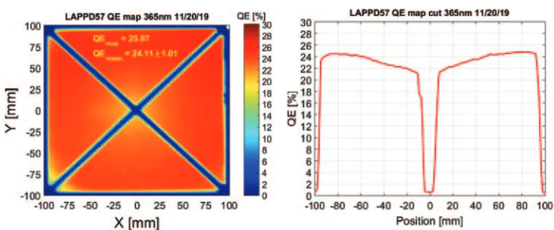
1.2.1. Photocathode QE. The process for large area bi-alkali (Na2KSb) photocathode
deposition is well established, routinely producing LAPPDs with a photocathode QE @365 nm≈ 25±2%, with good spatial uniformity which is generally within ±8%. Figure 1 shows the QE for LAPPD #57 which had a mean performance of 24.11±1.01% @365 nm, with a uniformity of≈±4%.
(1) Incom Inc. is a small privately held commercial firm located in Charlton, Massachusetts. The firm was founded 1971 and has a long history of product innovation.
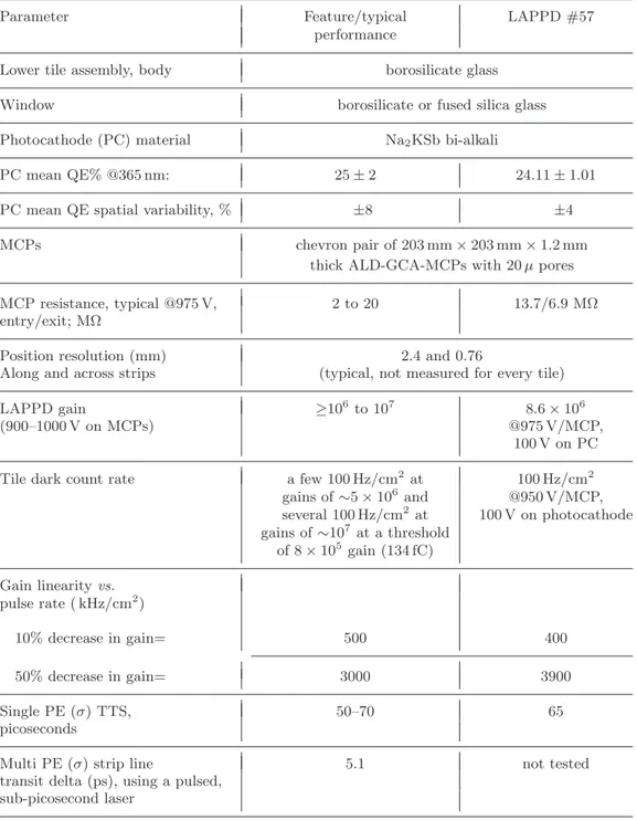
TableI. – GEN I LAPPD features and typical baseline performance.
Parameter Feature/typical LAPPD #57
performance
Lower tile assembly, body borosilicate glass
Window borosilicate or fused silica glass
Photocathode (PC) material Na2KSb bi-alkali
PC mean QE% @365 nm: 25± 2 24.11± 1.01
PC mean QE spatial variability, % ±8 ±4
MCPs chevron pair of 203 mm× 203 mm × 1.2 mm
thick ALD-GCA-MCPs with 20 μ pores
MCP resistance, typical @975 V, 2 to 20 13.7/6.9 MΩ
entry/exit; MΩ
Position resolution (mm) 2.4 and 0.76
Along and across strips (typical, not measured for every tile)
LAPPD gain ≥106to 107 8.6× 10⁶
(900–1000 V on MCPs) @975 V/MCP,
100 V on PC
Tile dark count rate a few 100 Hz/cm2 at 100 Hz/cm2 gains of∼5 × 10⁶ and @950 V/MCP, several 100 Hz/cm2 at 100 V on photocathode gains of∼107 at a threshold of 8× 10⁵ gain (134 fC) Gain linearity vs. pulse rate ( kHz/cm2) 10% decrease in gain= 500 400 50% decrease in gain= 3000 3900 Single PE (σ) TTS, 50–70 65 picoseconds
Multi PE (σ) strip line 5.1 not tested
transit delta (ps), using a pulsed, sub-picosecond laser
The baseline LAPPD can incorporate either a borosilicate (B33) or a fused sil-ica window, with typsil-ical photocathode QE spectral curves as shown in fig. 2. The fused silica window provides enhanced performance in the UV (80% transmittance above 230 nm).
Fig. 1. – A typical QE map is shown on the left, for LAPPD #57 which had a maximum QE @365 nm of 25.97% and a mean QE of 24.11± 1.01%. The image on the right shows a cut across the map, showing that the uniformity is≈±4% outside of the regions obscured by X-spacers.
1.2.2. Pulse height distribution and gain. The baseline GEN I LAPPD exhibits distinct peak separation from noise, typically 1.5–2× peak to valley ratio, in pulse height distri-butions with single photoelectron gains that range from high 106 to low 107. Figure 3
(left) shows the pulse height distributions for single photoelectrons for LAPPD #57 as a function of MCP voltage, with 200 V on the photocathode. On the right, the average gain vs. photocathode voltage at different MCP voltages is shown.
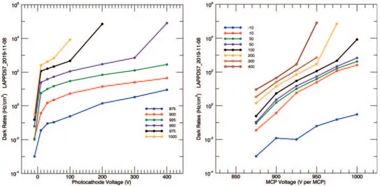
1.2.3. Dark rates vs. MCP and photocathode voltage. Dark rates are shown in fig. 4 for LAPPD #57 as a function of MCP voltage and photocathode voltage. These rates were acquired from a single 13.5 cm2 strip.
Photodetector dark count rates are affected by a number of variables including detec-tor design facdetec-tors as well as dark noise counts coming from the MCP. At room tempera-ture, the typical dark count from a chevron pair of conventional PbO MCPs is of the order of 1 count/cm2. Typical dark count rates for ALD-GCA-MCPs incorporating Incom’s
proprietary C14 and C5 capillary glass substrates are 0.03 and 0.05 counts/sec/cm2 re-spectively. The lower dark count rate for the Incom ALD-GCA-MCPs is a result of the chemical composition of the substrate glass, which, for both compositions, has less alkali (particularly less potassium K40) compared to conventional PbO MCPs. Incom’s C14
Fig. 2. – Typical photocathode QE spectral curve for a Borofloat (B33) window is shown on the left plot. Improved UV performance is shown for LAPPD incorporating fused silica windows, as shown in the plot on the right.
Fig. 3. – Gain is shown as a function of MCP voltage for LAPPD #57, with 200 V on the photocathode. Left: pulse height distributions. Right: average gain vs. photocathode voltage at different MCP voltages.
glass is substantially alkali free, which correlates with the lower dark count rates. Since a major contribution to detector dark counts comes from spontaneous thermally induced emissions from the photocathode, one means to separate MCP dark counts from other possible signal sources is to operate the LAPPD with the photocathode at a positive potential with respect to the nearby MCP, so the photocathode retains its photoelectrons. The dark rates of the MCPs obtained under these conditions are shown in the blue curve in the Dark Rate vs. MCP Voltage plot, fig. 4, right. The expected dark rates from thermal emission of the 20× 20 cm bi-alkali (Na2KSb) photocathode are of the order of
25–100 Hz/cm2.
If not adjusted properly, some combinations of MCP and photocathode voltages can
Fig. 4. – Dark rates are shown as a function of photocathode and MCP voltage for LAPPD #57.
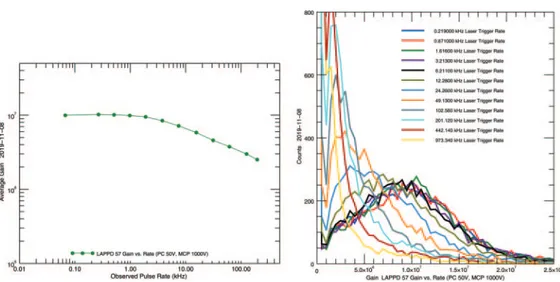
Fig. 5. – (Left) Gain is shown vs. observed pulse rate for single photoelectrons. (Right) The pulse distributions are shown as a function of laser trigger rate.
sharply increase the dark rates, and simultaneously create high voltage current instabili-ties and produce excess currents to ground within the LAPPD. Each LAPPD is provided with Recommended Operating Point (ROP) voltages which are selected by examination of the gain and dark rates as a function of MCP and photocathode voltage. The voltages are adjusted high enough to provide a gain in the mid-106(and above) range, short transit
time spread, while avoiding high dark rates and voltage-current instabilities. In general, despite its very large size, the GEN I baseline LAPPD has a predictable dark rate of only a few 100 Hz/cm2at gains of∼5 × 10⁶, ensuring lowest TTS and several 100 Hz/cm2at
gains of∼107.
1.2.4. Gain linearity vs. pulse repetition rate. The linearity of LAPPD response at a high repetition rate is determined by the ability of MCP strip current to neutralize space charge effects at the output of the “exit MCP”, that is, to recharge the microchannel [10]. The RC time constant of the microchannel limits the completeness of the recharge between pulses, and therefore the gain decreases at high rates. This causes weakening of the electric field and subsequently suppresses electron multiplication. MCPs with higher strip current would exhibit lower gain saturation at high repetition rates. The microchannel plates are suitable for high rate conditions because the channels operate nearly independently of each other, and unless the same channel is struck twice, they have time to recover. The reduction of gain as a function of rate was tested by applying the 405 nm laser to a spot on LAPPD 57 window, of about 1 mm in diameter. The repetition rate was changed, and the corresponding gain was measured.
Figure 5 (left) shows the gain as a function of observed pulse rate. As can be seen in the plots, the gain declines by a factor of approximately two as the observed rate is increased from ∼0.25 kHz to ∼31 kHz (32 kHz/cm2 to 3900 kHz/cm2), a gain decrease
from 9.8× 10⁶ to 4.9× 10⁶. A 10% gain decrease occurs at an observed rate of about
400 kHz/cm2. This rate is threshold-dependent, and at higher rates, some pulses fall below threshold.
Fig. 6. – The transit time variation is shown. This is the time difference between the observed laser firing and the arrival of the MCP pulse at the end of an anode strip. Right: the transit time variation is shown as a function of photocathode voltage, with an MCP voltage of 950 V/MCP and 400 volts between the “exit MCP” and the anode.
1.2.5. Timing characteristics. The 405 nm laser that is used in Incom LAPPD tests has a 21 ps FWHM firing window at the laser intensity used in the measurement. The intensity is reduced by a neutral density filter to produce single photoelectrons. There-fore, the laser photon that produces the single electron may arrive at any time within the 21 ps window. The transit time distribution is shown in fig. 6, left. The standard deviation of the distribution is 64.8 ps. If the variation of the laser photon has a standard deviation of (21/2.35) ps, then the LAPPD transit time variation may be extracted from the sum of squared variations formula (1) as 64.2 ps,
(1) σmeasured2 = σLAPPD2 + σLaser2 .
Single PE time resolutions in the 50–70 ps (σ) have been observed in multiple LAPPD consistent with timing reported for other commercial MCP-PMTs having comparable (20 μ) MCP pore size. Future LAPPD upgrades currently under development will in-corporate ALD-GCA-MCPs having 10 μ or smaller pore size MCPs and are expected to provide even better timing. In addition to pore size and design features of the pho-todetector, timing resolutions measured for LAPPD have been typically limited by the performance of the electronics available for those tests done at Incom.
At the Argonne National Laboratory, using a pulsed, sub-picosecond laser, the differ-ential time resolution between the signal reaching the two ends of the LAPPD delay line anode (with MCPs having 20 μ pore size), is reported to be 5.1 ps for large signals, with an asymptotic limit falling below 2 ps as noise-over-signal approaches zero [11].
2. – Positron emission tomography (PET)
Positron emission tomography (PET) is a medical diagnostic modality that is vital for oncological diagnosis and for guiding life-saving cancer treatments. Presently there
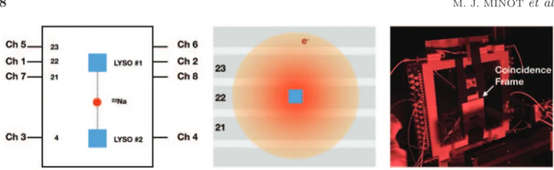
Fig. 7. – (Left) Two polished 3× 3 × 5 mm3 LYSO crystals wrapped in PTFE were set in coincidence on the LAPPD surface centered on strips 22 and 4, respectively. Signals at both strip outputs were recorded. (Middle) The signal is shared by three neighboring strips. (Right) Setup in the Incom dark box under red light.
are approximately 2 million scans/year in the US alone. Enhanced timing resolution contributes directly to improved signal-to-noise ratio (SNR) in the reconstructed im-age. Current clinical scanners offer a coincidence time resolution (CTR) of∼200–500 ps FWHM (FWHM≈ 2.35σ) while laboratory research in PET instrumentation has reached
<100 ps FWHM for small systems [12]. The medical community now targets high
pre-cision TOF-PET with the ability to operate in the regime of <50–100 ps FWHM time resolution with the ambitious long-term goal of reaching 10 ps FWHM (or 4.3 ps σ).
A very serious challenge is how to transfer these laboratory developments to a ro-bust and economical clinical imager system. It is in this regard that the LAPPD offers unique performance advantages based on the proprietary ALD-GCA-MCPs that are an enabling technology for these photodetectors. The large-area planar design of these photodetectors, the low cost/cm2, and excellent signal to noise performance make these
photodetectors uniquely attractive for PET application. In addition, the LAPPD’s large area coverage combined with relatively few high-frequency data acquisition system read-out channels enables very cost-effective TOF-PET system designs which may achieve very fine time resolution over needed large detector areas. Encouraged by this, we have undertaken the first efforts to evaluate and demonstrate the benefits of LAPPD for ap-plication in PET. An initial brief round of preliminary tests was undertaken at Incom using LAPPD #48. Based upon those results, LAPPD #57 was shipped to UC Davis, where additional testing is just getting underway.
2.1. Preliminary studies(2). – In its first demonstration of the LAPPD fitness for
PET application, preliminary measurement of the energy spectra produced by 511 keV photons from a 22Na radioactive source was made at the Incom facility. Two polished 3× 3 × 5 mm3 lutetium (yttrium) oxyorthosilicate (LYSO) crystals (Epic-crystal, China)
wrapped in PTFE were placed on the LAPPD surface and set in coincidence. While not yet optimized at the light collection and signal integration levels, good energy resolution was observed that also confirmed for the first time that the device can handle large numbers of scintillation photons without signal saturation. Excellent spatial resolution under 1 mm FWHM was measured in both coordinates.
(2) This section is based on a one-day preliminary study by Sun Il Kwon, Bill Worstell, Mark Popecki and Satya Butler, done at Incom Inc. (13 September 2019).
150 152 154 156 y-pos (mm) 0 1000 2000 3000 4000 Count -20 -10 0 10 20 x-pos in time (ps) 0 100 200 300 400 500 600 700 Count
Fig. 8. – Spatial resolution measurements using one of the LYSO pixels. Left: across the strips, from the center of gravity calculation on three strips (0.72 mm FWHM and 1.59 mm FWTM). Right: along the strip, from the timing difference in the signal arrivals at both ends of a strip (0.23 mm FWHM and 0.94 mm FWTM).
Figure 7 (left) shows the position of two polished 3×3×5 mm3LYSO crystals wrapped
in PTFE set in coincidence on the LAPPD surface centered on strips 22 and 4 (∼124 mm distance between two strips), respectively. Signals at both strip outputs were recorded. The signal is shared by three neighboring strips as shown in fig. 7, middle. The setup of LYSO crystals on the face of the LAPPD is shown in the Incom dark box, under red light.
Figure 8 shows the spatial resolution measurements using one of the LYSO pixels (left) across the strips, from the center of gravity calculation on three strips (0.72 mm FWHM and 1.59 mm FWTM), (right) along the strip, from the timing difference in the signal arrivals at both ends of a strip (0.23 mm FWHM and 0.94 mm FWTM). In the case of positioning along the strip, a constant of 11.4 ps/mm was used to convert time difference between both ends to a position. The constant value was derived by Incom through the measurement using the laser setup.
Figure 9 shows examples of two energy spectra measured from both ends of two central strips using 3× 3 × 5 mm3LYSO pixels. The measured energy resolution was about 20%
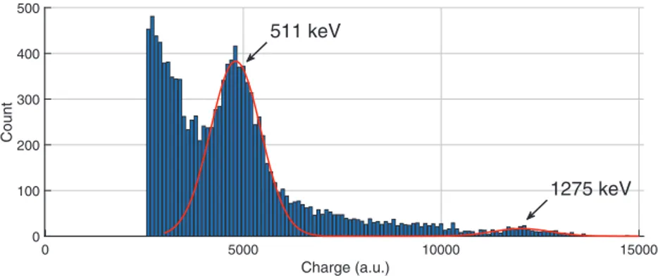
FWHM for the 511 keV photopeak. Figure 10 shows that the measured ratio between 1275/511 photo peaks center position was 2.50, as expected, showing that the operation was in the linear signal range, with no saturation.
3. – Discussion and conclusions
Routine pilot production of LAPPDs is now underway at Incom Inc. The availability of low cost, large area photodetectors that offer picosecond-scale timing is expected to have an important impact in many areas of application, from basic high energy and nuclear science to medical imaging. It is expected that as end users become more familiar with the benefits of this large area technology and the implications of picosecond-level timing, additional applications will be enabled, including for TOF-PET.
In the TOF-PET application, it is possible that long axial field of view LAPPD-based PET scanners that can image all the organs at once could be produced more
0 2000 4000 6000 8000 10000 Charge (a.u) 0 200 400 600 800 1000 1200 1400 Count Channel 3 0 2000 4000 6000 8000 10000 Charge (a.u) 0 200 400 600 800 1000 1200 1400 Count Channel 4
Fig. 9. – Examples of two energy spectra measured from both ends of two central strips using 3× 3 × 5 mm3LYSO pixels are shown. The measured energy resolution was about 20% FWHM for the 511 keV photopeak based upon integrating a large fraction of the still unoptimized signal.
cost-effectively. Dissemination of these large volume scanners is now limited by the prohibitive cost of the currently used PET imaging technology.
In the first demonstration of the LAPPD fitness for PET operation, preliminary measurements of the energy spectra produced by 511 keV photons and spatial resolution were made at Incom. While not yet optimized at the light collection and signal integration levels, good energy resolution was observed that also confirmed for the first time that the device can handle large numbers of scintillation photons within each scintillation pulse without signal saturation. Excellent spatial resolution under 1 mm FWHM was measured in both coordinates.
In summary, we believe that LAPPD, the world’s largest micro-channel-plate–based photomultipliers (MCP-PMTs), is a practical, affordable photosensor candidate to achieve precision timing, spatial and energy resolution across a range of light detection applications. 0 5000 10000 15000 Charge (a.u.) 0 100 200 300 400 500 Count 511 keV 1275 keV
Fig. 10. – The measured ratio between 1275/511 photo peak center position was 2.50, as expected.
∗ ∗ ∗
Incom development of LAPPD is currently supported by the U.S. Department of En-ergy, Office of Science, Office of Basic Energy Sciences, Offices of High Energy Physics and Nuclear Physics under DOE contracts: DE-SC0015267, DE-SC0017929, DE-SC0018778, and DE-SC0019821. U.C. Davis studies were supported by NIH grant R35 CA197608.
REFERENCES
[1] Adams B. W., Frisch H. J. et al., A brief technical history of the large-area picosecond photodetector (LAPPD) Collaboration, arXiv:1603.01843 (2016).
[2] Adams B., Chollet M., Elagin A., Oberla E. et al., Rev. Sci. Instrum., 84 (2013) 061301.
[3] Craven C. A. et al., Recent advances in large area microchannel plates and LAPPDTM, in Proceedings of International Conference on Technology and Instrumentation in Particle Physics 2017 (Springer) 2018, pp. 319–324, https://doi.org/10.1007/ 978-981-13-1316-5 60.
[4] Minot M. J. et al., Nucl. Instrum. Methods Phys. Res. A, 787 (2015) 78.
[5] Minot M. J. et al., Pilot production and advanced development of large-area picosecond photodetectors, in Proc. SPIE, Vol. 9968 (SPIE) 2016, https://doi.org/10.1117/12.2237331.
[6] Minot M. J. et al., Nucl. Instrum. Methods Phys. Res. Sect. A, 936 (2019) 527.
[7] Minot M. J., Popecki M. A. and Wetstein M. J., Large area picosecond photodetector (LAPPD) performance test results, in 2018 IEEE Nuclear Science Symposium and Medical Imaging Conference Proceedings (NSS/MIC), Sydney, Australia (IEEE) 2018, pp. 1–4, https://doi.org/10.1109/NSSMIC.2018.8824669.
[8] Ertley C. D. et al., Developments in large-area flat panel photodetectors with ALD glass capillary array microchannel plates, in Proc. SPIE, Vol. 11118, UV, X-Ray, and Gamma-Ray Space Instrumentation for Astronomy XXI (SPIE) 2019, https://doi.org/10.1117/12.2530039.
[9] Lyashenko A. V. et al., Nucl. Instrum. Methods Phys. Res. Sect. A, 958 (2020) 162834. [10] Fraser G. W. et al., Nucl. Instrum. Methods Phys. Res. A, 327 (1993) 328.
[11] Wetstein M. J. et al., Nucl. Instrum. Methods Phys. Res. A, 795 (2015) 1.
[12] FATA2019: FAst Timing Applications for nuclear physics and medical imaging, 3–5 September 2019, Accademia degli Zelanti e dei Dafnici, Acireale (Catania, Italy), https://agenda.infn.it/event/18991/timetable/.