Department of Computer Science and Engineering
Master Degree in Computer Engineering
ENHANCING QUALITY OF SERVICE
IN SOFTWARE-DEFINED NETWORKS
Supervisor: Professor Antonio CORRADI
Correlator: Professor Mario GERLA
Correlator: Professor Eduardo CERQUEIRA
Correlator: Doctor Luca FOSCHINI
Master’s Thesis of:
Francesco ONGARO
Academic Year 2013–2014
Session I
« Senza entusiasmo, non si è mai compiuto niente di grande. » RALPH WALDO EMERSON
Acknowledgements
« What lies behind us and what lies ahead of us, are tiny matters compared to what lies within us. » RALPH WALDO EMERSON
« Stay hungry, stay foolish. » STEVE JOBS
Anche se apparentemente i ringraziamenti sembrano casa di poco conto se comparati con l’intera tesi, alle volte richiedono uno sforzo di pensiero e medi-tazione notevole. Non si vorrebbe far dispetto a nessuno, ma si è perfettamente consapevoli di quali sono state le persone importanti e i momenti salienti che hanno contraddistinto questi anni di sacrificio. Seguendo questo percorso im-pegnativo, ora si è arrivati ad un momento conclusivo ed emozionante ma al contempo misterioso e fondamentale per ciò che verrà dopo. Un po’ come scol-linare a poco a poco una vetta dopo lunghe ore di intensa camminata, con vari momenti di apparente cedimento, ma con la forza e la voglia di arrivare in ci-ma per godersi lo spettacolo, rafforzato da quella sensazione di stanchezza e spossatezza tipiche dopo una lunga scarpinata.
“Time flies” i miei compagni alla UCLA mi dicevano diverse volte, e io dice-vo a loro con un velo di amarezza per l’avvicinarsi del momento del ritorno. Sì, partirei proprio dall’ultima esperienza, passata all’University of California, Los Angeles (UCLA) perché è il ricordo più fresco che ho in mente dato che sono
passate appena una manciata di settimane dal mio rientro. Questa affascinante esperienza, inizialmente misteriosa ma rivelatasi poi estremamente positiva e costruttiva, è stata resa possibile grazie al supporto della mia famiglia e del-le persone che mi sono state vicine prima e durante i mesi di permanenza a Los Angeles. Il Professor Antonio Corradi, a cui va un sentito ringraziamento per il supporto fornito prima e durante la tesi, ha inoltre reso possibile questa esperienza grazie ai numerosi contatti personali e al prestigio che l’Università di Bologna, seppur piccola confrontata con altri campus universitari, può van-tare ed essere orgogliosa di avere (oltre alla invidiata millenaria fondazione). Grazie inoltre al Professor Paolo Bellavista per i preziosi consigli e il suppor-to che immancabilmente mi ha fornisuppor-to anche a 10.000 km di distanza. Grazie all’Ingegner Luca Foschini, che ha contribuito alla tesi con interessanti spunti e consigli. All’interno della UCLA, un doveroso e sentito ringraziamento va al Professor Mario Gerla che mi ha ospitato come Visiting Researcher Scholar all’in-terno del proprio laboratorio, il Network Research Laboratory (NRL), rendendo la mia permanenza veramente piacevole e stimolante sotto il profilo accademico. Da Lui, così come dal Professor Leonard Kleinrock che ho avuto la fortuna di incontrare, ho imparato che si può essere “grandi” senza bisogno di dover dimostrare di esserlo. Durante la mia permanenza alla UCLA, ho avuto il pia-cere di essere inoltre seguito dal Professor Eduardo Cerqueira, che non solo si è dimostrato di notevole aiuto e supporto per la ricerca inerente alla tesi, ma ha contribuito allo svolgimento di numerosi meeting utili alla ricerca, nonché ha reso possibile l’instaurarsi di piacevoli momenti di aggregazione, sfociati in un vero e sentito rapporto personale di amicizia. Grazie anche al Professor Giovanni Pau che mi ha sempre fornito utili consigli e suggerimenti con una franchezza che poche persone hanno.
Ma la fine di questo percorso, contraddistinto dall’esperienza passata alla UCLA, non può scindersi da ciò che è venuto prima. E’ infatti vero e indiscuti-bile che, se si è arrivati sin qui, doverosamente si è dovuti passare per una serie di momenti e situazioni, piacevoli e dure allo stesso tempo, che tuttavia hanno reso possibile il raggiungimento di questo importante e gratificante traguar-do. Dice la guida alpina e scalatore M. Confortola: « se per cacciare un sogno e raggiungerlo servono forza, determinazione, costanza e un istinto
infallibi-le, è altrettanto vero che in montagna, come nella vita e nel lavoro, in vetta si arriva poco alla volta, campo base dopo campo base, rispettando i tempi e le fasi di acclimatamento ». Ecco quindi che i ringraziamenti li voglio dedicare nuovamente alla mia famiglia, che proprio in quegli anni mi ha continuamente supportato, spronato e aiutato, affinché potessi avvicinarmi ed arrivare in “vet-ta”. Lunghe e fondamentali passeggiate e chiacchierate con mio fratello Luca, che ben sa cosa vuol dire affrontare questo percorso universitario, mi hanno inoltre sempre aiutato, come un faro per i natanti, a mantenere costantemente la prua puntata nella giusta direzione, anche in difficili e burrascose situazioni. Sento inoltre dal profondo di ringraziare Giulia che in quegli anni mi è sempre stata vicina e immancabilmente ha creduto in me. Giulia è stata di grande aiuto affinché non gettassi mai la spugna ma, anzi, cercassi di arrivare fino alla fine del match.
Gli amici, anche se in tanti momenti ho purtroppo dovuto centellinare il tempo con loro per poter arrivare fin qui, è d’obbligo ringraziarli. Grazie per i momenti passati assieme e per gli aperitivi che hanno contraddistinto e scan-dito alcune nostre serate. Un abbraccio in particolare a Mattia, la cui amicizia e stima si perpetua da molti anni senza mai scolorire ma, anzi, impreziosendosi come un buon vino fa’ nella botte. Grazie inoltre a Gabri, France, Corne e Mo-ne per l’amicizia che ci lega da anni. Nonostante le diverse scelte di vita e la distanza che alle volte per mesi ci tiene distanti, riusciamo a trovare il tempo di incontrarci e condividere le nostre diverse esperienze. Credo che questa diver-sità sia un valore aggiunto per tutti noi. Inoltre, e ne sono orgoglioso, altre ami-cizie con ragazzi di diverse parti del Mondo sono nate all’interno dell’NRL alla UCLA. Dunque un particolare grazie va all’amico Paul-Louis, al mitico “big” Vince, a Ronedo, a Jerrid e agli altri ragazzi, per aver trascorso preziosi minuti in compagnia davanti a un buon caffè (italiano) o seduti ad un tavolo a gustare piatti messicani o burger americani. “Last but not least”, sento di ringraziare l’Ingegner Giulia Mauri, che negli ultimi mesi alla UCLA mi ha aiutato nella stesura della tesi con preziosi consigli e correzioni. Ritengo, inoltre, che Giulia abbia contribuito a rendere unica e irripetibile questa esperienza oltreoceano.
Giusto poche parole sulle due frasi citate in alto. La frase di Ralph Waldo Emerson, filosofo e scrittore statunitense dell’ottocento, penso sia emblematica
e, personalmente, la condivido appieno: « ciò che abbiamo alle spalle e quello che ci sta di fronte, sono cose di poco conto rispetto a ciò che sta dentro di noi ». Essa evidenzia che la persona che siamo diventati e quindi ciò che si ha dentro, la si deve alle innumerevoli scelte, azioni ed esperienze che si sono fatte durante la propria vita. Questo “patrimonio” dunque, ci suggerisce Ralph Waldo Emerson, ha un valore inestimabile ed è unico in ognuno di noi. Esso ci dà la forza di guardare al futuro, anche se pieno di difficoltà e incertezze, e al contempo di sorridere al passato, che sicuramente sarà stato caratterizzato da sfide e ostacoli, con fierezza e fermezza. Dunque ciò che abbiamo dovuto affrontare in passato e quello che il futuro ci riserverà, sono cose di poco conto (“tiny”) rispetto alla ricchezza che abbiamo maturato dentro di noi.
Riprendo inoltre la celebre frase di Steve Jobs pronunciata ai neolaureati dell’Università di Stanford durante la cerimonia di laurea : « siate affamati, sia-te folli ». Essa si riferisce all’approccio che si dovrebbe avere alla propria vita, cercando di viverla e spremerla affinché si riesca a trovare la propria strada senza che nessuno possa imporci le proprie ideologie o limitare la nostra crea-tività e il nostro essere. Personalmente, ritengo questo aspetto di fondamentale importanza nella propria vita.
Sommario
La gestione delle risorse è problema di primaria importanza nelle reti di calcolatori e rimane tuttora un aspetto non risolto e da tenere in considerazio-ne. Sfortunatamente, mentre la tecnologia e l’innovazione evolvono, la nostra infrastruttura di rete è rimasta praticamente nella stessa condizione per de-cenni, dando origine a quello che comunemente viene definito fenomeno di “ossificazione di Internet”.
Il Software-Defined Networking (SDN) è un paradigma emergente nel cam-po delle reti di calcolatori e consente di controllare, tramite un software centra-lizzato a livello logico, il comportamento dell’intera rete.
Tale gestione è resa possibile attraverso il disaccoppiamento tra la logica di controllo che governa la rete e l’infrastruttura fisica sottostante di switch e rou-ter adibiti all’instradamento del traffico. Il meccanismo che permette al piano di controllo di poter comunicare con il piano dei dati è OpenFlow. Gli operatori che si occupano delle reti sono dunque in grado di scrivere programmi di alto livello per il controllo del comportamento dell’intera rete. Inoltre, la centraliz-zazione del piano di controllo permette di definire complesse operazioni da eseguire sulle reti, relative ad esempio alla sicurezza o alla gestione e controllo delle risorse, attraverso un unico strumento.
Oggigiorno, l’esplosione delle applicazioni usufruite in tempo reale che hanno delle caratteristiche limitanti di Qualità di Servizio (QoS), porta i pro-grammatori delle reti a dover progettare protocolli che garantiscano adeguate prestazioni. La tesi sfrutta le SDNs e l’utilizzo di OpenFlow per gestire nelle reti
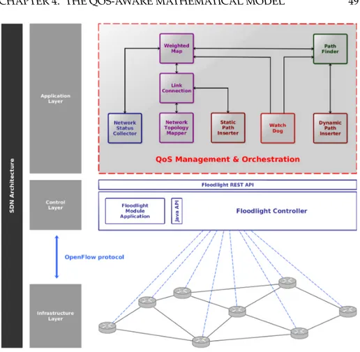
servizi differenziati con una elevata QoS. Inizialmente abbiamo definito un’ar-chitettura per la gestione e l’orchestrazione della QoS che permetta di gestire la rete modularmente. Inoltre, viene fornita una integrazione tra l’architettura presentata e il paradigma definito dalle SDN, mantenendo la separazione tra il piano di controllo e quello dei dati.
Il nostro lavoro rappresenta una prima fase di configurazione della rete presso la UCLA (University of California, Los Angeles) in grado di offrire ser-vizi differenziati e stringenti requisiti di QoS. Abbiamo inoltre pianificato di sfruttare la nostra soluzione per gestire l’handoff tra differenti tecnologie di rete, i.e., Wi-Fi e WiMAX. Infatti, il modello può essere eseguito utilizzando di-versi parametri, dipendenti dal protocollo di comunicazione usato, ed è in gra-do di fornire risultati ottimali che possono essere direttamente implementati in una rete di campus universitario.
Abstract
Resource management is of paramount importance in network scenarios and it is a long-standing and still open issue. Unfortunately, while technol-ogy and innovation continue to evolve, our network infrastructure system has been maintained almost in the same shape for decades and this phenomenon is known as “Internet ossification”.
Software-Defined Networking (SDN) is an emerging paradigm in computer networking that allows a logically centralized software program to control the behavior of an entire network. This is done by decoupling the network control logic from the underlying physical routers and switches that forward traffic to the selected destination. One mechanism that allows the control plane to communicate with the data plane is OpenFlow. The network operators could write high-level control programs that specify the behavior of an entire net-work. Moreover, the centralized control makes it possible to define more spe-cific and complex tasks that could involve many network functionalities, e.g., security, resource management and control, into a single framework.
Nowadays, the explosive growth of real time applications that require strin-gent Quality of Service (QoS) guarantees, brings the network programmers to design network protocols that deliver certain performance guarantees. This thesis exploits the use of SDN in conjunction with OpenFlow to manage differ-entiating network services with an high QoS. Initially, we define a QoS Man-agement and Orchestration architecture that allows us to manage the network in a modular way. Then, we provide a seamless integration between the
tecture and the standard SDN paradigm following the separation between the control and data planes.
This work is a first step towards the deployment of our proposal in the University of California, Los Angeles (UCLA) campus network with differen-tiating services and stringent QoS requirements. We also plan to exploit our solution to manage the handoff between different network technologies, e.g., Wi-Fi and WiMAX. Indeed, the model can be run with different parameters, depending on the communication protocol and can provide optimal results to be implemented on the campus network.
Contents
1 Introduction 2
2 Background 6
2.1 Software-Defined Network paradigm . . . 6
2.1.1 Motivation . . . 6
2.1.1.1 “Classical” switch . . . 7
2.1.2 Early Programmable Networks . . . 8
2.1.2.1 Intelligent Network . . . 8 2.1.2.2 OPENSIG . . . 10 2.1.2.3 GSMP . . . 11 2.1.2.4 Active Network . . . 11 2.1.2.5 4D architecture . . . 12 2.1.2.6 NETCONF . . . 13 2.1.2.7 ForCES . . . 13 2.1.2.8 Ethane . . . 13 2.1.3 SDN Architecture . . . 14 2.1.3.1 Logical layers . . . 15 2.1.3.2 SDN switch . . . 16 2.2 OpenFlow protocol . . . 17 2.2.1 Operating principles . . . 18 2.2.1.1 “Instruction Set” . . . 19
2.2.2 Flows based operation . . . 20
2.2.3 Evolution summary . . . 20 2.2.4 Switch components . . . 22 2.2.4.1 Pipeline processing . . . 24 2.2.4.2 Packet matching . . . 24 2.2.4.3 Table miss . . . 25 2.2.4.4 Flow Entry . . . 26 2.3 Control models . . . 27 2.3.1 Flows insertion . . . 27
2.3.2 Control plane distribution . . . 28
2.4 SDN weaknesses and challenges . . . 28
2.5 Floodlight SDN Controller . . . 30
2.5.1 Architecture . . . 30
3 Dealing with SDN 34 3.1 Related work . . . 34
3.1.1 How to Monitor Network Parameters with OpenFlow . 35 3.1.2 SDN to improve Quality of Service and Quality of Expe-rience . . . 37
3.2 Mininet Network Emulator . . . 41
4 The QoS-aware Mathematical Model 44 4.1 Enhanced QoS Architecture . . . 48
4.2 Multi-Criteria Approach . . . 51
4.2.1 Multi-Commodity Flow Problem . . . 51
4.2.2 Constrained Shortest Path Problem . . . 53
4.2.3 Our Multi-Commodity Flow and Constrained Shortest Path Model . . . 55
5 Implementation and Experimental Results 60 5.1 Hardware Configuration . . . 62
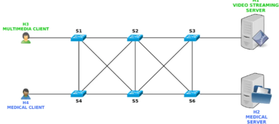
5.2 Network Topology . . . 63
5.3 Mininet Configuration . . . 64
5.4 Mininet Hybrid Configuration . . . 65
5.4.1 Network Services and Tools . . . 67
5.5 Mapping the Network . . . 69
5.6 Inserting the Path . . . 69
5.7 Network Metric Measurement . . . 70
5.7.1 Available Bandwidth . . . 71
5.8 Results . . . 72
6 Conclusion 88 6.1 Future Work . . . 90
A Python Code 94 A.1 Network Topology Configuration . . . 94
List of Figures
2.1 “Classical” switch components . . . 8
2.2 Intelligent Network Conceptual Model [1] . . . 9
2.3 4D Project Architecture . . . 12
2.4 ForCES Architecture . . . 14
2.5 Ethane Architecture . . . 14
2.6 SDN Architecture . . . 15
2.7 SDN switch components . . . 16
2.8 OpenFlow switch specification [3] . . . 17
2.9 Packets treatment by the switches OpenFlow-enabled . . . 19
2.10 OpenFlow Instruction Set [2] . . . 20
2.11 OpenFlow evolution summary . . . 21
2.12 OpenFlow switch components [4] . . . 23
2.13 Pipeline packets matching [4] . . . 24
2.14 Packet flow matching [4] . . . 25
2.15 Floodlight architecture [5] . . . 30
3.1 The model of an OpenFlow switch . . . 36
3.2 The functional architecture of the latency monitoring application 37 3.3 OpenFlow-assisted QoE Fairness Framework . . . 39
4.1 Streaming quality and packet loss rate (in percentage) for differ-ent contdiffer-ent types [6] . . . 47 4.2 QoS Management & Orchestration architecture (red dashed line) 49
5.1 Delay in a real packet-switched network [7] . . . 61
5.2 Network topology model . . . 63
5.3 Mininet hybrid topology network . . . 66
5.4 Floodlight QoS Advisor v.0.2a . . . 68
5.5 Throughput measurement using Iperf tool in the different sce-narios (100Mbps network). . . 73
5.6 Throughput measurement using both the Iperf tool and our mod-ule with no packet loss . . . 74
5.7 Throughput measurement using both Iperf tool (server side) and our module with 4% of packet loss . . . 74
5.8 Bandwidth usage during the video streaming service. . . 75
5.9 Temporary network congestion during the video streaming ser-vice. . . 75
5.10 Video streaming and file transfer throughputs during a tempo-rary link congestion. . . 76
5.11 Video streaming and file transfer throughputs during a perma-nent link congestion. . . 76
5.12 Video steaming and file transfer paths in a network without QoS. 77 5.13 Warnings due to a under-threshold throughput. . . 79
5.14 The “Watch Dog” Flow Chart . . . 80
5.15 Path changing by the QoS architecture during a permanent link congestion. . . 81
5.16 Video streaming throughput during a permanent link conges-tion in a network managed by the QoS architecture. . . 81
5.17 Multiple path changing by the QoS architecture during a multi-ple link congestion. . . 82
5.18 Video streaming throughput during a multiple permanent link congestion in a network managed by the QoS architecture. . . . 82
5.19 Path changing by the QoS architecture during a permanent link congestion. . . 83
5.20 Multi-Commodity Flow throughput during a permanent link congestion in a network managed by the QoS architecture. . . . 83
List of Tables
2.1 Flow entry fields [4] . . . 26
4.1 Application quality requirements . . . 44
4.2 Mean Opinion Score levels [8] . . . 45
4.3 Voice connectivity total delay (one-way) [9] . . . 46
4.4 End-To-End delay in the network gaming [10] . . . 46
4.5 QoS requirements of VoIP, Interactive-Video, and Streaming-Video [11] . . . 47
5.1 Conversion between our mathematical model cost and the MOS levels related to the video streaming . . . 84
Chapter
1
Introduction
The currently used network infrastructure system has been maintained al-most in the same form for decades, while technology continues to evolve. Re-source management is of paramount importance in network scenarios and it is a long-standing and still open issue. Moreover, in this scenario, the main issue to deal with is the decoupling of the network control logic from the data plane of the network, i.e., the physical routers and switches that forward traffic from sources to destinations. Since there are a lot of emerging network paradigms that are trying to find an efficient alternative to the classical Internet archi-tecture, only a few of them are widespread and successful. In this contest, the Software-Defined Networking (SDN) [2] paradigm is one of the best and most attractive solutions for improving the Internet with more flexibility and adaptability issues. This emerging networking paradigm allows a centralized software program to control the behavior of the whole network by separat-ing the routseparat-ing decision plane from the forwardseparat-ing layer. The SDN paradigm needs a mechanism to make the communications between the control and data plane possible. This functionality is obtained by means of an emergent pro-tocol, OpenFlow [3]. SDN, in conjunction with OpenFlow, allows us to write high-level control programs that specify the behavior of the network compo-nents. These programs can take care of various network tasks, e.g., security, routing, and resource management.
These tasks are among the most important aspects in all network scenarios, 2
since the main Internet services are generally still based on the classic Best-Effort paradigm. On the one hand, the Best-Best-Effort service is simple and its simplicity has been the most important factor which has determined its world-wide success. On the other hand, unfortunately, the Best-Effort service does not provide any guarantee on bandwidth, end-to-end delay, and packet loss. Fur-thermore, nowadays the demand of quality associated to the transport of data and media is growing both in academia and industry. This need represents a very hard challenge and it requires a significant effort towards a QoS-enabled network.
Traditionally, the QoS is defined in terms of availability, i.e., the percentage of time in which the reference system is available and working. In this way, the Service Level Agreements (SLAs) have been defined as a function of percentage availability, e.g., 99.999%, known as “five nines”, that implies a downtime of 5.26 minutes per year. The downtime is the amount of time required to identify and repair a fault in the connection or in the equipment. Furthermore, it is very important to understand that each type of service has different SLA require-ments, not only based on availability. Hence, the advanced SLA has to take into account the packet delay and the packet loss parameters in addition to the availability. It follows that the quality of some types of applications depends on delay and/or packet loss (e.g., real-time applications or multimedia trans-missions). On the one hand, the telephony services (e.g., VoIP) have strict delay requirements for the packet and codec. In these applications, if a packet reaches its destination after a given delay threshold, the service becomes useless. For the real-time applications, the retransmission of lost packets is also worthless. On the other hand, we have other types of applications that are called elastic. In general, these services are more robust than real-time applications related to packet loss. In fact, they typically allow retransmission, usually accomplished in an end-to-end fashion through the TCP mechanisms. For instance, the File Transfer Protocol (FTP) services and more generally (even if not always) the data transfer applications are referred to as elastic.
It is not easy to guarantee QoS requirements in the traditional Best-Effort networks. Regarding this, the Internet Engineering Task Force (IETF) [12] has proposed different QoS architectures, such as IntServ [13] and DiffServ [14], in
the last decades. However, these proposals have not been very successful or implemented in a wide scale, because they require some fundamental changes on Internet design. In the current Internet architecture, there is also a severe lack of information about the available network resources from the end-to-end point of view. A partial solution came from the Multiprotocol Label Switch-ing (MPLS) and the Border Gateway Protocol (BGP) techniques [15] that are defined to solve these problems. Unfortunately, these solutions lack the real-time reconfigurability and adaptivity. In this scenario, the SDN paradigm can be a fundamental key to overcome the current Best-Effort limitations explained above.
This thesis exploits the use of OpenFlow in SDNs to manage differentiating network services with a high QoS. In particular, we consider a Video Streaming service and a Data Transfer service. Firstly, we define a QoS Management and Orchestration architecture that allows us to manage the network in a modular way. Secondly, we provide a seamless integration between the architecture and the standard SDN paradigm following the separation between the control and data planes.
Then, we give an Integer Linear Programming (ILP) formulation of the problem of guaranteeing a good QoS in terms of packet loss and delay, taking into account the constraints of the network, i.e., maximum acceptable packet loss and delay for each type of service and available bandwidth on the links. Specifically, our model defines a Multi-Commodity Flow Constrained Shortest Path (MCFCSP) problem and takes advantage of both the well known prob-lems derived from Operation Research: the Multi-Commodity Flow Problem (MFP) and the Constrained Shortest Path (CSP). Given the optimal solution of the problem, we integrate the results with an emulated network by means of Mininet [16]. Thus, it is possible to map the different network flows on a real network based on the optimal solution from the model. Moreover, we define various levels of QoS, according to the MOS system [8] for the services that we are considering. Finally, we found a connection between the optimal solution provided by the model and the MOS levels. We used these results to provide evidence of the effectiveness of our model compared to the traditional solu-tion given by the emulator. Then, changing the network condisolu-tions, it is easy
to find the new optimal routes between source and destination by means of the model. It is also possible to dynamically map the routes into the network and, most important, to guarantee the QoS necessities.
This work is a first step towards the deployment of our proposal in the University of California, Los Angeles (UCLA) campus network with differen-tiating services and stringent QoS requirements.
Thesis Outline
This thesis describes a new architecture that allows enhanced QoS in SDN networks. The architecture is composed of several modules that give us the possibility to retrieve information about the network status and manage the switches according to our mathematical model. The remainder of the thesis is structured as follows:
• Chapter 2 provides an overall view about the SDN paradigm, starting from the early solutions that laid the foundation for SDN and then focus-ing on the OpenFlow protocol characteristics. The SDN weaknesses and the Floodlight controller are also presented.
• Chapter 3 gives an overview of the state of the art and presents Mininet, an emulated environment suitable for dealing with SDN.
• Chapter 4 describes our novel architecture that makes an enhanced QoS model in SDN networks possible. This chapter also details the mathe-matical model in depth, based on the Multi-criteria approach, which is the core of our architecture.
• Chapter 5 provides the implementation of the proposed architecture and also the performance assessment and the numerical evaluation.
Chapter
2
Background
2.1 Software-Defined Network paradigm
S
ofware-Defined Networking (SDN) was conceived at the UC Berkeley and Stanford University in 2008. The Open Networking Foundation (ONF) [17], a non-profit industry consortium founded in 2011, is dedicated to the promotion and adoption of SDN through open standards development like as OpenFlow™ protocol. The purpose of this chapter is to give a brief overview of the SDN architecture, paradigm, and protocol.2.1.1 Motivation
The term Internet ossification [18] expresses the difficulty of the Internet to evolve in terms of both its physical infrastructure as well as its protocols and performance. The Internet is considered part of our society critical infrastruc-ture and it has a huge deployment base (like as in transportation, power grids, water supply, etc.) that makes its evolution not simple. Furthermore, it is im-perative that the Internet would be able to evolve to address new challenges as represented by new applications and services that are becoming increasingly more complex and demanding.
With a more detailed view, in current networks, it is very hard to deploy new protocols, services, resources optimization, and traffic differentiation, be-cause the routers and the switches are usually “closed” systems, often with
limited functionalities and vendor-specific control interfaces. Furthermore, the lack of a common control interface to the various network devices may require high efforts for the configuration or the policy enforcement of them. Thus, it is more difficult for the network infrastructure to evolve, once it has been de-ployed and in production. Nevertheless, “middleboxes” like as firewalls, Intru-sion Detection Systems, and Network Address Translators, were used to over-come, in a “workaround way”, these limitations and circumvent the network ossification effect.
The network infrastructure ossification issues are largely attributed to the tight coupling between the control logic and the forwarding hardware which means that the decisions about the data flowing through the network are taken directly on-board from each “classical” network device.
2.1.1.1 “Classical” switch
In a classical router or switch, the fast packet forwarding (data plane) and the high level routing decisions (control plane) occur on the same device, as depicted in Figure 2.1. In this figure, the main components respectively are:
1. The forwarding elements are generally Application-Specific Integrated
Circuits (ASIC), network-processors, or general-purpose processor-based
devices that handle data path operations for each packet. They are de-signed to perform very quickly one particular function: to forward frames and packets at wire speed (line-rate). Furthermore, they are able to in-crease the lookup functions using very specialized memory resources like as Content Addressable Memory (CAM) or Ternary Content
Address-able Memory (TCAM) to hold the forwarding information.
2. The control elements in general are based on general-purpose processors that provide control functionalities, like routing and signaling protocols. The main difference between a “classical” switch and a switch able to work on an SDN network, is the architecture, as explained further below. However, before explaining the details of the SDN architecture, we focus on pioneer works that had provided inspiration for the SDN. In these works, the funda-mental keys had been the decoupling of control plane from data plane and the
Figure 2.1: “Classical” switch components
network programmability, as explained in the next section.
2.1.2 Early Programmable Networks
The following chapter discusses the “early programmable networks”, start-ing from the Eighties to nowadays. In the 1980s, the idea of centralized and decoupled control network started in the telecommunication field with the In-telligent Network architecture. Then, in the mid 1990s, the programmable net-work principles were established with some projects, precursors of the current SDN paradigm.
2.1.2.1 Intelligent Network
The Intelligent Network (IN) was an architectural concept, introduced by the Bell Communications Research group, that was applied to the develop-ment of new services in wireline telephone. IN enables the real-time execution of network services and customer applications in a distributed environment. Through separation between the software that controls the basic switch func-tionalities and the software that controls the call progression, the main goal was the rapid development of differentiating services. Furthermore, the main components of the IN architecture are depicted in Figure 2.2 and they rep-resents a framework called Intelligent Network Conceptual Model (INCM). Specifically, the INCM model is composed of four planes, as described in [19]:
1. The Service Plane (SP) describes services from the user prospective. It consists of one or more Service Features (SF) that represent a service
Figure 2.2: Intelligent Network Conceptual Model [1]
component. Furthermore, a service component can be a complete service or part of a service. This composition principle can make the services cus-tomization by the subscribers instead of the telco operators possible. 2. The Global Functional Plane (GFP) deals with service creation and
mod-els the network as a unique and global virtual machine. This plane con-tains the Service Independent Building Blocks (SIB) that are a set of standard and reusable capabilities used to build features and services. Furthermore, the Basic Call Process (BCP) is a SIB from which a service is launched. In this plane, a service consists of a chain of SIBs which can be viewed as a script.
3. The Distributed Functional Plane (DFP) defines the functional architec-ture. It is composed of a set of Functional Entities (FE) that realize the network functionalities. The main functions of this plane are:
a. The Service Control Function (SCF) that contains the service logic and controls the execution of the service.
b. The Service Switching Function (SFF) that provides a standardized interface between the SCF and the switch, allowing the control of them.
c. The Specialized Resource Function (SRF) that performs user inter-action functions through established connections.
d. The Service Data Function (SDF) which performs related data pro-cessing function used to update and retrieve user information. e. The Service Management Function (SMF) that handles the
activi-ties related to the service deployment, service control, service mon-itoring, service provisioning, and service billing.
f. The Service Creation Environment Function (SCEF) which allows the service definition, development, and testing on the network. 4. The Physical Plane (PP) corresponds to the physical architecture of the
IN and it is composed of the Physical Entities (PE) and the interfaces among them. Furthermore, the FE entities of the DFP plane are directly implemented into the PE in the PP plane and the interactions among different PEs are possible through the Intelligent Network Application
Protocol (INAP).
Thus, the IN architecture is based on a centralized control and the service con-trol is completely separated from call concon-trol as happens in the SDN networks. The Open Signaling Working Group also presented an architecture to make the network programmability possible, as explained in the next section.
2.1.2.2 OPENSIG
At the beginning, the Open Signaling Working Group (OPENSIG), pro-posed a solution based on an open and programmable network interface to access the network hardware. The motivation originally came from the obser-vation that monolithic and complex control architectures could be restructured as a minimal set of layers. By means of this partition and by using an open interface, it became possible to easily access the services located in each layer. This approach was used to introduce programmability in the control plane of the telecommunication networks based on ATM [20]. Furthermore, an IETF
group understood the need to define a common protocol, called GSMP, suit-able for the network device management.
2.1.2.3 GSMP
Starting from the programmable network interface idea, an IETF working group developed the General Switch Management Protocol (GSMP), a pro-tocol specifically designed for the management of the switches by external components. Furthermore, the protocol allows the external controller to get network statistic information, manage connections, ports, and resources of the switches [21]. GSMP v. 3 is the last version of the protocol, published in June 2002. Another important networking group, Active Network, also defined a novel architecture to improve the network programmability, as detailed above.
2.1.2.4 Active Network
Around 1997, the Active Networking Group proposed an innovative pro-grammable network architecture approach, named Active Network, in which the switches perform customized operations on the data messages flowing through them [22]. The main objective was to decouple network services from the hardware allowing the loading of new services into the infrastructure by need. The network is considered “active” in the sense that the switches can perform computation on the packet contents. Moreover, there are two different approaches to build active networks that are respectively considered “discrete” (out-of-band) and “integrated” (in-band) [23]:
1. The “programmable switch” approach is based on the injection of cus-tomized programs into the active nodes (switches or routers). Through the examination of the message header, the specific programs can pro-cess the packets and perform computations like as: modify, store or redi-rect the data. In the Internet based on the Active Network architecture, it is possible to dynamically load code into the nodes through a “back door”, achieving a router extensibility purpose. It follows that the main goal of this approach is focused on the separation between the injection programs and the processing of the messages.
2. The “capsules” approach is based on the possibility to embed a program fragment and data into every packet (called capsule). Therefore, when a capsule reaches an active node, the node is able to evaluate and process the embedded code.
These approaches aim to make the basic network services selectable on a per packet basis, reducing the deployment time and allowing the network pro-grammability. Moreover, about ten years ago, another architecture was devel-oped to reach a flexible network programmability by decoupling the data plane and control plane, as described below.
2.1.2.5 4D architecture
In the mid of 2000, the 4D architecture [24] was developed with a clear separation between the routing decision logic and the protocols governing the interaction with the network elements. As depicted in Figure 2.3, the network control functions are divided into 4 planes: decision, dissemination, discovery, and data.
Figure 2.3: 4D Project Architecture
In the 4D architecture, each plane has a clear task:
1. The decision plane is responsible for the network configuration through the management of the router Forwarding Information Base.
2. The dissemination plane is accountable for the network state informa-tion gathering such as link up/down informainforma-tion.
3. The discovery plane enables devices to discover their directly connected neighbors.
4. The data plane is responsible for the network traffic forwarding.
This architecture provides direct inspiration for later works such as NOX (Network Operating System), which proposed an “operating system for net-works” that provides an uniform and centralized programmatic interface to the entire network [25]. Moreover, the IETF Network Configuration Working Group presented a protocol to make the network configuration possible.
2.1.2.6 NETCONF
In 2006, the IETF Network Configuration Working Group proposed the
NETCONF Configuration Protocol [26]. NETCONF protocol was not designed
for enabling direct control of the switches, but as a management protocol for modifying the configuration of the network devices by means of API. Unfortu-nately, in this solution there is no separation between the data and the control plane. However, the ForCES IETF group developed an architecture and a pro-tocol to separate the forwarding plane from the routing plane.
2.1.2.7 ForCES
The IETF Forwarding and Control Element Separation (ForCES) Work-ing Group defined the architectural framework and the associated protocols to standardize the exchange of information between the control and forwarding plane [27]. This approach, drawn in Figure 2.4, aims to improve the interoper-ability and flexibility enabling a rapid innovation in the control and forwarding planes. Since 2003, the ForCES protocol has been undergoing standardization.
The next section also present the Ethane architecture that is considered as the predecessor of the OpenFlow protocol, laid the foundation for what SDN would become.
2.1.2.8 Ethane
The Ethane project [28] defines a new network architecture for enterprise networks, started around 2006. The network is composed of the Ethane swit-ches, that include the flow tables, and the controller. By means of a secure chan-nel, the controller can communicate with the switches and can decide whether
Figure 2.4: ForCES Architecture
a packet should be forwarded or not. As depicted in Figure 2.5, the Ethane architecture is composed of an external and centralized controller that can in-teract with the Ethane switches for managing policy and security.
Figure 2.5: Ethane Architecture
As we can clearly see in Figure 2.5, the Ethane architecture makes the sepa-ration between the control plane and the data plane possible. This is an impor-tant aspect that is the core of the SDN architecture, as detailed above.
2.1.3 SDN Architecture
In the following section, we are interested in explaining the main compo-nents of the SDN architecture. The SDN architecture represents a new
network-ing paradigm that decouples the control plane from the data plane, facilitat-ing the network evolution, interoperability, and scalability. This decouplfacilitat-ing, that is the SDN “core”, is possible through the switch components separation, as explained further in Section 2.1.3.2. Furthermore, the main differences be-tween the “classical” network and the new networking paradigm are described through three different logical layers as detailed below.
2.1.3.1 Logical layers
The SDN architecture can be represented by three different logical layers [2], as shown in Figure 2.6.
Figure 2.6: SDN Architecture
Specifically, each tier has different functionalities:
1. The data plan tier portrays the network infrastructure composed of phys-ical devices (e.g., switches and routers).
2. The controller tier represents the “network intelligence” and it is logi-cally centralized in the SDN controller, virtually located in this layer. This solution allows the controller to maintain a global view of the network, placed in the infrastructure layer.
3. The application tier represents the layer where network operators and administrators can operate. By centralizing the network state in the con-troller tier, at the application layer it is possible to configure, manage,
secure, and optimize network resources via dynamic, automated SDN programs. Moreover, the network operators can directly write and de-ploy customized programs themselves without waiting for the vendors releases that could take long time.
Hence, the layers abstraction described above facilitates the programmers to operate on a network abstraction layer instead of thousands of different phys-ical devices, through Application Programming Interfaces (APIs). However, this abstraction is possible only if the under layer infrastructure makes the in-teraction with itself possible. To reach this goal, the SDN architecture requires physical devices with different characteristics compared with the “classical” switch, as explained in the next section.
2.1.3.2 SDN switch
On the one hand, by means of the SDN architecture, the network becomes a “simple” packets forwarding element. On the other hand, the high-level rout-ing decisions and state information are centralized in an external and separate server controller, instead of enforcing policies and running protocols on a con-volution of scattered devices, as shown in Figure 2.7.
Figure 2.7: SDN switch components
SDN, by separating the control plane from the data plane, can offer a flexi-ble network automation and management framework. This framework makes the development of tools for automating tasks (that are done manually today) possible. These automation tools can reduce operational overhead decreasing network instability introduced by operator error. Unfortunately, the vendors
software environments is typically proprietary and closed and they do not make the management and tweaking of the network easy. However, the SDN architecture can facilitate innovation and enable simple programmatic control of the network data-path giving rise to the idea of programmable networks. This is an important aspect that allows to lower the barrier to the entrance for new ideas.
Clarified the architecture, described further in Section 2.2.4, the next section explains how it is possible to communicate among the different layers.
2.2 OpenFlow protocol
OpenFlow™ is an open standard protocol, specifically designed for the SDN networks, that allows the communication between the control and data planes and permits the manipulation of the latter. As illustrated in Figure 2.8, the OpenFlow switches and the controller can communicate via the OpenFlow protocol over a secure channel. The protocol defines different messages such as packet-received, send-packet-out, modify-forwarding-table, and get-stats, that can be exchanged between the switch and the controller.
Figure 2.8: OpenFlow switch specification [3]
At the beginning, the OpenFlow protocol was developed at the Stanford University around 2008 for enabling researchers to run experimental
proto-cols in the campus networks [3]. Presently, OpenFlow is added as a feature to commercial network devices and it provides a standardized vendor-agnostic interface to access the Ethernet switches, routers and wireless access points. Moreover, these devices, called “OpenFlow-enabled”, allow the access without requiring vendors to expose the internal workings of their products. Thus, the OpenFlow protocol makes the deployment of innovative routing and switch-ing protocols easy. Furthermore, it can be used for applications such as virtual machine mobility, high-security networks and next generation IP-based mobile networks.
The next sections describe the OpenFlow operativeness in depth, starting from a general overview, proceeding with the protocol evolution summary and reaching the protocol details according to the newest specification [4].
2.2.1 Operating principles
The following section aims to provide a first general overview of the in-teractions among the switches and the controller. When an OpenFlow Switch receives a packet that it has never seen before and for which it has no matching flow entries, it sends this packet, called packet-in to the controller as in Figure 2.9a. Then, the controller takes a decision on how to handle this packet. It can drop the packet, or add a flow entry directing into the switch. In case of flow entry insertion, the switch learns how to forward similar packets in the future, as shown in Figure 2.9b.
While additional details of these interactions are further described below, by now it is interesting to figure out a parallelism between the steps described above and the cache interaction of a Central Processing Unit (CPU). In particu-lar, when a cache miss occurs, the actions typically taken by a CPU are compara-ble to the OpenFlow protocol interactions in case of no match against the Flow entries. In fact, when a CPU needs a specific data, the first step is to search it into the cache (starting from the nearest one, e.g., L1 layer cache), like the lookup phase into the switch. If the data is in the cache, a cache hit occurs and the CPU is able to continue with the next instruction. Otherwise, the CPU has to manage a cache miss retrieving the data somewhere else (e.g., from the L2 layer cache or directly from the RAM or, if necessary, from the disk). This
ap-(a) Former the switch sends the first un-known coming packet up to the controller.
(b) Later the next packets are forwarded di-rectly to the host by the switch.
Figure 2.9: Packets treatment by the switches OpenFlow-enabled
proach is similar to the steps done into the switch in case of no matching flow entries.
A further interesting comparison can be made between the OpenFlow pro-tocol and the functionalities (i.e., Instruction Set) of a CPU.
2.2.1.1 “Instruction Set”
The features offered by the OpenFlow protocol can be assimilated to the Instruction Set Architecture (ISA) of a CPU, as drawn in Figure 2.10. Since the instruction set allows to access the internal architecture of a CPU (memory, registry, etc.), the OpenFlow protocol provides to the external software appli-cation the primitives that can be used to program the forwarding plane of the network devices.
The main actions that the protocol can take are based on the data flows setting inside the switches, as explained below.
Figure 2.10: OpenFlow Instruction Set [2]
2.2.2 Flows based operation
The OpenFlow protocol widely uses the concept of “flows” to identify net-work traffic based on pre-defined matching rules that can be statically or dy-namically programmed by the SDN control software. Not only OpenFlow per-mits the network programming on a per-flow basis, but also provides a gran-ular control of the data flows, enabling the network to dynamically adapt the resources by need. However, this per-flow control is generally not possible in the current IP-based routing schemes. In fact, in that case, all flows between two end points must follow the same path through the network, regardless of their different requirements.
Before going in depth into the last OpenFlow specifications, a look at the protocol evolution summary can give us the idea of the improvements that have been done, as detailed in the next section.
2.2.3 Evolution summary
The first OpenFlow protocol release, the 1.0 version, was conceived on De-cember 2009. Then, passing through intermediate protocol evolution, the Open-Flow protocol has reached the recent and stable 1.4 version, as summarized in Figure 2.11.
Figure 2.11: OpenFlow evolution summary
are:
1. The single logical table for the implementation of the flow rules. More-over, this aspect limits the full utilization of hardware ASIC capabilities. 2. The groups for the creation of group ports, similar to link aggregation in
legacy networks. This is suitable for multipathing or redundancy. 3. The virtual LAN (VLAN) suitable for a coarse tag supporting.
4. The virtual ports that extend OpenFlow beyond physical ports enabling OpenFlow to be used to implement network virtualization for multi-tenancy at scale.
5. The connection interruption management useful in case of connection loss. Generally, when the controller connection fails or is terminated and cannot connect to a backup controller, the switch goes into “emergency mode” and immediately resets the current TCP connection. In this state, the matching process is dictated by the emergency flow table entries (mar-ked with the emergency bit), whereas any other entries are deleted. The switch continues to operate in OpenFlow mode until it reconnects to a controller.
However, several new features have been built in the last OpenFlow 1.4.0 spec-ification [4]. The most important protocol improvements are the following:
1. The Type-Length-Value (TLV) format improvement to enhance proto-col extensibility. The TLV structure is suitable for supporting additional future experimentation.
2. The multi-controller support makes an enforced interaction and syn-chronization among controllers possible. Specifically, the flow monitor-ing allows a controller to identify in a switch the changes made by other controllers. In addition, when a group table or meter table switch are up-dated, the controllers associated with that device are notified.
3. The atomic execution of a bundle of instruction to avoid intermediate states. In particular, a controller should not receive any notification re-sulting from the partial application of the bundle (bundle fails).
4. The fine-grained rule capacity for helping the controller to manage its capacity limitations for storing rules. Specifically, in case of table full, the switches can proactively evict rules according to the importance of the entries. If the rule tables are filling up, some “vacancy events” can also be used as early detection system to warn the controller.
5. The optical port support allows us to deal with fiber-optic networking, by managing frequency and power involved in optical communication. The next section explains in depth the main characteristics of the protocol, ac-cording to the OpenFlow 1.4.0 specification.
2.2.4 Switch components
As discussed in Section 2.1.3.2, the OpenFlow switch is a fundamental part of SDN. Each switch, which is represented as basic forwarding hardware ac-cessible via an open interface, comes in two varieties:
1. The “pure” OpenFlow switches have no legacy features or on-board con-trol, and completely rely on a controller for forwarding decisions. 2. The “hybrid” switches support OpenFlow in addition to the traditional
operation and protocols, making backwards compatibility possible (most commercial switches available today are hybrids).
Furthermore, each switch is composed internally of three different compo-nents, as sketched in Figure 2.12.
Figure 2.12: OpenFlow switch components [4]
1. An OpenFlow channel that allows the communication and management between the external controller and the switch via the OpenFlow proto-col.
2. One or more flow tables that store the flow entries for performing packet lookup and forwarding.
3. The group table, a special kind of table designed to perform operations that are common across a set of flows. This approach enables complex forwarding actions such as multipath and link aggregation.
The OpenFlow channel is the interface that connects each OpenFlow switch to a controller. By means of this interface, the controller can manage several switches sending and receiving messages from them, according to the Open-Flow protocol. The OpenOpen-Flow channel also allows a secure communication among the switches and the controller using the Transport Layer Security (TLS) cryptographic protocol (by the way, the communication may be run directly over TCP).
Since the OpenFlow tables are considered the core of OpenFlow, a detailed analysis is required. Specifically, the OpenFlow tables are composed of some fundamentals mechanisms. As described in the next section, the most impor-tant are: the packet matching, that extracts the packet header and executes ac-tions associated to its, and the pipeline processing, that allows the switches to forward and process a packet through the table chain.
2.2.4.1 Pipeline processing
Every OpenFlow switch can contains multiple flow tables, that are gener-ally composed of several flow entries, as explained in Section 2.2.4. The pipeline processing mechanism specifies how the packets have to interact with each flow table, as depicted in Figure 2.13.
Figure 2.13: Pipeline packets matching [4]
As illustrated in Figure 2.13, each packet is matched against the flow en-tries starting at the first flow table, called flow table 0. Then, depending on the outcome of the previous match, the pipeline processing can continue, going forward to the next subsequent flow table for further processing.
For each table, a packet matching can occur and, consequently, some spe-cific actions can be taken by the switch. Since the packet matching is the first entry point consulted for the lookup procedure, more details concerning this mechanism are necessary.
2.2.4.2 Packet matching
When a packet arrives at the Flow Table, the packet match fields, that can be different according to the packet type, are extracted from the packet header and they are used for the table lookup. Moreover, the matches can be per-formed against the information related to the ingress port and, in case, the metadata fields, that can be also used to pass information between tables. Thus, if a matching entry is found, the switch executes the instruction set associated with the matched flow entry. These instructions typically can contain actions (like as packet forwarding, packet modification, and group table) or they can modify the pipeline processing. Furthermore, if some actions are applied dur-ing the pipeline processdur-ing, the modifications are reflected in the packet match
fields, which represent the current packet state. In any case, when the instruc-tion set associated with a matching flow entry does not specify a next table, the pipeline processing stops. Only at that time, the packet is processed with its associated actions set and usually forwarded, as shown in Figure 2.14
Figure 2.14: Packet flow matching [4]
However, if the lookup phase does not match any entry, a so-called table-missevent occurs, as explained in the section below.
2.2.4.3 Table miss
When no packet match is found during a lookup phase, a table-miss event occurs. Each flow table must support a table-miss flow entry to process table misses, according to the specification. In case of table miss, the switch can take some actions according to the instruction set defined at the table-miss flow entry. These instructions can specify to forward the packet to the controller, or to drop it, or to simply continue to the next subsequent flow table. However, if the table-missflow entry does not exist, the packets unmatched by flow entries are discarded by default.
The next section describes in detail the flow entry element which is the fundamental part of the flow table.
2.2.4.4 Flow Entry
As asserted in Section 2.2.4, the flow table is one of the main components that each OpenFlow switch must have (at least one), according to the specifi-cation. Each flow table consists of a set of flow entries that have some specific fields, as illustrated in Table 2.1.
Match Fields Priority Counters Instructions Timeouts Cookie Table 2.1: Flow entry fields [4]
Specifically, the flow entry fields are the following:
1. Match fields, consist of the ingress port, packet headers, and optionally metadata specified by a previous table. The packet header information of the incoming packets is compared with the match field of each flow entry and if there is a match, the packet is processed according to the action contained by that entry.
2. Priority, useful to specify a matching precedence of the flow entry. 3. Counters, used to collect statistics for a particular flow or port or queue,
such as number of received packets or bytes and duration of the flow. 4. Instructions, used to modify the action set or the pipeline processing. 5. Timeouts, suitable for specifying the maximum amount of time or idle
time before the flow is expired by the switch.
6. Cookie, can be used by the controller to filter flow statistics. Furthermore, they are useful to recognize a specific flow.
Each flow table entry is uniquely identified by its match fields and priority. The entry which has all field omitted and priority equal 0, is called table-miss flow entry, as previously detailed in Section 2.2.4.3.
The next section discusses the different control models that characterize OpenFlow and consequently the network behavior.
2.3 Control models
In the SDN, the behavior of the network is partly regulated by the controller that represents the main SDN component, and also it allows us to maintain a general view of the network and to manage the conduct of the switches. Fur-thermore, the decoupling of the control and data layer allows the controller to provide a programmatic interface to the network, where applications can be written to perform management tasks and various functionalities. Moreover, two important aspects in a SDN network are the scalability and the
perfor-mance of the network controller. They depend, in part, on the control models
related to the OpenFlow controllers. Thus, the target of the following sections is to give us a general overview of the control models that can be used for managing a SDN network.
2.3.1 Flows insertion
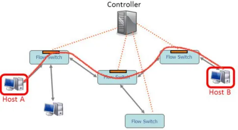
In general, there are three different approaches for the insertion of the flows into the switches OpenFlow-enabled:
1. In the reactive approach, after the first packet arrival to the switch, if there are not matching flow entries in the flow table, the packet is for-warded to the controller. The controller can make some decisions (e.g., drop or forward the packet) and, in case, insert the flow entry into the switch. Then, the next packets related to that specific flow, will be man-aged directly by the switch according to the flow entries.
2. In the proactive mode, before the packets arrival, the controller can proac-tively insert the flow entries into the switches. In that case, when the packets arrive, the switches know how to manage those flows without interactions with the controller.
3. The predictive behavior uses the historical data regarding the network performance to make the adjustment of the routes and flows possible. It follows that the amount of the packets exchanged between the switches and the controller is reduced in the proactive approach. Furthermore, the proac-tive mode makes the “make-before-break” approach possible. In other words,
retrieving information related to the network status is useful to understand what is going on and to prevent a down link by finding a new path.
One other important aspect regards the control plane distribution, which is directly correlated to both the scalability and the availability of the network controller.
2.3.2 Control plane distribution
The distribution of the control plane is not specified by the OpenFlow pro-tocol, as well as the controller-to-controller communication. The controller can be implemented as a single centralized or a distributed server. In case of a distributed solution, different schemes can be implemented (e.g., one main controller and some back-up controllers updated by a hot/cold copy model). However, any type of distribution or redundancy in the control plane can be useful to enforce the availability and scalability of the controller.
The main weaknesses and challenges related to SDNs are explained in Sec-tion 2.4, according to the control models above menSec-tioned.
2.4 SDN weaknesses and challenges
The focus of this section concerns the weaknesses and challenges of dealing with the SDN networks and the OpenFlow protocol. SDN and OpenFlow offer a way to make simple the prototyping, deployment, and management of the network elements. However, we must also take into consideration some inter-esting aspects that can lead the network in an unsafe or unavailable condition [30] [31], as follows:
1. The availability of the controller is the main aspect that is necessary to consider. The tight dependence between the switches and the controller whenever a modification of the rules is necessary, could become a prob-lem. Moreover, if the network design takes into account only one
central-ized controller, it could become a “single point of failure”. A distributed
approach could be implemented to guarantee the availability and avoid a potential undesirable failure. In addition, some redundancy or backup solution could be used for enforcing the robustness.
2. The security is also important. In SDN, the controller is a component with a critical knowledge of the network and this aspect exposes the controller to possible attacks and threats. Additionally, the channels among the con-troller and the switches could be vulnerable. According to the OpenFlow specification, it is possible to use a secure communication by means of the TLS protocol, but its usage depends on the design of the network since it is not required.
3. The consistency of the flow tables is also a potential issue. Since several controllers can manage the same flow tables, for instance, a production hardware controller and some other experimental controllers, it follows that the latter will be the “weakest link in the chain”. Consequently, they could be subject to lower security controls, leading the flow tables in an inconsistent state. An implementation of the flow visor can be suitable for avoiding these potential threats.
4. The scalability of the network also depends on the controller, that po-tentially can become a “bottleneck”. In case too many packets reach the controller, performance issues can occur in the network. It follows that it is important to take into account the distribution of the control plane, presented in Section 2.3.2, for avoiding these undesirable problems. 5. The performance of the network can also be related to the control model
adopted. Since the flow table size is limited, the management of a very large number of flows is still a strong challenge. However, a well de-signed network could reduce performance issues through a proactive approach. In fact, as previously analyzed in Section 2.3.1, the proactive approach reaches better performance than the reactive mode because it limits the amount of messages exchanged among the controller and the switches.
The aspects described above have been taken into consideration by the community researchers and represent the future challenges for the SDNs.
The last section of this chapter presents one of the most widespread con-troller, Floodlight, suitable for dealing with SDNs.
2.5 Floodlight SDN Controller
Many SDN controllers have been developed since the introduction of SDN [18]. However, one of the most widespread OpenFlow controller is Floodlight [32]. Floodlight is a Java-based open source software based on the Beacon con-troller implementation developed at the Stanford University [33], that works with physical and virtual OpenFlow switches. The last release of Floodlight is the version 0.90 and, the following section explains the architecture and the main characteristics of the Floodlight.
2.5.1 Architecture
The Floodlight controller realizes a set of common functionalities to control and inquire an OpenFlow network. As shown in Figure 2.15, the Floodlight ar-chitecture is modular and it is clear the relationship among the controller, the applications built as Java modules compiled with Floodlight, and the applica-tions built over the Floodlight REST API.
Figure 2.15: Floodlight architecture [5]
As depicted in Figure 2.15, the main modules related to the controller core are the following:
1. The Link Discovery is responsible for discovering and maintaining the status of links in the OpenFlow network by means of the Link Layer Dis-covery Protocol (LLDP) and the Broadcast Domain DisDis-covery Protocol (BDDP). Furthermore, the controller periodically commands through the Link Discovery module the switches to flood LLDP and BDDP packets to all their ports. A discovery protocol packet typically contains the Data Path Identifier (DPID) of the sender switch together with the port of the switch which the message originates from. Thus, the controller discovers the direct and indirect connections between the switches. Specifically, a direct link will be established if a LLDP is sent out to one port and the same LLDP is received on another port. It follows that the ports are di-rectly connected. On the opposite side, thanks to the BDDP protocol, it is possible to find indirect connections by means of a flooding approach. In this case, if a BDDP packet is sent out to a port and received on another, a broadcast link is created. It means that there is another layer 2 switch that is not under the control of the controller between these two ports. Further, the controller is also able to verify the connection liveliness with periodical checks.
2. The Topology Manager is designated to maintain the topology informa-tion updated for the controller, as well as to find routes in the network. The topologies are computed by means of the link information retrieved from the Link Discovery service. All the information about the current topology is stored in an immutable data structure called the topology instance. Thus, the controller can determine the shortest path (using the Dijkstra algorithm) from a source switch port to a destination switch port, equipped with the knowledge of the network topology.
3. The Device Manager tracks devices, through the packet-in requests, con-nected to the network and defines the destination device for a new flow. By default, the module uses the MAC address and the VLAN to identify uniquely a device. Furthermore, the Device Manager learns about other important pieces of information such as IP addresses as well permits to know the device attachment points. In that case, if a packet-in is received on a switch, an attachment point will be created for that device. Finally,
this component also ages out attachment points, IPs, and devices them-selves. It exploits the last seen timestamps to keep control of the aging process.
4. The Storage service realizes a storage based on a NoSQL style. It also supports a notification mechanism for changes in the database.
Furthermore, as also depicted in Figure 2.15, some other important appli-cation modules are:
1. The Forwarding component, loaded by default, makes the forwarding of packets between two devices possible, realizing a reactive forwarding approach. It is designed to work in networks that contain both switches OpenFlow-enabled and “regular” switches. However, it works correctly only if loops among groups of switches OpenFlow-enabled and groups of the “regular” switches do not exist. Moreover, the Forwarding module individually handles each packet, and severely limits the performance. 2. The Learning Switch implements a behavior similar to the “regular” L2
learning switch. Thus, the module detects and learns about new devices based on their MAC addresses. When the controller detects a new flow, the Learning Switch identifies the input and the output switches, as well as all other switches on the shortest path between the start and the end point. Once a path has been found, the module installs the appropriate OpenFlow rules for handling the new flows on all participating switches. 3. The Static Flow Entry Pusher allows a user to manually insert flows into an OpenFlow-enabled switch through REST API. Thus, in practice, this module realizes a proactive forwarding approach.
4. The PortDown Reconciliation, when a port or a link goes down, rec-onciles flows across a network. Following a link discovery update, the module discovers and deletes flows directing traffic towards the downed port. Then, it re-evaluates the path that the traffic has to take according to the updated topology. It follows that if this module is not enabled, the persistent traffic continues to be routed to a downed port.

![Figure 2.10: OpenFlow Instruction Set [2]](https://thumb-eu.123doks.com/thumbv2/123dokorg/7461603.101738/41.892.196.697.186.458/figure-openflow-instruction-set.webp)

![Figure 2.14: Packet flow matching [4]](https://thumb-eu.123doks.com/thumbv2/123dokorg/7461603.101738/46.892.225.668.312.649/figure-packet-flow-matching.webp)
![Figure 2.15: Floodlight architecture [5]](https://thumb-eu.123doks.com/thumbv2/123dokorg/7461603.101738/51.892.192.695.624.967/figure-floodlight-architecture.webp)

![Table 4.5: QoS requirements of VoIP, Interactive-Video, and Streaming-Video [11]](https://thumb-eu.123doks.com/thumbv2/123dokorg/7461603.101738/68.892.217.672.475.580/table-qos-requirements-voip-interactive-video-streaming-video.webp)