A ROS-based Workspace Control and
Trajectory Planner for a Seven Degrees
Of Freedom Robotic Arm
Software interfaces for Obstacle Avoidance,
OctoMap Visual Sensing and Target Recognition
features.
Alessandro Santoni
A thesis presented for the degree of
Automation Engineering
Electrical, Electronic and Information Engineering
"Guglielmo Marconi" - DEI
University of Bologna - UniBO
Italy
A ROS-based Workspace Control and Trajectory Planner
for a Seven Degrees Of Freedom Robotic Arm
Software interfaces for Obstacle Avoidance, OctoMap Visual Sensing and
Target Recognition features.
Alessandro Santoni
University of Bologna - UniBO
Abstract
In this Bachelor Thesis I want to provide readers with tools and scripts for the control of a 7DOF manipulator, backed up by some theory of Robotics and Computer Science, in order to better contextualize the work done.
In practice, we will see most common software, and developing environments, used to cope with our task: these include ROS, along with visual simulation by VREP and RVIZ, and an almost "stand-alone" ROS extension called MoveIt!, a very complete program-ming interface for trajectory planning and obstacle avoidance.
As we will better appreciate and understand in the introduction chapter, the capability of detecting collision objects through a camera sensor, and re-plan to the desired end-effector pose, are not enough. In fact, this work is implemented in a more complex system, where recognition of particular objects is needed.
Through a package of ROS and customized scripts, a detailed procedure will be provided on how to distinguish a particular object, retrieve its reference frame with respect to a known one, and then allow navigation to that target.
Together with technical details, the aim is also to report working scripts and a specific appendix (A) you can refer to, if desiring to put things together.
Keywords : SHERPA EU Project, 7DOF Manipulator, ROS, MoveIt!, OctoMap, Obsta-cle Avoidance, Target Recognition
A ROS-based Workspace Control and Trajectory Planner
for a Seven Degrees Of Freedom Robotic Arm
Software interfaces for Obstacle Avoidance, OctoMap Visual Sensing and
Target Recognition features.
Alessandro Santoni
University of Bologna - UniBO
Abstract (Italiano)
In questo lavoro di tesi verranno forniti tutti gli strumenti, e i codici funzionanti, per il controllo di un manipolatore a 7 DOF, accompagnati da nozioni teoriche di Fondamenti di Robotica ed Informatica.
Analizzeremo i programmi e gli ambienti di sviluppo comunemente usati in questo am-bito, per ottenere un "Workspace Control" del robot in questione : passeremo da ROS, con simulazione tramite VREP e RViz, fino a una "estensione" di ROS chiamata MoveIt!, un’ interfaccia molto completa per il trajectory planning ed Obstacle Avoidance.
Tuttavia, sarà chiaro fin dal capitolo introduttivo, che non sarà sufficiente essere in grado di modellizzare l’ambiente di collisione nei paraggi del robot ed evitare di conseguenza gli ostacoli. Dovremmo infatti efficacemente riconoscere degli oggetti specifici.
Tramite personalizzazione di un pacchetto ROS, verrà mostrata una procedura dettagliata su come distinguere oggetti particolari, recuperare il loro reference frame rispetto ad uno già noto, e quindi permettere la navigazione verso questo obiettivo.
Oltre ai dettagli tecnici, l’appendice A, allegata alla tesi, servirà da guida per chiunque volesse scaricare gli scripts e i files di questa tesi, e riprodurre le applicazioni riportate.
Keywords : SHERPA EU Project, 7DOF Manipulator, ROS, MoveIt!, OctoMap, Obsta-cle Avoidance, Target Recognition
Contents
1 Thesis Introduction 13
1.1 Sherpa Project . . . 13
1.2 ROS - Robot Operating System . . . 15
1.3 7DOFs Manipulator Specifics . . . 16
2 Basics of Control Theory and Robotics 17 2.1 Structure of a Manipulator . . . 17
2.2 Physical Interpretation . . . 18
2.3 Inverse Kinematics . . . 18
3 VREP - Virtual Robot Experimentation Platform 21 3.1 General Configuration . . . 21
3.2 Interfacing VREP and ROS . . . 22
3.3 Limits of VREP . . . 24
4 MoveIt! Interface 25 4.1 MoveIt! Architecture . . . 25
4.1.1 Robot Model . . . 26
4.1.2 Robot Feedback and Controllers . . . 26
4.1.3 3D Perception . . . 26
4.1.4 Moveit! User Interface . . . 27
4.2 Setup for the SHERPA Arm . . . 27
4.2.1 MoveIt! Setup . . . 27
4.2.2 RVIZ Setup . . . 30
4.3 Scripts and Applications in MoveIt! . . . 31
4.3.1 Joint-Space Goal . . . 31
4.3.2 End-Effector Pose with Obstacles . . . 33
5 Interfacing a Kinetic Sensor with our System 39 5.1 Camera Sensor Setup . . . 39
5.1.1 Kinect Parameters . . . 40
5.1.2 PointCloud for RViz . . . 40
5.1.3 OctoMap Updater . . . 40
5.1.4 The Launch File . . . 42
5.2 Applications and scripts . . . 44
6 Visual Detection and Identification 47 6.1 Find Object Package . . . 47
CONTENTS
6.2.1 Pattern Detection . . . 48
6.2.2 Scripts and Files . . . 48
6.3 Testing Object Detection . . . 56
6.3.1 Retrieval of the UAV’s Reference Frame . . . 56
6.3.2 Gathering up Data in the same RViz instance . . . 56
7 Conclusion 59
Appendices 61
A Making it Work 63
B Code License 67
List of Figures
1.1 The senseSoar, fixed-wing UAV . . . 13
1.2 Drone and Rover Representations . . . 14
1.3 ROS concepts . . . 15
1.4 Rover Manipulator . . . 16
1.5 Gripper of the Arm . . . 16
2.1 SHERPA Rover Arm . . . 17
3.1 URDF model Configuration in VREP . . . 21
3.2 RQT Graph in VREP - ROS communication . . . 24
4.1 MoveIt! System Architecture . . . 25
4.2 Communication between move-group and Joint States . . . 26
4.3 Arm’s TF tree in RVIZ . . . 30
4.4 Display Planned Path topic . . . 30
4.5 Obstacle Avoidance . . . 36
5.1 ASUS Xtion PRO Camera . . . 39
5.2 OctoMap Updater on RViz . . . 41
5.3 Obstacle Avoidance with Camera Sensor Configuration . . . 46
6.1 Terminal Output, Object Recognition . . . 54
6.2 Obj Recognition, TF tree retrieved . . . 56
Listings
3.1 VREP subscriber to /setJointPosition ROS topic - (LUA) . . . 22
3.2 ROS publisher to VREP - (Python) . . . 23
4.1 Mimic function on the elbow . . . 27
4.2 Jnt4 URDF constraints . . . 28
4.3 MoveIt! Kinematic Solver . . . 28
4.4 SHERPA arm SRDF model . . . 29
4.5 Joint Space Goal - (C++) . . . 31
4.6 Obstacle Avoidance given End-Eff desired pose - (C++) . . . 33
5.1 Sensor Manager file . . . 40
5.2 Kinect Sensor yaml file . . . 41
5.3 RViz simulation with OctoMap Updater - (Launch file) . . . 42
5.4 Obstacle avoidance with a configured kinetic sensor - (C++) . . . 44
5.5 Obstacle avoidance for an End-Effector setpoint - (Launch file) . . . 46
6.1 Object Detection - (C++) . . . 48
6.2 Retrieval of Object’s Frame - (C++) . . . 52
Chapter 1
Thesis Introduction
1.1
Sherpa Project
The work presented in this document has to be contextualized in a more wide project the University of Bologna, along with other European partners, is involved in: the Sherpa Project [1]. This programme, started in 2013, aims at building a "fleet" of robots, either aerial and grounded, able to enhance human rescue operations in hostile environments, such as the alpine one. The many platforms, having the purpose to help humans in these situations, are programmed to be collaborative, autonomous and self-aware.
In few words, every robot knows where it is in the space relatively to the "human leader", its battery-life left, as well as positions and messages from the other units. Once a trigger-ing command is sent, in this case represented by the effective localization of the stricken area, every platform knows how to behave and act, without any need of further specifica-tions by the operators.
Achieving this level of automation, via advanced controls and cognitive capabilities of the robots, allows the system to require minimum supervision by the human team; In fact, this project considers the rescuer as the "busy genius", meaning that is the one really in charge of the operation, although in most cases not able to manage these many devices. Here lies the importance of a smart implementation in terms of collaborative strategies towards the achievement of a common goal among both the group of robots, and the rescuers.
Figure 1.1: The senseSoar, fixed-wing UAV
This group of devices includes a fixed-wing UAV and an RMax rotary-wing, with cutting-edge technology for vision and detection of targets, however, due to their struc-ture, constrained to fly at high altitudes. It includes also multiple quad-rotors UAVs,
1.1. SHERPA PROJECT
characterized by agility and ability to reach most inhospitable places, although having as a main drawback a short life in terms of batteries. Finally, this "robotic-team" includes a ground rover with a multi-purpose arm mounted on it, that carries the main computational unit, has high level of autonomy and a long battery life.
Hereafter some illustrations are reported.
(a) Representation of rescuer and ground rover
(b) The quad-copter UAV
Figure 1.2: Drone and Rover Representations
This work is centred on the ground robot, which is the one physically following the operator, able to plan its own path behind him, carrying the computational unit and the drones that are going to be detached once around the critical zone. As previously said, in order to set a certain level of autonomy, it has to be able to process gestural as well as vocal commands given by its leader. This stand-alone capability includes also the management and elaboration of the data flow coming from the devices, that use the Sherpa-BOX as a central "common brain"; this is what practically makes the system so self-supporting. In particular, I had the opportunity to work on the 7 DOFs rover arm, which has been designed to pick up landed copters and place them in their respective slots on the rover. The main features we are going to add to the system are: work-space control and motion planning, given a desired end effector pose, an elaboration of joint trajectories takes place to reach the final desired point; communication between camera data and planning core, in order to detect collision objects, avoid obstacles and keep refreshing the always chang-ing surroundchang-ing environment; Eventually, recognize the landed quad-copter, retrieve its reference frame relative to the ground rover, essentially giving to it a target for the navi-gation, until the UAV is reachable by the arm itself.
CHAPTER 1. THESIS INTRODUCTION
1.2
ROS - Robot Operating System
The Robot Operating System [2], best known as ROS, is a very powerful collection of libraries and tools aimed at configuring and writing robots’ software. In this work, ROS Indigo, LTS version, has been installed on Ubuntu Trusty 14.
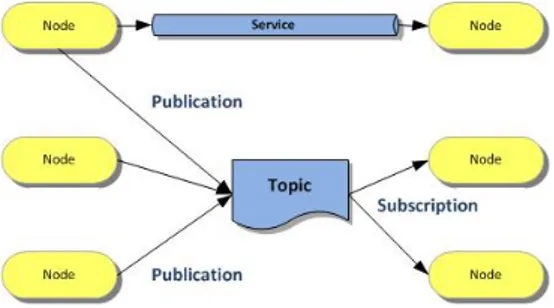
Figure 1.3: ROS concepts The reason why this operating system is
spreading more and more, is because of its in-novative way of describing and handling the many parts that are going to characterize the final behaviour of the intended robot: indus-trial manipulators, drones as well as other mo-bile platforms up to highly complex humanoids with state-of-the-art AI capabilities. In prac-tice, this result has been achieved with a mod-ular programming method, stimulating collab-orative work. As a matter of fact, ROS is or-ganized mainly in nodes, topics and messages (plus other many elements for the moment I
avoid telling for sake of explanation). What is being done, is that a programmer builds a node, a mini-core of the overall structured software, that adds one or more particular capabilities and is able to send and receive messages through channels called topics. To keep communication organized, a master node handles the most basic functions such as subscriptions and publications on topics.
In broad terms, our particular application requires to read mechanical values from the arm, to elaborate suitable trajectories, to collect data from an RGB camera and eventually to detect a specific object. All of these will be the main cores of the software, and they will exchange information or services thanks to proper messages that the sender is able to write and the listener is able to receive and process.
Due to the high readability of the nodes and topics graphs that we can extrapolate from ROS, I will make use of them to show in a detailed manner how the pieces work together, scope and features of each software block and the way in which a simulating engine fits in the scheme, to give us the possibility to experiment and test functionalities of the intro-duced "code-brick".
Finally, a GUI will be an additional node that listens to topics such as "joints trajectories" and position of "collision objects", and graphically helps us in appreciating the actual underneath software implementation.
1.3. 7DOFS MANIPULATOR SPECIFICS
1.3
7DOFs Manipulator Specifics
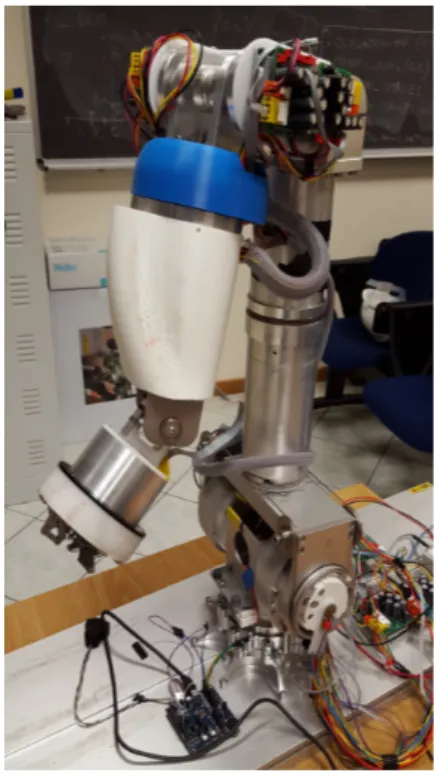
Entering in the technicalities, a description of the arm must be done. Even though low-level implementation is not our final purpose, it clearly is the starting point of a workspace control. Indeed, physical components such as actuators, regulators and wiring (fieldbuses, power cables), are the constraints we have to keep into account in planning the motion for our end-effector.
Figure 1.4: Rover Manipulator
The mechanical structure is composed by a 3DOFs shoulder, a single DOF elbow and a 3DOFs wrist. In particular, the elbow actually contains two joints at a distance of about 15cm; Even if the DOF is only one, because the two revolute connections are dependent with a fixed gear ratio 1 : 1 , this lit-tle separation allows reaching particular poses and, when needed, rest in a folded-arm position. The end-effector has three fingers, dependent on each other since actuated with a single motor.
This design, allows determination of multiple solu-tions in the joint-space for gripper poses in the reach of the arm; Indeed, it is redundant (DOF s > 6) leaving some margin for particular motion plan-ning applications, such as obstacle avoidance and replanning capability, when the desired pose is not reached due to an obstacle, or not reached in the most suitable way.
Figure 1.5: Gripper of the Arm Communication is managed through CAN
in-terface and proper ROS configuration. More in depth, what we are really interested in, is the method the arm uses to process a given trajectory, namely, how it handles joint-states and joint-controllers commands. Each mo-tor is equipped with an absolute plus an in-cremental encoder in order to accurately per-form our motion requests; The incremental one is directly readable from the velocity regu-lators, however, without an absolute encoder it wouldn’t know its exact position with re-spect to the TF tree of the arm’s kinematic chain.
Knowing the very basics of actuation and commu-nication between controllers and arm, we can enter more in detail concerning the proper ROS program-ming of the tasks we want it to accomplish.
Chapter 2
Basics of Control Theory and Robotics
2.1
Structure of a Manipulator
Robot manipulators, from a physical point of view, are intended as a set of interconnected link and joints, that, strongly depending on their design, are able to perform certain tasks rather than others. For example, we may distinguish between manipulators that are re-dundant or not, parallel or serial structures, or just characterize robotic arms depending on the kind of joints used in their construction.
Figure 2.1: SHERPA Rover Arm
The SHERPA Rover Arm has the following charac-teristics:
• It is a serial chain, meaning that, moving from the end-effector down to the base, higher torques mo-tors have to be adopted, due to the fact that in a serial structure each joint must support, and allow the motion, of the following links.
• It is only formed by 1 DOF joints, that are way simpler to manage in terms of computational power needed and mathematical modelling, yet not introducing any particular constraint on the trajectories and motions we can achieve with that arm.
• In particular, it only consists of revolute joints. These kinds of manipulators are for this reason called anthropomorphic, recalling their structural similarity with human arms.
• Eventually, it is said to be redundant, having di-mension of the joint-space (7DOF) greater than the dimension of the work-space (imposed by our physical world and equal to 6).
2.2. PHYSICAL INTERPRETATION
2.2
Physical Interpretation
Motion Control for such a robot is all about properly mapping Jointspace and Workspace, so that either direct and inverse kinematics can be carried out.
We will see that our Software Tools are actually able to extrapolate such a map from the model of our manipulator, however, for the sake of completeness, let’s go a bit through these mathematical and geometric concepts.
Joint Space According to the number of independently actuated joints, we would define a vector of joint values :
q = [θ1, θ2, · · · , θ7] so that q ∈ IR7
In our application it has dimension 7, coincident with the number of DOFs of the arm, and contains angles due to the fact that it has an anthropomorphic structure.
In order to perform tasks with it, we can just act at the "low-level" that is the joint-space; Indeed, giving values to the vector q (that is give setpoints to each joint) we would define a position for our end-effector.
Work Space However, the most interesting (and most frequent) operation we want such an arm to carry out, is to elaborate a proper set of joint values in order to place the end-effector in a desired point in space: in our case, even with a certain orientation.
With the word Workspace we indicate the set of possible configurations the end-effector may assume in our space that, for a rigid body, has dimension 6.
Hence, a vector x would contain 3 position parameters (e.g. Cartesian coordinates) and 3 orientation parameters (e.g. Euler angles):
x = [px, py, pz, φ, θ, ψ] where x ∈ IR6
Map Workspace ↔ Jointspace At this point we want to find a mapping between this two spaces. In other words, a function f that holds :
f : IR7 → IR6 , x = f (q)
Such a function would bond together the end-effector and the joint angles, with a mathematical map.
2.3
Inverse Kinematics
The function f above, is in charge of the so-called "Direct Kinematics", that is the prob-lem of defining the end-effector configuration-vector x, once known the joint parameters q.
However, as pointed out before, in this thesis we face the task of solving Inverse Kine-matics (IK), that is mapping :
CHAPTER 2. BASICS OF CONTROL THEORY AND ROBOTICS
Both maps are obviously non-linear functions. To solve the Inverse Kinematic prob-lem, that is finding proper joint values known a desired x, we would definitely prefer a linear relationship.
The Jacobian would be our "solving engine" exactly for this reason.
Jacobian Matrix If the functions above represent a "position mapping", we will the define through the Jacobian, the derivative of that map, that would be a relationship at the "velocity level", from a physical point of view.
We define the Jacobian Matrix as follows:
J(q)
=
∂f (q) ∂q=
∂f1 ∂q1 ∂f1 ∂q2· · ·
∂f1 ∂q7...
...
. . .
...
∂f6 ∂q1 ∂f6 ∂q2· · ·
∂f6 ∂q7
By exploiting this matrix we can now define :
d dtx =
d
dtf (q) ⇒ x = J(q) · ˙q˙
This equation is no more non-linear. In fact, now velocities of the joints and end-effector’s linear and angular velocities are linearly correlated, thanks to the Jacobian Ma-trix J(q).
Since it goes IR7 → IR6
, then it would be not square, hence an inverse J−1(q) shouldn’t exist.
For this purpose, our solving engines will instead make use of the pseudo-inverse that, as an additional advantage, are mathematically proven to give the "best solution": techni-cally speaking, the solution with the minimum norm.
Given the vector ˙x and called the pseudo-inverse with J+, we get: ˙
q = J+· ˙x , the solution having minimum k ˙q sk
The fact that with this method we have the "optimal solution" is because, having a redundant manipulator, whenever a solution for the inverse kinematics exists, then we actually will have infinite solutions.
This is possible because we still have 1 dimension, that is 1 DOF (in practice nothing but 1 joint variable) that we may still exploit to change the arm configuration but not the gripper pose.
Having such a possibility will be key in our obstacle avoidance tasks : in these cases we want the arm to re-plan its trajectory to the "goal pose"; If the solution had been unique, it would have just been impossible to do so.
Singularities At the moment, we just overcame the problem of finding the inverse of a non-square matrix by using the pseudo-inverse.
Still, if the matrix above wouldn’t be maximum rank, the procedure in the last equation, that is deriving ˙q from ˙x, would not hold.
Due to the fact that J(q) is built with functions of the joints, there would exist particular arm’s configuration that do not make rank(J) = min(6, 7) = 6.
Whenever the Jacobian Matrix has not maximum rank we are in a Singular Configuration that, from a physical point of view, is translated in loosing one or more Degrees of Free-dom.
2.3. INVERSE KINEMATICS
These configurations are coincident, for example, with the alignment of 2 (or more) dif-ferent joints. In fact, in that exact instant of time, and for an infinitesimal displacement dx, the two joints that are independently actuated, would rather just define a motion (ro-tating motion due to the revolute joints in our case) around coincident axes.
In our application, we will take particular care in avoiding Boundary singularities (done via not working at the edge of the arm’s reaching space) and Internal singularities, more difficult to detect and avoid (still doable via our software tools).
Chapter 3
VREP - Virtual Robot Experimentation
Platform
3.1
General Configuration
Figure 3.1: URDF model Configuration in VREP VREP [3] is a simulation
plat-form developed by Coppelia Robotics. It exploits LUA lan-guage for its API functions and makes use of threaded or non threaded scripts to manage be-haviour of the mechanical parts under experimentation. The dif-ference between threaded and non-threaded is that the last one is nothing but a script elsewhere known as a function, that means, executes the code and returns control; Moreover, it is executed in a cascade way, so we are going to respect the TF tree hierarchy of our system. It has to be preferred,
whenever possible, to a threaded script, that may induce in infinite loops and waste com-putational power.
VREP has the capability to import URDF models, that we use to represent our arm in vir-tual environments. Once uploaded the respective meshes, the program recognizes joints, links, the overall children-parents structure and is ready for simulations, using powerful physics engines (I have chosen BULLET). First of all, to make the system able to with-stand its own weight, we set the joints’ actuators in torque/force mode with suitable max-imum torque [N · m] and a simple PID controller on position (since not looking for high performances in this part of the configuration, a Proportional controller with Kp = 0.1
3.2. INTERFACING VREP AND ROS
3.2
Interfacing VREP and ROS
This simulation environment has the intrinsic capability of connecting with ROS. In fact, specific libraries (such aslibv_repExtRos.so) add particular API functions for the in-tercommunication between them. On the other side, ROS is able to manage VREP as a node and interact with it through topics.
Hereafter, I want to show a simple publisher and subscriber between these two pro-grammes; A node-topics graph will be reported as well.
At VREP’s side I want to enable subscription to ROS topic /setJointPosition that will broadcast float64 messages containing position setpoints for a joint. The simulation
envi-ronment will be able to catch those messages through the commandsimros_strmcmd_set_joint_target_position. if ( sim_call_type == sim_childscriptcall_initialization ) then
-- testing if roscore is on local moduleName =0
local moduleVersion =0 local index =0
local pluginNotFound = true
while moduleName do
moduleName , moduleVersion = simGetModuleName ( index )
if ( moduleName =='Ros ') then pluginNotFound = false end
index = index +1 end
if ( pluginNotFound ) then
-- Display an error message if the plugin was not found : simDisplayDialog ('Error ','ROS plugin was not found .&&
nSimulation will not run properly ',sim_dlgstyle_ok ,false ,nil ,{0.8 ,0 ,0 ,0 ,0 ,0} ,{0.5 ,0 ,0 ,1 ,1 ,1})
else
-- handle of the elbow joint we want to control elbowHandle = simGetObjectHandle ('ElbowD_1 ')
subscriberID = simExtROS_enableSubscriber ('/ setJointPosition ', 1, simros_strmcmd_set_joint_target_position , elbowHandle , -1, ''
)
end end
Listing 3.1: VREP subscriber to /setJointPosition ROS topic - (LUA)
On the counterpart, ROS must create a node publishing those desired positions on the common chosen topic; In practice, we will send cyclic positions around the rotation axis of the revolute joint. For this application we will use Python because, to experiment a little bit, we are going to change often this setpoints, and a .py script doesn’t need to be recompiled through commandlinecatkin_make each time a variation in the code occurs. Note : Remember to make the script executable through sudo chmod<users> +x <file.py> command from terminal.
CHAPTER 3. VREP - VIRTUAL ROBOT EXPERIMENTATION PLATFORM
#!/ usr / bin / env python
# joint_position_publisher .py
import rospy
from std_msgs . msg import Float64
def joint_position_publisher ():
pub = rospy . Publisher (' setJointPosition ', Float64 , queue_size =10) rospy . init_node (' joint_position_publisher ', anonymous = True )
# anonymous gives unique name to nodes in case of an homonymy
rate = rospy . Rate (1) # once per second , 1Hz # init variables
count =4 #we start from a middle position
sign =1 # used to go back and forth with the arm
desired_joint_position = 0
while not rospy . is_shutdown ():
desired_joint_position += sign *(3.1415/12) count += 1
if ( count %6) == 1 : sign = sign *( -1)
pub . publish ( desired_joint_position )
rate . sleep () # keeps the desired 1Hz transmission frequency
if __name__ == '__main__ ':
try:
joint_position_publisher ()
except rospy . ROSInterruptException :
pass
Listing 3.2: ROS publisher to VREP - (Python)
To launch the application, once built and compiled a proper catkin_pkg with relative CMakeLists.txt and Package.xml, we want to run the publishing node and then start the simulation. The following steps will guide us into it. From terminal’s commandline execute:
• Launch the master :roscore
• rosrun set_joint_position_vrep joint_position_publisher.py • Monitor topic messages withrostopic echo /setJointPosition • Open VREP scene previously created with the non-thread child script above • Run the simulation either from VREP GUI or via ROS service :rosservice call
3.3. LIMITS OF VREP
Clearly, depending on the joint’s constraints, the controller used and the torque of the motor, the achieved result varies. Remember also to set the base link "not dynamic", indeed, in the real case, it is fixed on the rover base.
As we said, through command rosrun rqt_graph rqt_graph we can get a map of nodes and topics in our system. This time it turns out to be a very simple one, however, we will have the opportunity to appreciate this tool later on in more complex applications of our project.
Our scheme is :
Figure 3.2: RQT Graph in VREP - ROS communication
3.3
Limits of VREP
What we achieved is the control of a single joint, however, it’s easy to understand, that the trajectory of a kinematic chain is something more complex. By trajectory (that we will physically define and describe in the next section) we intend a stream, namely an array float64[], containing velocities and accelerations of the specific joints in multiple instants of time : as a result, we obtain the trajectory in terms of positions.
VREP, despite being very accurate and graphically elegant, would require unpacking and assignment for each trajectory stream, to every single joint. That’s because, through ROS, we elaborate JointTrajectory.msg types that VREP is not yet able to process. The final choice as a Graphical Simulation Engine will be RVIZ (ROS-Visualization) environment.
Chapter 4
MoveIt! Interface
4.1
MoveIt! Architecture
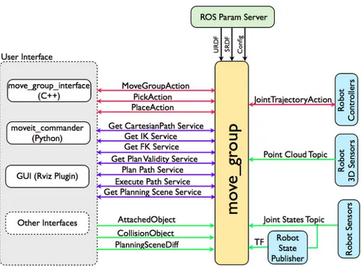
The software MoveIt! [4] will be the central core of this thesis application, since gives us tools that span from motion planning to 3D perception. The most fundamental point, is that it is naturally linkable with ROS through methods explained in the Introduction chapter (nodes, topics...).
MoveIt! has been originally developed by Willow Garage, becoming very soon of public domain thanks to its open-source license. It has a very powerful system architecture, is able to process scripts in either Python or C++ and it’s readily possible to interface it with RVIZ.
4.1. MOVEIT! ARCHITECTURE
From the Fig. 4.1 it’s very easy to understand why and how this software will be pivotal in our implementation.
4.1.1
Robot Model
In the very top section of the scheme, we notice that the node move_group reads 3 pa-rameters : they represent the model of our robot, in a format that this software is able to understand. The URDF (Unified Robot Description Format) lists all the details of the kinematic chain (in our application with the rover arm), links and joints, TF tree hier-archy and whichever constraint we may set (effort, position, velocity, acceleration). Its correspondent SRDF (Semantic Robot Description Format) is generated after the first configuration is completed, and contains the most useful information on our robot: joint limits, pre-defined positions (I defined an home position, for example), planning groups, end-effector structure and finally a list of links that are always or never in collision, in order to slim computations.
4.1.2
Robot Feedback and Controllers
From the robot sensors, the central "high-level" node always keeps track of the overall structure’s position and orientation. Indeed the TF tree is refreshed at high-frequencies to cope with dynamic environments, with obstacles spawning in the arm’s workspace, and to allow planning around them, respecting chain’s design limits and avoiding self-collisions. Once a trajectory is successfully planned, we may execute it. The Robot Controllers are interfaced with the move_group node to perform this task. By using rqt_plot, we can see that they are actually transmitting commands for the motion of our arm.
Figure 4.2: Communication between move-group and Joint States
4.1.3
3D Perception
Another very useful capability of this MoveIt! structure is the one of reading real time camera sensors’ data through point cloud topics. We will make use of this kind of com-munication when configuring a kinect sensor for the arm. Essentially, the point cloud updates the Occupancy Map in the World Geometry of the robot; Thus, is possible to make a direct translation from depth and RGB data into collision objects. At this point, we will be able either to plan around them and to keep "listening" to the point cloud topic for updates of the surrounding environment.
CHAPTER 4. MOVEIT! INTERFACE
4.1.4
Moveit! User Interface
The way in which a programmer can interact with this Moveit! architecture is basically described by the topics, actions or messages we can exploit to communicate with the move_group node. There exist particular actions for a pick and place application, the user may define collision object by script and place them in the map or attached to the robot: in the latter case, the planner keeps that object into account in elaborating trajectories. Moreover, we can exchange information on Inverse Kinematics calculations, generated paths (planned and/or executed) and planning scene structures.
Note : A GUI (we choose RVIZ, as already said) has to be like a simple listener to the TF tree, planning scene and path generation topics, so that it can graphically represent what the move_group node has processed from our ROS script request.
4.2
Setup for the SHERPA Arm
4.2.1
MoveIt! Setup
The linkage between MoveIt! and the real robot, we said, is the URDF. Actually, due to some peculiarities in our model, a couple of modifications have to be done.
1DOF elbow The elbow of our arm has one degree of freedom, however, it is built by 2 revolute joints. In general, they should add 2DOF but in this case they are linearly dependent with a fixed gear ratio. This value is 1 : 1 so we want to insert in the model a mimic function, with multiplier 1, betweenJnt4 and Jnt4_2. Moveit! will be able to read this information and plan accordingly.
<joint
name =" Jnt4_2 "
type =" continuous "> <mimic
joint =" Jnt4 " />
Listing 4.1: Mimic function on the elbow
In addition, from the planner point of view, the jointJnt4_2 is seen as non actuated; To explain it better, in the real case as well as in the model, it follows movement ofJnt4 then MoveIt! must not take it into account in motion planning.
To implement this feature,Jnt4_2 is set to passive.
One last consideration is for the elbow constraints. Once determined in Laboratory the range of positions it can assume due to its wiring, we must take action in setting joint limits.
Note that the planner will take actions itself for position limits when auto-collision may occur, but in this case we have an external constraints due only to the cables passing through the arm. The planner wouldn’t know of these connections, so we need to "im-pose" them in the URDF model. Code is reported in the following page.
4.2. SETUP FOR THE SHERPA ARM <joint name =" Jnt4 " type =" revolute "> <limit lower =" 0.0 " upper =" 1.509 " />
Listing 4.2: Jnt4 URDF constraints
Note : "Joint Type" is now revolute. This is the kind of joint that allows us to set position limits (as well as velocity or effort ones). With type "continuous" we are not setting any external constraint. Planning would be limited to avoiding obstalces and self-collisions. Kinematic Solver As explained in Chapter 2.3, we are going to solve our IK problems with the Jacobian. That’s because we saw that it makes possible to have a linear relation-ship between Work-space and Joint-space velocities.
Upon completion of the initial set-up, we will have a configuration file, namedkinematics.yaml, containing the following information :
arm:
kinematics_solver: kdl_kinematics_plugin / KDLKinematicsPlugin kinematics_solver_search_resolution: 0.005
kinematics_solver_timeout: 0.005 kinematics_solver_attempts: 3
Listing 4.3: MoveIt! Kinematic Solver
Let’s analyse the single parameters :
• The kinematic_solver chosen is the one provided by MoveIt! that works with the jacobian principle
• The value for search_resolution is the resolution the solver uses to search over the redundant space. In our application this is very important for obstacle avoidance, hence an accurate resolution is needed.
• With timeout we mean the maximum time allotted to solve the IK problem once started a certain solution cycle.
• The "complementary" parameter to the one above would be the attempts. With this number we specify how many solution cycles we want the solver to go through. The values given to those entries above have proven to be a good trade-off between computational weight and speed in the determination of a solution.
Semantic Robot Description Format - SRDF Once brought to an end the initial con-figuration of our robotic platform in MoveIt!, a very useful SRDF file will be created, containing the most important information on the arm. MoveIt! will deal just with it, from now on.
CHAPTER 4. MOVEIT! INTERFACE
<robot name =" SHERPA_ARM_1 .4">
<!-- GROUPS: Representation of a set of joints and links . This can be useful to specify the DOFs considered in planning tasks , defining arms , end effectors , etc -->
<group name =" arm ">
<joint name =" virtual_joint "/> <joint name =" Jnt1 "/> <joint name =" Jnt2 "/> <joint name =" Jnt3 "/> <joint name =" Jnt4 "/> <joint name =" Jnt4_2 "/> <joint name =" Jnt5 "/> <joint name =" Jnt6 "/> <joint name =" Jnt7 "/> </ group >
<!--GROUP STATES: Purpose: Define a named state for a particular group , in terms of joints values . -->
< group_state name =" home " group =" arm "> <joint name =" Jnt1 " value =" 0.0353 "/> <joint name =" Jnt2 " value =" 0.0353 "/> <joint name =" Jnt3 " value =" 0.2118 "/> <joint name =" Jnt4 " value =" 0.15 "/> <joint name =" Jnt4_2 " value =" 0.15 "/> <joint name =" Jnt5 " value =" 0.0353 "/> <joint name =" Jnt6 " value =" 0.1765 "/> <joint name =" Jnt7 " value =" 0.2118 "/> </ group_state >
<!--END EFFECTOR: Purpose: Represent information about an end effector . -->
< end_effector name =" end_eff " parent_link =" Gripper " group =" arm "/> <!-- VIRTUAL JOINT: Purpose: this element defines a virtual joint
between a robot link and an external frame of reference ( considered fixed with respect to the robot ) we need this joint to fix the arm to the simulation environment map in RVIZ . --> < virtual_joint name =" virtual_joint " type =" fixed " parent_frame ="
odom_combined " child_link =" base_link "/>
<!-- PASSIVE JOINT: Purpose: this statement is used to mark joints that are not actuated . Jnt4_2 mimics Jnt4 , hence ... -->
< passive_joint name =" Jnt4_2 "/>
<!--For the sake of easing readability , I avoid reporting all the list of joints always or never in collision , that , as said in the previous chapter , are an indication to the motion planner to
save computational power and time --> </ robot >
Listing 4.4: SHERPA arm SRDF model
Let’s now move to the simulation environment RVIZ and understand more in detail how we can use our model there.
4.2. SETUP FOR THE SHERPA ARM
4.2.2
RVIZ Setup
Figure 4.3: Arm’s TF tree in RVIZ
RVIZ [5] is a powerful GUI used to have graph-ical feedback of our ROS - MoveIt! applica-tions.
It listens to various topics in order to vi-sualize results coming from motion planning algorithms. The most basic ones are the topics shown in Fig: 4.2, that allow send-ing commands as well as retrieve informa-tion on the overall structure of the robot, that means, kinematic chain parent-children rela-tionships and reference frames from all the rigid bodies. This last one is the TF tree, that RVIZ shows in the Fig:4.3 here on the side.
Eventually, the trajectory is reported by
MoveIt! through a topic readily
un-derstandable by RVIZ, that is named "/move_group/display_planned_path". It is transmitted as a series of "waypoints" (in
Fig : 4.4 are shown only some points to keep the image quickly to glance at) that are veloc-ity and acceleration values for some given intervals of time measured in [ns].
From the figure we can appreciate the ability of this simulation engine to read Float64[] arrays, that were the inability and limit of VREP environment.
In practice, they are transmitted via a custom MoveIt! message called moveit_msgs::DisplayTrajectory.
Figure 4.4: Display Planned Path topic
Other two fundamental aspects of RVIZ have to be cited : The OMPL and the Oc-toMap.
The former is the acronym of Open Motion Planning Library [6] , a collection of algo-rithms used in planning: in other terms, is the main tool in our arm obstacle avoidance feature, that may even require multiple solving attempts, through the kinematic solver we chose and explained in a couple of paragraphs back.
CHAPTER 4. MOVEIT! INTERFACE
we will need to superpose to the "world" of RVIZ, what our kinetic sensor will be able to detect in following chapters’ applications. This is done via this OctoMap [7] service that places collision objects in the space according to the camera data-stream.
In the next pages we will effectively exploit this functionality.
4.3
Scripts and Applications in MoveIt!
In this section I report the actual work done concerning the use of MoveIt! on the rover arm, still without camera kinect sensor. I will bring two examples : a simple joint space controlsending setpoints, testing if the communication through robot state and joint pub-lisher works fine; And an obstacle avoidance piece of software, where at first I set an end-effector desired pose, than I insert collision objects in its trajectory, and the arm smartly re-plans its path to the same point in space (with the same orientation too) as before.
4.3.1
Joint-Space Goal
The code is reported hereafter :# include <moveit / move_group_interface / move_group .h>
# include <moveit / planning_scene_interface / planning_scene_interface . h>
# include < moveit_msgs / DisplayRobotState .h>
# include < moveit_msgs / DisplayTrajectory .h>
# include < moveit_msgs / AttachedCollisionObject .h>
# include < moveit_msgs / CollisionObject .h>
int main (int argc , char ** argv ) {
ros :: init (argc , argv , " rover_arm_joint_space_goal "); ros :: NodeHandle node_handle ;
ros :: AsyncSpinner spinner (1) ; spinner . start ();
// wait some time to load RVIZ
sleep (15.0) ;
moveit :: planning_interface :: MoveGroup group (" arm "); moveit :: planning_interface :: PlanningSceneInterface planning_scene_interface ;
// publisher for RVIZ
ros :: Publisher display_publisher = node_handle . advertise < moveit_msgs :: DisplayTrajectory >("/ move_group /
display_planned_path ", 1, true);
moveit_msgs :: DisplayTrajectory display_trajectory ; ROS_INFO (" Reference frame for the robot : %s", group . getPlanningFrame (). c_str ());
4.3. SCRIPTS AND APPLICATIONS IN MOVEIT!
ROS_INFO (" Ref . frame for the End Effector : %s", group . getEndEffectorLink (). c_str ());
// planning to a joint space GOAL
std :: vector <double> group_variable_values ;
//I'm writing in the new array defined above the current values of the robot 's joints
group . getCurrentState () -> copyJointGroupPositions ( group . getCurrentState () -> getRobotModel () -> getJointModelGroup ( group . getName ()), group_variable_values );
// now I change some values
group_variable_values [1] = -0.8; group_variable_values [2] = 1.2; group_variable_values [3] = 0.7; group_variable_values [6] = -1.2;
group . setJointValueTarget ( group_variable_values );
// Plan with the new setpoints in group_variable_values []
moveit :: planning_interface :: MoveGroup :: Plan my_plan ;
bool success = group . plan ( my_plan );
ROS_INFO (" Visualizing plan ( joint space goal ... %s)", success ?
"":"== FAILED ==");
sleep (10.0) ; // give time to RVIZ to plan
if( success ) // making use of moveit_msgs :: DisplayTrajectory to display trajectory
{
ROS_INFO (" let 's see it once again ");
display_trajectory . trajectory_start = my_plan . start_state_ ; display_trajectory . trajectory . push_back ( my_plan . trajectory_ );
display_publisher . publish ( display_trajectory ); sleep (10.0) ;
}
ros :: shutdown ();
return 0; }
Listing 4.5: Joint Space Goal - (C++)
Breaking down the code :
• Definition of a ROS noderover_arm_joint_space_goal and its handle.
• Instantiation of the planning group "arm", registered in the SRDF, and of a planning-scene object.
• A proper messagemoveit_msgs::DisplayTrajectory is the mean of communi-cation between MoveIt! and RViz. The publisher broadcasts this kind of messages to the topic /move_group/display_planned_path, of which our simulator is a subscriber.
CHAPTER 4. MOVEIT! INTERFACE
• A vectorgroup_variable_values customized as a double one, collects all joint names and values. (Note that this is done through topics shown in Fig: 4.2)
• User desired values are substituted in this array and a plan object my_plan is created. • Thegroup.plan method is used, that either plans and shows the trajectory. For sake of completeness, this path is also displayed through the display_trajectory msg created above.
4.3.2
End-Effector Pose with Obstacles
The script reported here, has the purpose of showing the capability of MoveIt! to do ex-actly what we desire : Obstacle Avoidance.
Through code and figures we will be able to better appreciate this feature. # include <moveit / move_group_interface / move_group .h>
# include <moveit / planning_scene_interface / planning_scene_interface . h>
# include < moveit_msgs / DisplayRobotState .h>
# include < moveit_msgs / DisplayTrajectory .h>
# include < moveit_msgs / AttachedCollisionObject .h>
# include < moveit_msgs / CollisionObject .h>
int main (int argc , char ** argv ) {
ros :: init (argc , argv , " rover_arm_obstacle_avoidance "); ros :: NodeHandle node_handle ;
ros :: AsyncSpinner spinner (1) ; spinner . start ();
// sleeping to load rviz
sleep (15.0) ;
// the move group interface allows me to control and plan only for the desired group , in my case the group " arm " defined in the
SRDF
moveit :: planning_interface :: MoveGroup group (" arm "); group . allowReplanning (true);
// now the planning scene interface deals with the world // coordinates , objects ..
moveit :: planning_interface :: PlanningSceneInterface planning_scene_interface ;
// hereafter we create a publisher in order to display trajectories on rviz .
ros :: Publisher display_publisher = node_handle . advertise < moveit_msgs :: DisplayTrajectory >("/ move_group /
display_planned_path ", 1, true);
moveit_msgs :: DisplayTrajectory display_trajectory ;
4.3. SCRIPTS AND APPLICATIONS IN MOVEIT!
ROS_INFO (" Reference frame : %s", group . getPlanningFrame (). c_str ());
ROS_INFO (" Reference frame : %s", group . getEndEffectorLink (). c_str ());
//I use the home position designed in the SRDF
group . setNamedTarget (" home ");
moveit :: planning_interface :: MoveGroup :: Plan my_plan ;
bool success = group . plan ( my_plan );
if ( success )
group . execute ( my_plan );
else ROS_INFO (" Was impossible to plan for the home position , keep planning from singular position ")
// we plan now from this position . if( success ) the current state is NON - SINGULAR
group . setStartStateToCurrentState ();
// ================================== // ===== Planning to a pose goal ====== // ==================================
// Desired position and orientation for the eef
geometry_msgs :: Pose target_pose1 ;
// here I define the message
target_pose1 . orientation .w = 1.0; target_pose1 . position .x = 0.132; target_pose1 . position .y = 0.545; target_pose1 . position .z = 0.647;
// now i give this setpoint to my group object
group . setPoseTarget ( target_pose1 );
// let 's call the planner to compute and visualize this plan
success = group . plan ( my_plan );
ROS_INFO (" Visualizing plan 1 ( pose goal for the eef ) %s", success ? "":" FAILED ");
// give time to rviz to visualize
sleep (10.0) ;
/* ************************************************************ */ // now we are going to introduce collision objects and see how trajectory changes
//I define a collision object message first
moveit_msgs :: CollisionObject collision_object1 ;
collision_object1 . header . frame_id = group . getPlanningFrame (); collision_object1 .id = " obstacle1 ";
shape_msgs :: SolidPrimitive primitive1 ; primitive1 . type = primitive1 . BOX ; primitive1 . dimensions . resize (3) ; primitive1 . dimensions [0] = 0.3;
CHAPTER 4. MOVEIT! INTERFACE
primitive1 . dimensions [1] = 0.1; primitive1 . dimensions [2] = 0.3;
//I place the box in the space , relatively to frame_id selected above
geometry_msgs :: Pose obstacle1_pose ; obstacle1_pose . orientation .w = 1.0; obstacle1_pose . position .x = 0.0; obstacle1_pose . position .y = 0.3; obstacle1_pose . position .z = 0.75;
// my shape message
collision_object1 . primitives . push_back ( primitive1 );
collision_object1 . primitive_poses . push_back ( obstacle1_pose ); collision_object1 . operation = collision_object1 . ADD ;
moveit_msgs :: CollisionObject collision_object2 ;
collision_object2 . header . frame_id = group . getPlanningFrame (); collision_object2 .id = " obstacle2 ";
shape_msgs :: SolidPrimitive primitive2 ; primitive2 . type = primitive2 . BOX ; primitive2 . dimensions . resize (3) ; primitive2 . dimensions [0] = 0.3; primitive2 . dimensions [1] = 0.3; primitive2 . dimensions [2] = 0.1; geometry_msgs :: Pose obstacle2_pose ; obstacle2_pose . orientation .w = 1.0; obstacle2_pose . position .x = 0.0; obstacle2_pose . position .y = 0.5; obstacle2_pose . position .z = 0.2;
collision_object2 . primitives . push_back ( primitive2 );
collision_object2 . primitive_poses . push_back ( obstacle2_pose ); collision_object2 . operation = collision_object2 . ADD ;
// now i customize a vector , making it of type moveit_msgs :: CollisionObject
//I push back in it the two messages I created for the collision objs
std :: vector < moveit_msgs :: CollisionObject > collision_objects ; collision_objects . push_back ( collision_object1 );
collision_objects . push_back ( collision_object2 );
// now we effectively add the objects into the world
ROS_INFO (" Obstacles spawn in the world ");
planning_scene_interface . addCollisionObjects ( collision_objects ) ;
// sleep to see the obstacles in rviz
sleep (5.0) ;
// let 's increase allotted time for planning when obstacles are present
4.3. SCRIPTS AND APPLICATIONS IN MOVEIT!
group . setPlanningTime (8.0) ;
// now we give THE SAME pose setpoint and the arm avoids the obstacle
group . setPoseTarget ( target_pose1 ); success = group . plan ( my_plan );
ROS_INFO (" Visualizing same target pose avoiding obstacles ...% s"
, success ? "" : " FAILED "); sleep (20.0) ;
return 0; }
Listing 4.6: Obstacle Avoidance given End-Eff desired pose - (C++)
(a) Original Path to Goal Pose (b) Collision Objects added
(c) The Plan around obstacles
Figure 4.5: Obstacle Avoidance
Breaking down the code (skipping parts already seen, such as#include < .h>, def-inition of nodes...) :
• Since the original position of the arm is singular, we plan to the home position we defined in the SRDF. The arm simply slightly moves into a more favorable configuration. We do it throughgroup.setNamedTarget("home") that if doesn’t find an "home" in the script above, looks into the SRDF.
• Through a geometry message we define a desired pose for the end-effector. • Plan takes place, as already seen in the joint-space goal application.
• MoveIt! has particular message types for the definition of collision objects. I exploit them and define two obstacles and their relative positions.
• Once a vector incorporating the two object is created, we make use of methods of the planning scene interface to add them in the world.
CHAPTER 4. MOVEIT! INTERFACE
• After having increases a little bit the planning time, we re-plan with the same target_pose1. The trajectory is now around those obstacles.
However, in real cases, we are not able to set "a priori" obstacles in the rover world, thus we need to make use of the on board depth and RGB kinect sensor.
Chapter 5
Interfacing a Kinetic Sensor with our
System
5.1
Camera Sensor Setup
Among the whole range of kinetic sensors available, the choice for our rover system was an ASUS Xtion PRO Live. This camera is inherently built to be used in software program-ming and it is easy to connect thanks to drivers available on-line (PrimeSense.com).
Figure 5.1: ASUS Xtion PRO Camera Most important, openni package [8]
allows the communication of this visual-data stream with ROS.
It has both Depth and RGB Sensors; Through ROS, we are able to register de-tection points. Due to the fact that this two streams come from different cameras with some offset,they will give slightly impre-cise information on the same point. In fact, a depth point wouldn’t have its actual RGB color, and vice versa. That "points regis-tration", through the driver of the camera, compensates for the little displacement
be-tween the camera "eyes" and actually bonds the color of a point with its respective depth point in space.
Although depth sensing could be enough for obstacle detection, our system will be asked to recognize a certain target; Therefore an RGB detection, along with the depth one, is the best option.
A proper configuration, has to deal with :
• Setting camera parameters to make MoveIt! aware of its implementation • Subscribe RViz to the same PointCloud topic
• Subscribe the OctoMap Updater to a PointCloud topic to let it work
• Compose a proper .launch file, including frames’ transformations between rover arm and camera link
5.1. CAMERA SENSOR SETUP
5.1.1
Kinect Parameters
MoveIt! can be made aware of the connection of a sensor through a file called "<robot-model-name>_moveit_sensor_manager.launch.xml". In here we define a call to a .yaml configuration file (that we are analyzing in Listing 5.1), the link that the OctoMap takes as a reference, the resolution of the map and the max range of the sensor, that will coincide with the far clipping plane of our camera.
The file (referred to my packages) is attached:
<launch >
<rosparam command =" load " file ="$( find rover_arm_moveit_config )/ config / sensors_kinect . yaml "/>
<param name =" octomap_frame " type =" string " value =" camera_link "/> <param name =" octomap_resolution " type =" double " value =" 0.025 "/> <param name =" max_range " type =" double " value =" 1.5 "/>
</ launch >
Listing 5.1: Sensor Manager file
Note : Parameteroctomap_resolution value represents the dimension of the basic collision units that will combine together to create a proper collision scene based on the kinect’s data; The value chose is, once again, a good trade-off between details and com-putational speed.
The other one,max_range, is set to 1.5 m, just some more with respect to the actual reach of the arm, taking into account motion of the rover structure and giving a little bit more feedback from the scene. An higher value, although allowed by the far clipping plane of the camera, would result being too heavy on the computational unit (above being not useful).
5.1.2
PointCloud for RViz
The new standard adopted in ROS programs is the use of PointCloud2 type. PointCloud is deprecated because it cannot represent n-dimensional arrays (just 3D) and handles only floats. Once said that, in our RViz environment we are going to add a PointCloud 2 Panel, subscribing it to /camera/depth_registered/points. A proper base frame switch to the camera_link frame (if not already done) is needed to have the image displayed correctly.
Figures are reported in the next paragraph.
5.1.3
OctoMap Updater
This feature allows the "conversion" of kinect sensor data into collision objects. We could either use the point clouds or images as a source topic for our OctoMap Updater to work, however, each one has a main advantage as well as a drawback.
A kinect sensor inherently reconstructs the image coming from a point stream, indeed, each pixel is basically one single ray emitted from the camera, that is able to give back information on depth of the pointed object and its color spectrum. Said that, an Image, being the reconstruction of a point cloud, results in a more complete and "fluid" stream, however takes more time due to the optimization of a stream of points into an Image.
CHAPTER 5. INTERFACING A KINETIC SENSOR WITH OUR SYSTEM
On the counter part, a pure PointCloud is surely less "visually smooth", however is a very quick input that will produce, clearly, a quicker output with respect to the Image topic OctoMap Updater.
The reason why I chose to supply this Updater with the PointCloud topic, is because I really need the most quick response; In fact the OctoMap is also able to output another topic (That I arbitrarily calledfiltered_cloud) containing the original PointCloud from the camera sensor excluded the robot arm structure itself.
This is extremely important, we don’t want the arm to act like if it sees itself as an ob-stacle. Thus, to have this filtering action, a rapid exchange of information between robot state and camera point cloud data is very much needed. That’s why I selected a point cloud OctoMap Updater.
The following images, show its principle of action :
sensors:
- sensor_plugin: occupancy_map_monitor / PointCloudOctomapUpdater point_cloud_topic: / camera / depth_registered / points
queue_size: 10 max_range: 1.5
shadow_threshold: 0.2
padding_scale: 1.0 # info on the camera support padding_offset: 0.02
filtered_cloud_topic: filtered_cloud
Listing 5.2: Kinect Sensor yaml file
(a) Original scene in RViz (b) OctoMap Updater working on the same scene
5.1. CAMERA SENSOR SETUP
It can be seen that, despite the image being displayed in the full range allowed by the particular sensor used, the OctoMap Update takes place only in the reduced space of 1.5 meters defined in thesensor_manager file.
5.1.4
The Launch File
In wrapping up all these features together, we need a.launch file that includes running Rviz and camera driver nodes, that states a transformation between linksherpa_arm_base and camera_link (this last one will be our reference frame, as explained before), and contain basic info, such as the robot model, for the simulation to work.
The launch file is attached :
<launch >
<!-- By default, the database db is not started --> <arg name ="db" default=" false " />
<!-- Allow user to specify database location -->
<arg name =" db_path " default="$( find rover_arm_moveit_config )/ default_warehouse_mongo_db " />
<!-- By default, debug mode is switched off --> <arg name =" debug " default=" false " />
<!-- Load the URDF , SRDF and other . yaml configuration files on the param server -->
<include file ="$( find rover_arm_moveit_config )/ launch / planning_context . launch ">
<arg name =" load_robot_description " value =" true "/> </ include >
<!-- Including openni launch to get camera streams ( really depends on the driver we want to use ) -->
<include file ="$( find openni_launch )/ launch / openni . launch "> <arg name =" depth_registration " value =" true " />
</ include > <!-- static_transform_publisher x y z qx qy qz qw frame_id child_frame_id period_in_ms --> <node pkg ="tf" type =" static_transform_publisher " name =" camera_link_tf_broadcaster "
args =" 0.3 0.2 0 0 0 0 1 camera_link sherpa_arm_base 100 " /> <!-- In simulation , we are going to need the FAKE controller to
execute trajectories -->
<node name =" joint_state_publisher " pkg =" joint_state_publisher "
type =" joint_state_publisher ">
<param name ="/ use_gui " value =" false "/>
<rosparam param ="/ source_list ">[/ move_group / fake_controller_joint_states ]</ rosparam > </ node >
<!-- Given the published joint states , publish tf for the robot links -->
<node name =" robot_state_publisher " pkg =" robot_state_publisher "
CHAPTER 5. INTERFACING A KINETIC SENSOR WITH OUR SYSTEM
<!-- Run the main MoveIt executable -->
<include file ="$( find rover_arm_moveit_config )/ launch / move_group . launch ">
<arg name =" allow_trajectory_execution " value =" true "/> <arg name =" fake_execution " value =" true "/>
<arg name =" info " value =" true "/>
<arg name =" debug " value ="$( arg debug )"/> </ include >
<!-- Run Rviz and load the default config to see the state of the move_group node -->
<include file ="$( find rover_arm_moveit_config )/ launch / moveit_rviz . launch ">
<arg name =" config " value =" true "/>
<arg name =" debug " value ="$( arg debug )"/> </ include >
</ launch >
Listing 5.3: RViz simulation with OctoMap Updater - (Launch file)
Note : When adopting an RGB-depth camera, is very useful to activate depth_registration to obtain an optimized camera stream (explained at the beginning of the chapter).
From the packagetf coming with ROS-desktop installation, we include in the lauch file the static transformation that is nothing but the position of the camera with respect to the arm base (and thus the rover structure).
5.2. APPLICATIONS AND SCRIPTS
5.2
Applications and scripts
With the GUI itself, we are already able to experiment the OctoMap Updater feature that comes from the implementation of a kinect sensor in our system. Still, our purpose is to give the arm commands through a script.
This one, speaking of pure code, wouldn’t be so complex. What we are going to do is set ageometry_msgs::Pose message with the desired end-effector pose. MoveIt! will plan a trajectory around the obstacles that, this time, are real time updated with the visual camera data stream (formerly we had to define a collision objects vector and add it into the planning scene).
Code of the application"rover_arm_obstacles_on_camera.cpp" :
# include <moveit / move_group_interface / move_group .h>
# include <moveit / planning_scene_interface / planning_scene_interface . h>
# include < moveit_msgs / DisplayRobotState .h>
# include < moveit_msgs / DisplayTrajectory .h>
# include < moveit_msgs / AttachedCollisionObject .h>
# include < moveit_msgs / CollisionObject .h>
int main (int argc , char ** argv ) {
ros :: init (argc , argv , " obstacle_camera_detection "); ros :: NodeHandle node_handle ;
ros :: AsyncSpinner spinner (1) ; spinner . start ();
// sleeping to load rviz
sleep (15.0) ;
// the move group interface allows me to control and plan only // for the desired group , in my case the group " arm " defined // in the moveit setup config files
moveit :: planning_interface :: MoveGroup group (" arm "); group . allowReplanning (true);
group . setPlanningTime (10.0) ; // incremented a little due to obstacles presence
// now the planning scene interface allows us to deal with the world
// coordinates , objects ..
moveit :: planning_interface :: PlanningSceneInterface planning_scene_interface ;
// hereafter we create a publisher in order to display trajectories on RViz
ros :: Publisher display_publisher = node_handle . advertise < moveit_msgs :: DisplayTrajectory >("/ move_group /
display_planned_path ", 1, true);
moveit_msgs :: DisplayTrajectory display_trajectory ;
CHAPTER 5. INTERFACING A KINETIC SENSOR WITH OUR SYSTEM
ROS_INFO (" Reference frame : %s", group . getPlanningFrame (). c_str ());
ROS_INFO (" Reference frame : %s", group . getEndEffectorLink (). c_str ());
//I use the home position defined in the SRDF
group . setNamedTarget (" home ");
moveit :: planning_interface :: MoveGroup :: Plan my_plan ;
bool success = group . plan ( my_plan );
if ( success ) {
group . execute ( my_plan );
// now we plan from this NON - SINGULAR config
group . setStartStateToCurrentState (); }
// ================================== // ===== Planning to a pose goal ====== // ==================================
// we plan now for a desired motion for the eef
geometry_msgs :: Pose target_pose ;
// here i define the message
target_pose . orientation .w = 1.0; target_pose . position .x = 0.565; target_pose . position .y = -0.0745; target_pose . position .z = 0.143;
// now i give this setpoint to my group object
group . setPoseTarget ( target_pose );
// let 's call the planner to compute and visualize this plan
success = group . plan ( my_plan );
ROS_INFO (" Visualizing plan ( pose goal for the eef ) %s", success ? "":" FAILED ");
sleep (10.0) ; // give time to RViz to visualize
return 0; }
Listing 5.4: Obstacle avoidance with a configured kinetic sensor - (C++)
Assuming that the setpoint given is appropriate (not inside an obstacle, not out the reach of the arm) MoveIt! will give us in/move_group/result topic the desired trajec-tory. Clearly, thanks to this way of detecting obstacles, each time the trajectory is allowed to change although given the sametarget_pose.
Moreover, if an object is suddenly inserted in the planned path of the arm, MoveIt! would block the execution and prevent an hit. Last but not least, another launch file has to be crafted for this application. Luckily, the one in section 5.1 will do most of the things (launch RViz, camera, configurations and OctoMap), this last one is only need to launch the node we just wrote.
5.2. APPLICATIONS AND SCRIPTS
A launch file may be:
<launch >
<!-- I gave to the launch file in section 5.1 the name RViz_camera_OctoMapUpdater -->
<include file ="$( find rover_arm_moveit_config )/ launch / RViz_camera_OctoMapUpdater . launch "/>
<node name =" rover_arm_obstacles_on_camera " pkg =" rover_arm_moveit_applications " type ="
rover_arm_obstacles_on_camera " respawn =" false " output =" screen "> </ node >
</ launch >
Listing 5.5: Obstacle avoidance for an End-Effector setpoint - (Launch file)
(a) Start state and Goal state, given through "target pose"
(b) Trail of the arm trajectory, avoiding collision objects repre-sented by the OctoMap
Chapter 6
Visual Detection and Identification
The final step, in order to give the system full autonomy from human rescuers, is to im-plement detection and navigation to a quadrotor landed somewhere, with empty battery. The aim is to pick it up through a ring placed on the top: our arm’s end-effector has a three-finger system able to do it. More in details, the fingers are inter-dependent since actuated by just one motor, as it’s shown in Fig. 1.5 . The rest position of the gripper is with closed fingers, in fact, it is going to pick quadrotors "unconventionally" with re-spect to the way we imagine and actually grab objects: The fingers would go all inside the quadcopter’s ring, the motor would be actuated and the "hand" would grasp the object from the inner part of the ring. In this way, the fingers are basically behaving as hooks. In practice, even if present, it is not enough a GPS sensing (even though extremely pre-cise) because we need to know either the position and the orientation of the small UAV. That’s because, in a real scenario, although the quadrotors have the ability to estimate their battery-life left and plan a controlled landing flight to the most suitable spot nearby, it can hit a bush, could sink a little bit laterally on the snow, or whatever other situation, just to say that the orientation is not always the one we expected it to be.
6.1
Find Object Package
One more esteem of ROS is its community. In the vast sea of packages either created and uploaded by ROS creators and developers, or by users like us, I found a very suitable one for our particular application, called "Find-Object" [9].
Once did a git clone of it, I added this package in my catkin workspace and started analyzing it. It works with camera streams and is able to memorize an object once shown it to the camera for a first time. Its principle of action is keeping track of a finite number of characterizing points of that particular object in order to recognize it.
To achieve the best performance, I first registered the PointCloud stream (as already done in previous applications) and then set the refresh and detection rate to 100Hz. Once again, the choice I made was the best trade-off, in my opinion, between computational weight and smoothness of the images.
Consider that with this object recognition we want to retrieve the frame of the landed copter, that means its position and orientation with respect to another known frame. For this purpose, an high frequency rate is very much desired too.


![Figure 3.1: URDF model Configuration in VREPVREP [3] is a simulation](https://thumb-eu.123doks.com/thumbv2/123dokorg/7438867.100188/21.892.374.751.600.844/figure-urdf-model-configuration-vrepvrep-is-simulation.webp)