Università Politecnica delle Marche
Scuola di Dottorato di Ricerca in Scienze dell’Ingegneria Curriculum in Ingegneria Civile, Ambientale, Edile e Architettura
Experimental and numerical characterisation of the
mechanical properties of the
titanium alloy-lightweight concrete interface
PhD Dissertation of:
Diletta Maracci
Advisor:
Prof. Stefano Lenci
Curriculum supervisor:
Prof. Stefano Lenci
_______________________________________________________________________
Università Politecnica delle Marche
Dipartimento di Ingegneri Civile, Ambientale, Edile e Architettura Via Brecce Bianche – 60131, Ancona, Italy
iii
I would like to acknowledge Calvi S.p.A. for funding part of my PhD and providing the material for the tests. In particular, I would express my gratitude to Eng. Alessandro Fendoni, who has always supported my work and spent time on this research, despite his many commitments.
I would like to thank TiFast s.r.l. for providing part of the material used for the experiments and Eng. Marco Costanzi, whose profound expertise and knowledge in the field of titanium helped me in this new topic.
I would like to thank also Eng. Massimo Belcecchi, who conceived first the main idea of this research and cooperated during these three years.
Further, I want to thank So.Mi s.r.l. and, particularly, Eng. Michele Mingo. His patience and kindness, as well as his expertise and knowledge, were fundamental for realising the fibres used in this work.
Many thanks also to the Department of Materials, Environmental Sciences and Urban Planning of Università Politecnica delle Marche. Particularly, I would like to acknowledge Prof. Giacomo Moriconi, Prof. Tiziano Bellezze, Eng. Ph.D Jacopo Donnini, and, particularly, Roberto Mancini. Their contribution was fundamental for carrying out the experimental tests.
I would like to thank Prof. Stefano Lenci for giving me the opportunity to attend the PhD under his supervision, for the trust demonstrated and for his stimulating cooperation.
I would like to express my gratitude to Prof. Giulio Alfano for allowing me to live a great experience at Brunel University in London. His constant supervision, his patience in explaining me new concepts, and his knowledge and professionalism were essential to develop some concepts of this research.
I would like to sincerely thank Prof. Roberto Serpieri for his extreme professionalism and expertise and, especially, for his constant help during the last year.
And last, but not least, I would like to thank Susanna with all my heart, for supporting, encouraging, and reassuring me more than everyone. Without her, I would not have been able to get to the end of this journey.
v
The possibility to use titanium as alternative reinforcement for concrete is investigated in this thesis by focusing on the interfacial behaviour that the two materials develop when they are combined in a composite structural material. Therefore, experimental and numerical characterisation of the structural interface between titanium alloys and concrete is addressed in this research. To this end, several experimental programs were conducted. The first one concerns the pull-out behaviour of plain bars made of the titanium alloy Ti6Al4V from two different concrete mixtures, i.e. Normal and Light Weigh Concrete (NWC and LWC, respectively). The second experimental program investigates the pull-out behaviour of Ti6Al4V fibres from LWC specimens. Straight and Hooked-end configurations were tested in order to quantify the contribution of the geometrical deformation on the bond performance. Straight fibres and plain bars bond behaviour is compared, leading to the conclusion that, although the size effect is present, the micro-mechanisms acting at the interface during debonding are the same. The third and last series of experiments regards the fracture toughness characterisation of a fibre reinforced concrete material made of LWC and titanium fibres. In this case, fibres of two titanium alloys are tested for the distributed reinforcement phase, i.e. the alloy Ti6Al4V (Titanium Grade 5) and the unalloyed titanium (Titanium Grade 2), realising Ti-gr5FRC and Ti-gr2FRC respectively. Three-point bending tests on standardised specimens demonstrate that Ti-gr5FRC has better performance than Ti-gr2FRC in terms of flexural strength peak and residual values. Therefore, a full-scale beam made of Ti-gr5FRC, without any other reinforcement, has been built and tested under three-point load conditions in order to measure the size effect on the flexural strength.
The experimental results concerning the pull-out tests are supported by Finite Element (FE) analyses. Particularly, the results of the bar pull-out tests, combined with Scanning Electron Microscope (SEM) analyses, show that, although the employed rebars are plain, the debonding process is strongly affected by defects-induced surface roughness present at the microscopic level, which activates mechanical interlocking responsible for the dilatant behaviour of the interface. Therefore, a novel Cohesive Zone Model micromechanics-based formulation is implemented in the FE model in order to account for such aspects. The introduced enhanced degrading M-CZM, accounting for damage, friction, mechanical interlocking and dilatancy, is used to carry out sensitivity analyses and identification procedures on the FE models simulating the bar pull-out tests. The proposed modelling strategy is further validated by performing FE simulation of straight fibres pull-out tests.
The obtained results demonstrate that the enhanced degrading M-CZM is capable of describing and explaining the pull-out mechanisms under different conditions, underlining differences among bars and fibres that are consistent with the physics of the phenomena. In fact, FE analyses are here considered a tool to better understand the interfacial micromechanisms acting at the reinforcement-matrix interface during debonding processes.
vi
La possibilità di utilizzare il titanio come materiale alternativo per il rinforzo del calcestruzzo è stata affrontata in questa tesi dal punto di vista del comportamento di interfaccia che i due materiali sviluppano quando sono combinati in un materiale composito strutturale. La tesi si occupa dunque della caratterizzazione delle proprietà meccaniche dell’interfaccia titanio-calcestruzzo, sia sperimentalmente che numericamente. A tal fine sono state eseguite diverse campagne sperimentali. La prima riguarda prove di sfilamento di barre lisce in lega di titanio Ti6Al4V da provini di due diverse tipologie di calcestruzzo: di peso normale e alleggerito (rispettivamente NWC e LWC). La seconda serie di prove consiste in prove di sfilamento di fibre della stessa lega di titanio (Ti6Al4V) da provini in calcestruzzo alleggerito. In questo caso sono state realizzate e testate fibre di due diverse configurazioni geometriche, rispettivamente dritte e doppiamente uncinate alle estremità. Questo al fine di avere un termine di paragone tra il comportamento di interfaccia di barre e fibre nel caso delle fibre dritte e di quantificare il contributo meccanico fornito dalla presenza dell’uncino. Il terzo ed ultimo programma di prove riguarda la caratterizzazione della resistenza alla frattura di un materiale fibrorinforzato costituito da una matrice di calcestruzzo alleggerito e da fibre di titanio, qui denominato TiFRC. In questo caso sono state realizzate fibre doppiamente uncinate in lega di titanio Ti6Al4V (o titanio grado 5) e fibre di titanio commercialmente puro (o titanio grado 2). I test di flessione su tre punti condotti su provini standardizzati dei due materiali risultanti, denominati gr5FRC e gr2FRC, hanno evidenziato una performance migliore del gr5FRC rispetto al Ti-gr2FRC in termini sia di resistenza a flessione di picco che residua. Dunque il Ti-gr5FRC è stato utilizzato per realizzare una trave di dimensioni realistiche da sottoporre ad un ulteriore test di flessione. I risultati ottenuti da questo ultimo test, sebbene lo stesso sia stato condotto in controllo di forza, hanno permesso di quantificare l’effetto scala sulla resistenza a flessione di picco che risulta inferiore a quella calcolata sui provini dello stesso materiale. Tuttavia, i meccanismi di frattura riscontrati sui provini sono stati osservati anche nel caso della trave, confermando l’azione migliorativa delle fibre sulla resistenza a flessione.
I risultati delle prove sperimentali sono stati supportati dall’analisi numerica per ciò che riguarda i test di pull-out (sfilamento). In particolare, i risultati dei test condotti sulle barre in lega di titanio, coadiuvati da analisi al microscopio elettronico (SEM) e ottico, hanno evidenziato che, nonostante siano state impiegate barre lisce, il processo di rottura dell’interfaccia è fortemente influenzato dalla formazione di asperità all’interfaccia, dovuta prevalentemente alla presenza di materiale matriciale residuo sulla superficie delle barre. Quando dunque le barre vengono sfilate le nuove asperità si rompono generando un ingranamento meccanico a livello microscopico, a sua volta responsabile del comportamento dilatante dell’interfaccia. Per descrivere numericamente questo processo è stato formulato un nuovo modello coesivo definito enhanced degrading M-CZM, in grado di tener conto dell’azione combinata di danno, attrito, ingranamento meccanico e dilatanza. Con tale modello, sono state condotte analisi di sensitività e una procedura di identificazione per riprodurre i risultati sperimentali delle prove di pull-out delle barre.
vii pull-out delle fibre dritte.
I risultati ottenuti dimostrano che il modello coesivo enhanced degrading M-CZM è in grado di descrivere e spiegare i meccanismi di frattura dell’interfaccia in molteplici situazioni, evidenziando anche differenze tra il comportamento di barre e fibre che risultano consistenti con la fisica dei fenomeni. Infatti, in questo lavoro le analisi agli elementi finiti sono state utilizzate come strumento per meglio interpretare i micro-meccanismi agenti all’interfaccia tra rinforzo e matrice durante il processo di frattura della stessa.
ix
Chapter 1
Introduction ... 1
1.1 Research significance and objectives ... 3
1.2 Thesis outline ... 4
Chapter 2 Literature review ... 7
Part 1 - Titanium and titanium alloys: main characteristics and existing uses in civil structural engineering ... 7
2.1 Main properties of titanium and its alloys ... 7
2.2 Applications of titanium and its alloys in civil structural engineering ... 8
2.2.1 Monumental restoration ... 9
2.2.2 Cathodic protection systems ... 11
2.2.3 Strengthening of reinforced concrete beams ... 11
2.2.4 Concluding considerations ... 13
Part 2 - Reinforcement-to-concrete interface behaviour: from reinforcing bars to fibres ... 14
2.3 Bond behaviour between reinforcing bars and concrete ... 14
2.3.1 General concepts ... 14
2.3.2 Experimental determination of bond behaviour ... 15
2.3.3 Steel rebars-concrete interaction ... 17
2.3.3.1 Factors influencing bond ... 19
2.3.3.2 Influence of steel reinforcement corrosion on bond behaviour ... 20
2.3.4 Interaction between concrete and alternative reinforcement ... 23
2.3.4.1 Galvanised steel reinforcement ... 23
2.3.4.2 Epoxy-coated reinforcement ... 23
2.3.4.3 Stainless steel reinforcement ... 24
2.3.4.4 FRP reinforcement ... 24
2.3.5 Plain rebars behaviour under pull-out conditions ... 26
x 2.4 Bond modelling ... 29 2.4.1 Analytical formulation ... 30 2.4.1.1 Steel reinforcement ... 30 2.4.1.2 Non-metallic reinforcement ... 31 2.4.2 Numerical modelling ... 32 2.4.2.1 Layer models ... 32
2.4.2.2 Fracture mechanics models ... 33
2.4.2.3 Bond elements ... 34
2.4.2.4 Damage mechanics approach ... 35
2.5 Cohesive zone models ... 35
2.5.1 The framework of Fracture Mechanics ... 36
2.5.1.1 Linear Elastic Fracture Mechanics ... 36
2.5.1.2 Non-Linear Elastic Fracture Mechanics ... 38
2.5.1.3 Damage and fracture ... 39
2.5.2 The cohesive zone model ... 40
2.5.2.1 FE formulation of CZMs ... 42
2.5.2.2 Traction-separation law ... 43
2.5.2.2.1 Dugdale and Barenblatt models ... 44
2.5.2.2.2 Alfano and Crisfield nonptential-based bilinear CZM ... 45
2.5.2.2.3 Xu and Needleman potential-based exponential CZM ... 47
2.5.3 CZMs accounting for friction ... 49
2.5.4 CZMs for description of bond-slip behaviour in RC structures ... 57
2.6 Reinforcement-to-concrete interface in fibre-reinforced concrete ... 59
2.6.1 Introduction to fibre-reinforced concrete ... 59
2.6.1.1 Physical and mechanical properties of fibres and matrix ... 60
2.6.1.2 The fibre-matrix interface ... 63
2.6.2 Fibre-matrix bond and pull-out mechanism ... 64
2.6.3 Differences between reinforcing bars and fibres in terms of bond behaviour . 65 2.6.4 Bond modelling for FRC ... 65
xi
Characterisation of the bond behaviour between concrete and titanium alloy bars
through pull-out tests ... 67
3.1 Pull-out test experimental methodology ... 67
3.2 Materials... 67
3.2.1 Concrete ... 68
3.2.1.1 Compression test ... 68
3.2.1.2 Indirect tensile test ... 69
3.2.2 Titanium alloy Ti6Al4V ... 70
3.3 Specimen preparation and testing set-up ... 71
3.4 Test results and discussion ... 73
3.4.1 Bond stress-slip relationship ... 74
3.4.2 SEM observations ... 77
3.4.3 Influence of concrete mixtures ... 84
3.4.4 Comparison with other reinforcement materials ... 86
3.5 Concluding remarks after experimental testing ... 91
Chapter 4 Finite Element Modelling of the pull-out behaviour between titanium bars and concrete ... 93
4.1 Description of the numerical model ... 93
4.1.1 Material models ... 95
4.1.2 Interface model... 96
4.1.2.1 Interface delamination ... 96
4.1.3.1.1 Xu and Needleman model ... 97
4.1.3.1.2 Alfano and Crisfield model ... 98
4.1.3 Analysis settings... 100
4.2 Results with exponential and bilinear CZMs ... 101
4.3 CZM accounting for friction ... 104
4.3.1 Model formulation ... 104
4.3.2 Model implementation in the FE code ANSYS R16 ... 105
xii
4.4 Concluding remarks ... 113
Chapter 5 New cohesive models for the characterisation of the interface between plain Ti6Al4V bars and concrete ... 115
5.1 A new CZM derived from the Alfano and Crisfield bilinear model ... 115
5.1.1 Results with the modified Alfano and Crisfield model ... 117
5.2 M-CZM and ‘enhanced degrading M-CZM’ ... 120
5.2.1 Original M-CZM ... 120
5.2.1.1 Formulation of the interface constitutive law ... 121
5.2.1.1.1 Modelling of the finite depth of the asperities ... 124
5.2.1.1.2 Modelling of interlocking degradation ... 125
5.2.2 Enhanced degrading M-CZM ... 125
5.3 Numerical results and discussion ... 128
5.3.1 Characteristics of pull-out response with the enhanced degrading M-CZM .. 129
5.3.2 Influence of the multiplane-structure of the interface ... 133
5.3.3 Contribution of the degradation of the asperities depth ... 134
5.3.4 Sensitivity analysis and identification ... 135
5.3.4.1 Preliminary sensitivity analyses ... 135
5.3.4.1.1 Sensitivity to the microplanes number ... 136
5.2.3.1.2 Sensitivity to the microplanes area fractions ... 137
5.3.4.2 Sensitivity to initial microplanes inclination angle and identification .... 139
5.3.4.3 Sensitivity to final microplanes inclination angle and identification ... 141
5.3.4.4 Sensitivity to characteristic energy value and identification ... 143
5.3.4.5 Sensitivity to asperities depth and identification ... 145
5.3.4.6 Sensitivity to friction coefficient and identification ... 147
5.3.4.7 Results of the identification procedure ... 149
5. 3.4.8 Validation ... 151
5.3.5 Stress distribution along the interface ... 152
xiii
Single fibre pull-out tests of straight and hooked-end Ti6Al4V fibres ... 157
6.1 Introduction to the single fibre pull-out test ... 157
6.1.1 Relevance of the test results ... 157
6.1.2 Test configurations ... 158
6.1.3 Pull-out test typical results ... 158
6.2 Experimental single fibre pull-out test ... 160
6.2.1 Materials ... 161
6.2.2 Geometrical configuration of the fibres ... 162
6.2.3 Specimen preparation and test set-up ... 163
6.2.4 Experimental results ... 165
6.2.4.1 Bond stress-slip relationships ... 166
6.2.4.2 Influence of fibre geometry ... 169
6.2.4.3 Hook contribution ... 172
6.2.4.4 Experimental scattering and curve averaging procedure ... 173
6.3 Comparison between bar and fibre pull-out tests ... 175
6.4 Modelling of the single fibre pull-out behaviour: a review on straight and hooked end fibres ... 176
6.3.1 Models for straight fibres ... 176
6.3.2 Models for hooked-end fibres ... 177
6.3.3 Numerical implementation ... 177
6.5 Finite element analysis of single fibre pull-out tests ... 178
6.5.1 Finite element simulation of straight single fibre pull-out test ... 178
Chapter 7 Titanium Alloy-Fibre Reinforced Lightweight Concrete: a preliminary experimental study ... 183
7.1 Some concepts on steel fibre reinforced concrete ... 183
7.1.1 Mix design ... 184
7.1.2 Mechanical properties ... 184
7.2.2.1 Hardening and softening responses ... 185
xiv
7.3.1 Three-Point Bending Test (EN 14651) ... 189
7.4 Experimental tests on TiFRC specimens ... 191
7.4.1 Materials and fibres geometrical configuration ... 192
7.4.2 Specimen preparation and test set-up ... 192
7.5 Experimental test results ... 196
7.5.1 Compression and indirect tensile tests ... 198
7.5.2 Three-point bending tests ... 199
7.5.3 Comparison between TiFRC and SFRC ... 205
7.6 Experimental test on a Ti-gr5FRC full-scale beam ... 208
7.6.1 Materials and geometrical details ... 208
7.6.2 Test set-up ... 209
7.6.3 Test results ... 209
7.6.3.1 Flexural strength... 210
7.6.3.2 Failure mechanisms ... 211
Chapter 8 Conclusions and future research ... 213
8.1 Overview of findings and conclusions ... 214
8.2 Objectives achievement discussion ... 217
8.3 Future research ... 218
xv
Figure 2.1 - Applications of titanium in monumental restoration: a) titanium bars into pre-drilled holes in the columns of the Parthenon of Athens (Karanassos, 2014); b) restoration of the Column of Marco Aurelio in Rome with titanium bars and plates (Masiani and Tocci, 2012); c) consolidation of the foundations of the San Marco
bell tower in Venice with titanium bars (Cecconi et al., 2008) ... 9
Figure 2.2 - Titanium belts for hooping historical columns: a) Monastery of Santa Monica, Cremona (Dolce et al., 2001); and b) Abbey of San Pietro, Perugia (Vetturini, 2014) ... 10
Figure 2.3 - Shape memory alloy devices installed in the Basilica of San Francesco, Assisi (Castellano, 2005) ... 10
Figure 2.4 - a) Nitinol bars applied as further reinforcement in a RC beam; stress-strain response: b) without nitinol bars; and c) with nitinol bars ... 11
Figure 2.5 - Flexural Strengthening of RC beam with titanium rods in the experiment by Higgins et al. [taken in (Higgins et al., 2017)] ... 12
Figure 2.6 - a) Scheme of pull-out test according to the standard RILEM RC6; and b) typical bond-slip relationship derived from a pull-out test ... 16
Figure 2.7 - Typical stages of a bond-slip relationship for ribbed and plain steel reinforcing bars [based on (CEB-FIP Report, 2000)] ... 19
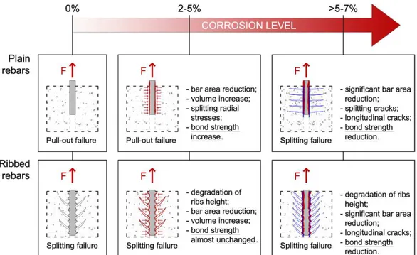
Figure 2.8 - Scheme of the influence of corrosion on bond performance for plain and ribbed reinforcing bars ... 22
Figure 2.9 - Typical stages of a bond-slip relationship for deformed FRP bars [based on (CEB-FIP Report, 2000)] ... 26
Figure 2.10 - Analytical bond-slip relationship for steel reinforcing bar-to-concrete interface ... 31
Figure 2.11 - Analytical bond-slip relationship for FRP reinforcing bar-to-concrete interface ... 32
Figure 2.12 - Geometry and strain energy released of a double-ended crack of length 2c in an infinite plate of unit width under a uniformly applied stress ... 37
Figure 2.13 - Fracture Modes: (a) Mode I – opening; (b) Mode II – in plane-shear (sliding), and (c) Mode III – out-of-plane shear (tearing) ... 38
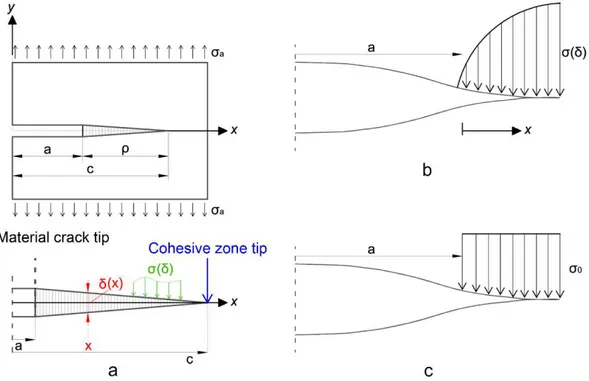
Figure 2.14 - a) Scheme of the cohesive zone ahead of a tensile crack; b) Barenblatt's crack model; and c) Dugdale's crack model ... 41
Figure 2.15 - a) Scheme of the cohesive zone [taken in (Cornec et al., 2003)]; b) FE implementation of CZM [taken in (Cornec et al., 2003)]; and c) typical traction-separation law (TSL) for describing the cohesive behaviour ... 43
Figure 2.16 - TSL: a) Barenblatt’s model; and b) Dugdale’s model ... 45
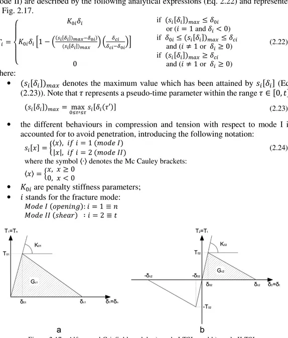
Figure 2.17 - Alfano and Crisfield model: a) mode I TSL; and b) mode II TSL ... 46
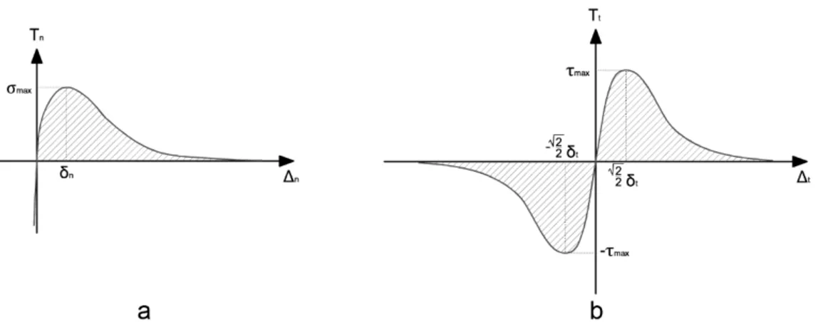
Figure 2.18 - Xu and Needleman model: a) TSL in mode I; and b) TSL in mode II ... 48
Figure 2.19 - Tvergaard's interface model accounting for friction: a) under normal loading; and b) under tangential loading [taken in (Tvergaard, 1990)] ... 49
xvi
[taken in (Chaboche et al., 1997)] ... 50
Figure 2.21 - Lin et al.’s model: a) uncoupled TSL in mode I; and b) uncoupled TSL in mode II accounting for friction [taken in (Lin et al., 2001)] ... 52
Figure 2.22 - RCCM model accounting for friction: a) TSL in mode I; anb b) TSL in mode II [taken in (Raous et al., 1999)] ... 53
Figure 2.23 - Del Piero and Raous model accounting for friction and viscosity: a) TSL in mode I; and TSL in mode II [taken in (Del Piero and Raous, 2010)] ... 53
Figure 2.24 - Scheme of the bipartition of the REA into damaged and undamaged parts 54 Figure 2.25 - Alfano and Sacco model accounting for friction: TSL in mode II [taken in (Alfano and Sacco, 2006)] ... 56
Figure 2.26 - Multiscale approach of the Serpieri and Alfano model (Serpieri and Alfano, 2011): a) smooth macro-interface; b) real interface; and b) periodic micro-pattern of a repeating unit through which the interface is described ... 56
Figure 2.27 - Finite depth of the asperities in the M-CZM ... 57
Figure 2.28 - Typical stress–strain curves for conventional and high performance FRC [after (ACI Committee 544, 1999)] ... 60
Figure 2.29 - Examples of fibre distribution and orientation: a) unidirectional in-plane distribution of continuous long fibres; b) bidirectional in-plane distribution of continuous long fibres; and c) random distribution of discrete short fibres ... 62
Figure 2.30 - a) Toughening effects and crack front debonding, the Cook-Gordon effect (Cook and Gordon, 1964), and debonding and sliding in the crack wake; b) matrix spalling and matrix cracking; c) plastic bending of inclined fibre during pull-out at the crack and at the end-anchor [based on (Löfgren, 2005)]. ... 64
Figure 2.31 - a) Fibre normal to and bridging a matrix tensile crack in a real composite; and b) simulation of the real situation through single fibre pull-out test ... 65
Figure 3.1 - a) Pull-out scheme; b) Pull-out test set-up ... 71
Figure 3.2 - Specimen identification ... 72
Figure 3.3 - ϕ16 mm bar specimens: a) initial configuration, b) final configuration with cut position; ϕ8 mm bar specimens: c) initial configuration, d) final configuration with cut position ... 73
Figure 3.4 - Pull-out results: ϕ8 mm Ti6Al4V rebar from NWC specimen ... 74
Figure 3.5 - Pull-out results: ϕ16 mm Ti6Al4V rebar from NWC specimen ... 75
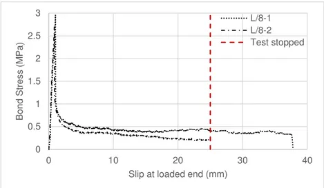
Figure 3.6 - Pull-out results: ϕ8 mm Ti6Al4V rebar from LWC specimen ... 75
Figure 3.7 - Pull-out results: ϕ16 mm Ti6Al4V rebar from LWC specimen ... 76
Figure 3.8 - Examples of local increases in the bond stress noticed in the experimental pull-out curve responses ... 76
Figure 3.9 - a) Partial pull-out test and cut position; b) cross-section; c) bar-matrix interface intended for SEM observations ... 77
Figure 3.10 - SEM observation: specimen N/8-2 ... 79
Figure 3.11 - SEM observation: specimen N/16-2 ... 80
xvii
Figure 3.14 - SEM observations: a) Bar-matrix interfaces of N/8-2, N/16-2, L/8-2 and L/16-2 specimens with indication of the main features; b) Zoom on the interface of N/8-2, N/16-2 and L/16-2 specimens with the indication of the interface measures; c) Legend ... 84 Figure 3.15 - Indirect tensile test fracture surface: a) scheme; b) NWC; c) LWC ... 85 Figure 3.16 - a) Visual and b) Microscopic Analysis of Ti6Al4V bars pulled out from NWC specimens; c) Visual and d) Microscopic Analysis of Ti6Al4V bars pulled out from LWC specimens ... 86 Figure 3.17 - Bond Strength comparison for Plain rebars ... 89 Figure 4.1 - FE model of the specimens with 8 mm bar diameter: a) Geometry; b) Interface details and boundary conditions; and c) Mesh discretisation ... 94 Figure 4.2 - FE model of the specimens with 16 mm bar diameter: a) Geometry; b) Interface details and boundary conditions; and c) Mesh discretisation ... 95 Figure 4.3 - Scheme of the interface: a) initial configuration; and b) deformed configuration
... 96 Figure 4.4 - a) Mode I and Mode II Exponential CZM laws; b) Mode I and Mode II Bilinear CZM laws ... 97 Figure 4.5 - Applied displacement in two substeps for the models with ϕ8 and ϕ16 bars
... 100 Figure 4.6 - ϕ8 mm rebars pull-out from NWC specimens: Comparison between Bilinear (Alfano and Crisfield, 2001) and Exponential (Xu and Needleman, 1994) CZMs and experimental curves ... 101 Figure 4.7 - ϕ16 mm rebars pull-out from NWC specimens: Comparison between Bilinear (Alfano and Crisfield, 2001) and Exponential (Xu and Needleman, 1994) CZMs and experimental curves ... 102 Figure 4.8 - ϕ8 and 16 mm rebars pull-out from NWC specimens, zoom on the elastic branch: Comparison between Bilinear (Alfano and Crisfield, 2001) and Exponential (Xu and Needleman, 1994) CZMs and experimental curves ... 102 Figure 4.9 - ϕ8 mm rebars pull-out from LWC specimens: Comparison between Bilinear (Alfano and Crisfield, 2001) and Exponential (Xu and Needleman, 1994) CZMs and experimental curves ... 103 Figure 4.10 - ϕ16 mm rebars pull-out from LWC specimens: Comparison between Bilinear (Alfano and Crisfield, 2001) and Exponential (Xu and Needleman, 1994) CZMs and experimental curves ... 103 Figure 4.11 - ϕ8 and 16 mm rebars pull-out from LWC specimens, zoom on the elastic branch: Comparison between Bilinear (Alfano and Crisfield, 2001) and Exponential (Xu and Needleman, 1994) CZMs and experimental curves ... 104 Figure 4.12 - ϕ8 mm rebars pull-out from NWC specimens: Comparison between CZM accounting for friction (Alfano and Sacco, 2006) and experimental curves ... 106 Figure 4.13 - ϕ16 mm rebars pull-out from NWC specimens: Comparison between CZM accounting for friction (Alfano and Sacco, 2006) and experimental curves ... 107
xviii
accounting for friction (Alfano and Sacco, 2006) and experimental curves ... 107 Figure 4.15 - ϕ16 mm rebars pull-out from LWC specimens: Comparison between CZM accounting for friction (Alfano and Sacco, 2006) and experimental curves ... 108 Figure 4.16 - a) scheme of the interface; evolution of the normal stress on bar and matrix portions and along the interface: b) substep 10; c) substep 66; d) substep 67; and e) substep 250 ... 109 Figure 4.17 - a) bar and matrix strain distribution along the interface during the bonding stage; and b) bar and matrix strain distribution along the interface during the debonding stage ... 110 Figure 4.18 - a) Purely linear softening CZM: a perfect bond at the beginning of the analysis; b) bar and matrix normal strain and directional deformation distributions along the interface during the bonding stage ... 111 Figure 4.19 - a) Bilinear softening CZM with finite stiffness at the linear-elastic branch; b) bar and matrix normal strain and directional deformation distributions along the interface during the bonding stage ... 111 Figure 4.20 - FE model of the specimens with 16 mm bar diameter and the applied lateral pressure ... 112 Figure 4.21 - Pull-out curve response (up to 5 mm of slip) of ϕ16 mm titanium alloy rebar from NWC specimen, with a CZM accounting for friction and a constant lateral pressure = 100 MPa ... 112 Figure 5.1 - Alfano and Crisfield Bilinear CZM vs Modified law (tangential law) ... 117 Figure 5.2 - ϕ8 mm rebars pull-out from NWC specimens: Comparison between Modified Alfano and Crisfield CZM and experimental curves ... 118 Figure 5.3 - ϕ16 mm rebars pull-out from NWC specimens: Comparison between Modified Alfano and Crisfield CZM and experimental curves ... 118 Figure 5.4 - ϕ8 mm rebars pull-out from LWC specimens: Comparison between Modified Alfano and Crisfield CZM and experimental curves ... 119 Figure 5.5 - ϕ16 mm rebars pull-out from LWC specimens: Comparison between Modified Alfano and Crisfield CZM and experimental curves ... 119 Figure 5.6 - a) body without interface; b) interface model in the initial (undeformed) configuration; and c) interface model in the deformed configuration ... 120 Figure 5.7 - a) the multiscale approach for describing the smooth macro-interface through a periodic pattern of RIA; and b) RIA scheme ... 121 Figure 5.8 - a) RIA initial configuration; RIA deformed configuration: b) reduction in contact area depending on the opening displacement with HN kept constant; and c) HN is updated according to degradation law and then the reduction in contact area is computed ... 126 Figure 5.9 - a) M-CZM with constant area fractions among the microplanes; e: b) higher area fraction for the horizontal microplane; c) higher area fractions for the inclined microplanes; and d) different area fractions among the microplanes ... 126
xix
Figure 5.11 - Typical pull-out curve obtained by employing the enhanced degrading
M-CZM: a) whole curve; and b) enlargement on the first 5 mm of slip ... 130
Figure 5.12 - Identification of the most significant substeps ... 131
Figure 5.13 - Damage variable trend on the three microplanes ... 131
Figure 5.14 - Progressive loss of adhesion on the RIA microplanes during loadstep 1: a) substep 1; b) substep 110; and c) substep 175 ... 132
Figure 5.15 - Evolution of: a) inclination angle ( ); and b) asperities depth ( ) on microplane 1 during loadsteps 1 and 2 ... 132
Figure 5.16 - Influence of the microplane-structured interface... 133
Figure 5.17 - Comparison between the response curves obtained by using the M-CZM (Serpieri et al., 2015a) and the enhanced degrading M-CZM ... 134
Figure 5.18 - Sensitivity to : pull-out curves for the model with ϕ16 mm and NWC obtained by using a RIA consisting of 3 and 5 microplanes ... 137
Figure 5.19 - Sensitivity to : pull-out curves for the model with ϕ16 mm and NWC obtained by using three combination of area fractions ... 138
Figure 5.20 - Sensitivity to : a) NWC; b) LWC ... 140
Figure 5.21 - Sensitivity to : a) NWC; b) LWC ... 142
Figure 5.22 - Sensitivity to : a) NWC; b) LWC ... 144
Figure 5.23 - Sensitivity to : a) NWC; b) LWC ... 146
Figure 5.24 - Sensitivity to : a) NWC; b) LWC ... 148
Figure 5.25 - Numerical-experimental comparison: ϕ16 rebar, NWC ... 150
Figure 5.26 - Numerical-experimental comparison: ϕ16 rebar, LWC ... 150
Figure 5.27 - Numerical-experimental comparison: ϕ8 rebar, NWC ... 151
Figure 5.28 - Numerical-experimental comparison: ϕ8 rebar, LWC ... 151
Figure 5.29 - Substep identification for computing stress distributions at the interface . 152 Figure 5.30 - Normal ( ) and tangential ( ) stress distributions along the interface at different substeps... 153
Figure 5.31 - Normal stress evolution: a) Loadstep 1 - substep 30 (bonding phase); b) Loadstep 1 - substep 68 (pull-out force peak); and c) Loadstep 2 - substep 100 (post-debonding/frictional phase)... 154
Figure 5.32 - Tangential stress evolution: a) Loadstep 1 - substep 30 (bonding phase); b) Loadstep 1 - substep 68 (pull-out force peak); and c) Loadstep 2 - substep 100 (post-debonding/frictional phase)... 154
Figure 6.1 - Pull-out test configurations: a), b) and c) single-sided specimens; d) double-sided specimens ... 158
Figure 6.2 - Typical bond-slip response curve of: a) straight fibre; and b) hooked-end fibre; c) comparison between straight and hooked-end fibre in terms of bond-slip response curve ... 160
Figure 6.3 - Geometric details of: a) smooth straight; and b) hooked-end Ti6Al4V fibres ... 163
xx
Figure 6.5 - Geometrical details of the specimens for the single fibre pull-out test: a) perspective view; b) longitudinal cross-section (Section V-V’); and c) transversal cross-section (Section H-H’) ... 164 Figure 6.6 - Pull-out test set-up: a) scheme of the test; b) execution of the test ... 164 Figure 6.7 - Pull-out test details: a) testing machine; b) metallic frame; c) clamping device; and d) strain gauges ... 165 Figure 6.8 - Specimen identification ... 165 Figure 6.9 - Single fibre pull-out test results: Straight fibre ... 167 Figure 6.10 - Zoom on the first 5 mm of slip of the single fibre pull-out test results: Straight fibre ... 167 Figure 6.11 - Single fibre pull-out test results: Hooked-end fibre ... 168 Figure 6.12 - Zoom on the first 10 mm of slip of the single fibre pull-out test results: Hooked-end fibre... 168 Figure 6.13 - Hooked-end fibres after pull-out test ... 169 Figure 6.14 - Bond-slip response curve comparison between straight and hooked-end fibres
... 169 Figure 6.15 - Fibre pull-out mechanism: a) rigid sliding of straight fibres; and b) plastic deformation (strengthening) of the hook of hooked-end fibres ... 171 Figure 6.16 - Plastic hinges: a) hooked-end fibre with two curvatures; and b) hooked-end fibre with three curvature ... 171 Figure 6.17 - Comparison between pull-out response curves of hooked-end fibres: a) hook plastic deformation response; and b) hook rupture response ... 172 Figure 6.18 - a) plastically deformed hook (specimen L/PO_HE-7); and b) broken hook (specimen L/PO_HE-6) ... 172 Figure 6.19 - Average curve: a) straight fibres series; and b) hooked-end fibres series . 174 Figure 6.20 - Pull-out Load-slip average curves: a) ϕ16 mm bar in LWC specimens (L/PO_B16); b) ϕ8 mm bar in LWC specimens (L/PO_B8); and c) ϕ1.2 mm fibres in LWC specimens (L/PO_S1.2) ... 175 Figure 6.21 - 2D axisymmetric FE model of the single straight fibre pull-out tests: a) geometry, b) boundary conditions; and c) mesh discretisation ... 178 Figure 6.22 - Comparison between the experimental average curve and the numerical curve obtained with the enhanced degrading M-CZM: curve until a slip equal to 12.5 mm; and zoom on the first 2.5 mm of slip ... 180 Figure 7.1 - Typical profiles of steel fibres used in concrete according to Naaman (Naaman, 2003) ... 184 Figure 7.2 - Softening and hardening behaviour of FRC: a) tension-softening; b)
deflection-softening; c) tension-hardening; and d) deflection-hardening... 186 Figure 7.3 - Corrosion mechanisms on: a) un-cracked concrete; b) cracked concrete at an early stage; c) cracked concrete after autogenous healing; d) cracked concrete with critical corrosion on fibres [based on (Marcos-Meson et al., 2017)]. ... 188
xxi
set up and specimen dimensions; b) details of the notch and the transducer ... 190
Figure 7.5 - Example of the load- response of a 3PBT with the indication of , and the respective ... 191
Figure 7.6 - Fibres geometry hooked-end configurations: a) Titanium Grade 2; b) Titanium Grade 5 ... 192
Figure 7.7 - Cast #1 (Ti-gr2FRC) scheme ... 193
Figure 7.8 - Cast #2 (Ti-gr5FRC) scheme ... 194
Figure 7.9 - Cast #3 (Plain concrete) scheme ... 194
Figure 7.10 - Test set-up and execution: a) compression test; b) indirect tensile test ... 195
Figure 7.11 - Specimen dimensions for the three-point bending test ... 195
Figure 7.12 - Three-point bending test set-up ... 196
Figure 7.13 - Compression test broken specimens: a) Ti-gr2_CT-1; b) Ti-gr5_CT-1; c) P_CT-1 ... 199
Figure 7.14 - Results of the 3PBT on Ti-gr2FRC (complete curves and zoom on the first part up to =0.5 mm) ... 199
Figure 7.15 - Results of the 3PBT on Ti-gr5FRC (complete curves and zoom on the first part up to =0.5 mm) ... 200
Figure 7.16 - Results of the 3PBT on Plain Concrete (complete curves and zoom on the first part up to =0.5 mm) ... 200
Figure 7.17 - Broken specimens after the 3PBT on Ti-gr2FRC ... 203
Figure 7.18 - Broken specimens after the 3PBT on Ti-gr5FRC ... 204
Figure 7.19 - Broken specimens after the 3PBT on Plain Concrete (P) ... 205
Figure 7.20 - Geometry of the Ti-gr5FRC full-scale beam ... 208
Figure 7.21 - Test set-up: a) test apparatus with load steps indication; b) position of the extensometer 1; c) position of the extensometer 2; and c) detail of the steel beam used to transfer the load ... 209
Figure 7.22 - Beam under progressive load-step... 210
Figure 7.23 - Failure mechanisms: a) multiple and diffusive cracking; b) plastic deformation of the fibres hook; and c) bridging action of the fibres ... 211
xxii
Table 2.1 - Main mechanical properties of Titanium Grade 2 and 5 ... 8 Table 2.2 - Layer models review for bond modelling ... 33 Table 2.3 - Review of fracture mechanics approaches to bond modelling ... 34 Table 2.4 - Review of potential and nonpotential-based formulation of CZMs ... 44 Table 2.5 - Comparison among different materials used as fibre reinforcement for concrete
... 61 Table 3.1 - NWC and LWC concrete mixtures mix design ... 68 Table 3.2 - Control specimens’ characteristics - compression test ... 68 Table 3.3 - Mechanical properties of concrete: Compression test results ... 69 Table 3.4 - Control specimens’ characteristics - indirect tensile test ... 69 Table 3.5 - Mechanical properties of concrete: Indirect Tensile test results ... 70 Table 3.6 - Mechanical properties of Titanium alloy: Tensile test results ... 70 Table 3.7 - Properties of Ti6Al4V bars: manufacturer specifications and experimental results ... 71 Table 3.8 - Specimens for the pull-out test ... 72 Table 3.9 - Experimental pull-out test results ... 74 Table 3.10 - Bond strength values comparison for plain rebars ... 87 Table 3.11 - Bond strength values comparison for ribbed rebars ... 90 Table 4.1 - Material properties for the FE analysis ... 95 Table 4.2 - Experimental interface delamination parameters for Mode II dominated fracture behaviour ... 97 Table 4.3 - Parameter values for Exponential CZM ... 98 Table 4.4 - Parameter values for Bilinear CZM ... 100 Table 4.5 - Analysis settings ... 100 Table 4.6 - Input parameters for the CZM accounting for friction proposed by Alfano and Sacco (Alfano and Sacco, 2006) ... 106 Table 5.1 - Input parameters for the modified Alfano and Crisfield model ... 117 Table 5.2 - Input parameters for the enhanced degrading M-CZM ... 127 Table 5.3 - Initial set of enhanced degrading M-CZM input parameters ... 129 Table 5.4 - Fixed input parameters for the enhanced degrading M-CZM ... 135 Table 5.5 - Enhanced degrading M-CZM input parameters for sensitivity analysis to
... 136 Table 5.6 - Enhanced degrading M-CZM input parameters for sensitivity analysis to 0
... 138 Table 5.7 - Enhanced degrading M-CZM input parameters for sensitivity analysis to 0
xxiii
... 141 Table 5.9 - Enhanced degrading M-CZM input parameters for sensitivity analysis to 0
... 143 Table 5.10 - Enhanced degrading M-CZM input parameters for sensitivity analysis to 0
... 145 Table 5.11 - Enhanced degrading M-CZM input parameters for sensitivity analysis to
... 147 Table 5.12 - Final values of enhanced degrading M-CZM input parameters after identification procedure ... 149 Table 6.1 - Most used steel fibre profiles ... 159 Table 6. 2 - LWC mix design ... 161 Table 6.3 - Mechanical properties of LWC... 161 Table 6.4 - Mechanical properties of the titanium wires (provided by the manufacturer)
... 162 Table 6.5 - Single fibre pull-out test results ... 166 Table 6.6 - Hook contribution ... 173 Table 6.7 - Comparison between bar and fibre pull-out tests ... 175 Table 6.8 - Material properties for the FE analysis ... 179 Table 6.9 - Enhanced degrading M-CZM input parameters for the single fibre pull-out test FE simulation ... 179 Table 7.1 - Mechanical properties of the titanium wires provided by the manufacturer 192 Table 7.2 - Cast details and specimen identification for each batch ... 193 Table 7.3 - Specific weight of the three concrete batches ... 197 Table 7.4 - Compression and indirect tensile tests results ... 198 Table 7.5 - 3PBT results ... 201 Table 7.6 - comparison ... 202 Table 7.7 - Flexural strength and residual flexural strength comparison between Ti-gr5FRC and SFRC ... 206 Table 7.8 - Mechanical properties of the concrete batch ... 208 Table 7.9 - Results of the test on the full-scale Ti-gr5FRC beam ... 210
1
Chapter 1
Introduction
Corrosion of reinforcement in reinforced concrete structures has been recognised as the predominant factor causing premature deterioration of concrete buildings worldwide (Böhni, 2005). Carbonation-induced and chloride-induced corrosion prevails as the most serious mechanisms leading to loss of bearing capacity of reinforced concrete civil structures around the globe (Zhou et al., 2014). Direct consequences of reinforcement corrosion are the severe reduction of reinforcement cross-sectional area and the formation of expansive products formation at the reinforcement-concrete interface, which in turn causes the cracking and spalling in concrete cover. Aggressive environments, such as the marine environment, weather conditions, fatigue and changing of loading conditions on reinforced concrete structures have been established as major factors promoting chloride penetration and carbonation phenomenon (Zhou et al., 2014), (Apostolopoulos, 2016). Recently, the impact of global warming on chloride ingress has been also reported to be a crucial factor that has to be accounted for in the assessment of the structural behaviour of reinforced concrete structures (Bastidas-Arteaga, 2018).
All the previous considerations are actually translated in the need of repairing or replacing those structures that suffer by steel corrosion. This appears to be imperative in the case of those buildings which are places of large gatherings such as schools and hospitals (Apostolopoulos, 2016), and in the case of civil infrastructures, such as bridges, highways, on-shore and off-shore structures, which moreover are severely exposed to the environmental action (Zhou et al., 2014). The poor durability of many concrete infrastructures, which results in short structural service lives, is not sustainable neither in social nor in economic terms (Navarro et al., 2018). In a recent study published by NACE International, called ‘IMPACT - International measures of prevention, application, and economics of corrosion technologies study’ (Koch et al., 2016), it is reported that “the global cost of corrosion is estimated to be US$2.5 trillion, which is equal to 3.4% of Global Domestic Product (GDP)”.
2
Therefore, it appears clear how novel strategies for preventing corrosion and protecting reinforced structures of various types and importance (e.g. bridges, nuclear structures, hospitals, schools etc.) in order to guarantee structural safety, are encouraged and often crucial. In this background, over decades many efforts have been made by researchers to improve the durability of reinforced concrete structures. The possibility of adding corrosion inhibitors in the concrete mixture, as well as coating the steel rebar surface with both metallic and organic films oriented to improve the reinforcement corrosion resistance, has been largely investigated. Moreover, a vast amount of research is oriented to the replacement of traditional steel reinforcement with reinforcement that does not corrode, such as stainless steel rebars and non-metallic ones (e.g. Fibre Reinforced Polymers). Thus, the need of alternative solutions and strategies able to limit the problem of reinforcement corrosion in reinforced concrete structures is increasingly crucial.
A material that has never been thoroughly investigated as potential reinforcement for concrete structures is titanium, clearly because of its cost. However, titanium and its alloys have outstanding properties in terms of corrosion resistance and excellent strength-to-specific weight ratio. Thus, for special designs where avoiding reinforcement corrosion and reducing structure self-weight are crucial to the point to justify high costs, titanium may become a realistic option.
In the present thesis the possibility to use titanium and its alloys as concrete reinforcement has been investigated by starting from the main prerequisite of understanding the behaviour that titanium and concrete develop when they are in contact, i.e. the bond performance. Therefore, experimental tests and numerical analyses aimed to the comprehension of the titanium-concrete interface mechanisms have been carried out by focusing not just on traditional reinforcing bars, but also on diffused reinforcement, i.e. discrete fibres randomly distributed in the concrete matrix. To emphasise the high strength-to-weight ratio of titanium alloys, lightness has been another pursued objective. In this respect, lightweight aggregate concrete mixes have been taken into account, considering also that they usually suffer corrosion of embedded reinforcement (reinforcing bars or fibres) even more than normal-weight concrete due to their higher porosity.
A first evaluation of the bond performance is made between plain reinforcing bars and normal and lightweight concrete matrices, by carrying out experimental pull-out tests. Plain bars were selected in order to better understand the influence that the particular material used for the reinforcement and the different types of concrete batches designed have on the pull-out response. Additionally, by using plain rebars and analysing the problem from a micro-mechanical point of view, the role of surface roughness can be more easily identified. To this end, the experimental tests have been supported by finite element analyses in which the debonding process has been described through several cohesive zone models. The known formulations of exponential (Xu and Needleman, 1994) and bilinear (Alfano and Crisfield, 2001) cohesive zone models, and those accounting for friction (e.g. the model proposed by Alfano and Sacco in (Alfano and Sacco, 2006)) have been considered and implemented in order to verify their capacity of describing the phenomenon under exam. However, by applying these models, unsatisfactory results have been obtained, underlining the necessity of using a model able to account for the micromechanisms
3
actually acting at the interface during pull-out. Therefore, other modelling strategies have been adopted, by formulating and implementing into the finite element software two novel cohesive zone models. The first one is derived by the bilinear model formulation introduced by Alfano and Crisfield (Alfano and Crisfield, 2001) and accounts for a further exponential branch which simulates the combined action of friction and dilatancy in a phenomenological manner. Even though this model has led to very good agreement between experimental and numerical results, its empirical approach could not allow the comprehension of the real mechanisms governing the debonding. Thus, the micromechanics-based formulation of the angle-degrading multiplane cohesive zone model developed by Serpieri et al. in (Serpieri et al., 2015a) has been adopted and enhanced by introducing, as a novel mechanical feature, the reduction of the asperities depth induced by wear and degradation. The resulting model, here denominated ‘enhanced degrading M-CZM’, permits to outline the individual role of each damaging mechanism in the overall system response, considering also effects induced by the rebar surface roughness which are usually neglected in the finite element simulation of pull-out tests.
Secondly, the possibility to include titanium alloy fibres into a lightweight concrete matrix is investigated. To this end, single fibre pull-out tests have been carried out to estimate the bond behaviour between titanium-alloy fibres and concrete and evaluate the differences between bars and fibres behaviour under pull-out conditions. The numerical analysis by employing cohesive zone models for the debonding simulation is again used as a tool to better identify the interfacial micromechanisms. Straight and deformed configurations of reinforcing fibres were tested, resulting in different failure modes that strongly affect the behaviour of a composite fibre reinforced material. Therefore, after analysing both experimentally and numerically the behaviour of single fibres embedded in lightweight concrete, a titanium-alloy-fibre reinforced (lightweight) concrete (TiFRC) has been designed and tested. A series of three-point bending tests on TiFRC specimens and a bending test on a TiFRC full-scale beam have been carried out in order to quantify the flexural performance of the new material proposed and compare it to the flexural behaviour of the well-known steel fibre reinforced concrete. Tests on specimens of reduced dimensions and on a full-scale beam allowed also to quantify the size effect on the flexural strength.
1.1
Research significance and objectives
Despite the well-known high cost of titanium and its alloys, some novel applications in the field of civil structural engineering have been recently proposed and realised (Higgins et al., 2017), demonstrating that titanium alloys can be a realistic alternative to traditional materials used for reinforcing concrete. The applications proposed in (Higgins et al., 2017) concern the flexural and shear strengthening of reinforced concrete beams. Nevertheless, there still is lack of information about the bond relationship that titanium and concrete can develop, which, however, represents a crucial step towards the possibility to combine them in a composite structural material, either when longitudinal reinforcing bars and distributed short fibres are concerned.
4
The present thesis is intended as a preliminary study towards the possibility of combining titanium alloys and concrete, providing a series of experimental results and a comprehensive comparison with the literature on the same tests on more traditional materials. The objectives of the thesis are summarised as follows:
• characterise the bond behaviour between titanium alloys and concrete from the mechanical point of view;
• understand the micromechanisms acting at the interface during debonding in the case of plain smooth reinforcement;
• use numerical analysis as a tool to better understand the mechanisms governing the reinforcement-matrix failure, by implementing also novel cohesive zone models able to account for such mechanics;
• compare the bond performance of bars of different diameters and fibres with respect to different concrete matrices from both the experimental and numerical point of view;
• design and test a lightweight fibre reinforced concrete material with titanium alloy fibres, evaluating the flexural strength and the post-peak behaviour of the novel material.
1.2
Thesis outline
The outline of the thesis is as follows: Chapter 2 is a literature survey on the fundamental topics analysed in the present research. It consists of two parts, the first of which reports the main characteristics of titanium and its alloys and their existing applications in the field of civil structural engineering. Part 2 of the literature review, instead, is focused on the importance of bond behaviour between concrete and various types of reinforcement either in the case of traditional reinforced concrete structures and in the case of fibre reinforced concrete materials. Experimental methods and numerical techniques developed to evaluate and predict the bond performance are discussed. Moreover, particular attention is focused on the behaviour of plain bars under pull-out conditions, since its importance in understanding the basic mechanisms acting at the reinforcement-concrete interface. Chapter 3 reports the experimental tests carried out on plain titanium alloy bars from two different concrete matrices, differing only for the coarse aggregates phase, which consists of normal and lightweight aggregates, respectively. Pull-out test results provided the so-called bond-slip relationships, that have been used to compare the bond performance of the titanium alloy-concrete interface with that provided by employing more traditional reinforcement materials (steel, fibre reinforced polymers, etc.) found in the literature. Further investigations concern the analysis of the broken interfaces by means of the scanning electron microscope, which provided useful information to catch the micromechanisms acting at the interface during debonding. Chapters 4 and 5 report the finite element analyses carried out in order to simulate the experimental testes carried out and presented in Chapter 3. Cohesive zone models are employed in the finite element analyses to simulate the interface fracture. Chapter 4 presents the numerical models and analysis settings adopted for the analysis, and the results obtained by using some of the
5
most widely used cohesive zone models (i.e. Xu and Needleman exponential model (Xu and Needleman, 1994), and Alfano and Crisfield bilinear formulation (Alfano and Crisfield, 2001)), including one model accounting for friction (Alfano and Sacco, 2006). Thus, their limitations in describing the problem under exam have been analysed and Chapter 5 reports two novel formulations of cohesive zone models, able to describe the experimental results. Particularly, sensitivity analyses, identification and validation procedures for the enhanced degrading M-CZM here formulated are included in Chapter 5. Chapters 6 and 7 concern the characterisation of the mechanical properties of lightweight concrete reinforced with distributed titanium alloy fibres (TiFRC). Particularly, Chapter 6 reports the results of single fibre pull-out tests carried out on titanium fibres of two different geometrical configurations from lightweight concrete specimens. The experimental tests are supported by finite element analyses which include the cohesive zone models formulated in Chapter 5. Chapter 7, instead, presents preliminary experimental results of three-point bending tests on TiFRC specimens and a final experimental test on a TiFRC full-scale beam. Conclusions are drawn in Chapter 8, where open issues and suggestions for future research that would investigate titanium as potential reinforcement for concrete are also discussed.
7
Chapter 2
Literature review
This chapter contains a literature survey on the fundamental topics discussed in the present thesis. It consists of two main sections here called ‘Part 1’ and ‘Part 2’, respectively. In Part 1 the general properties of titanium and its alloys, as well as their existing uses in the field of civil-structural engineering, are analysed. Part 2, instead, reviews several essential aspects at the basis of the applications here hypothesised for titanium, such as bond behaviour between concrete and reinforcement, numerical modelling techniques adopted for interface problems, and fibre-reinforced cementitious materials.
Part 1 - Titanium and titanium alloys: main characteristics
and existing uses in civil structural engineering
2.1 Main properties of titanium and its alloys
Titanium is a low-density element (Symbol ‘Ti’; atomic number 22; and atomic weight 47.9) discovered in 1791 by the British reverend, mineralogist and chemist, William Gregor (Leyens and Peters, 2003). Four years later, Martin Klaproth, a Berlin chemist, isolated titanium oxide. However, it took more than 100 years to isolate the proper metal. The first alloys, including today’s most popular Ti6Al4V (i.e. Titanium, 6% Aluminium and 4% Vanadium), were developed in the late 1940s in the United States and commercial production of titanium did not begin until the 1950s (RTI, 2013). Today, the peculiar properties of titanium and its alloys are exploited in many industrial applications, especially in the field of aerospace and chemical industries. But other markets such as architecture, chemical processing, medicine, power generation, marine and offshore, sports and leisure, and transportation are experimenting increasing application of titanium.
8
Titanium is not actually a rare substance, as it ranks as the fourth most plentiful structural metal in the Earth’s crust exceeded only by aluminium, iron, and magnesium. Nevertheless, it is never found in a pure state, since it usually occurs in mineral sands containing ilmenite (FeTiO3) or rutile (TiO2). Thus, the difficulties in processing titanium
makes it expensive.
Titanium and its alloys exhibit a unique combination of mechanical and physical properties and excellent corrosion resistance. The primary attributes of these alloys are:
• Elevated strength-to-density ratio (high structural efficiency);
• Low density (roughly half the weight of steel, nickel and copper alloys);
• Exceptional corrosion resistance to vast range of chemical environments (excellent resistance to chlorides and seawater);
• Excellent elevated temperature properties (up to 600°C); • Essentially nonmagnetic.
Mill products, available in both commercially pure and alloy grades, can be grouped into three categories according to the predominant phase or phases in their microstructure, i.e. , - , and . Each category offers a unique suite of properties which may be advantageous for a given application, despite it requires a specific mill processing methodology.
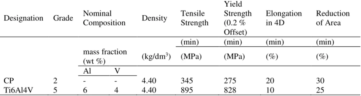
Among the numerous available titanium alloys, titanium Grade 2, i.e. unalloyed titanium (also called “Commercially Pure”), and titanium Grade 5, i.e. - alloy consisting of titanium, aluminium and vanadium (the alloy Ti6Al4V), represent the most widely adopted grades of titanium. Their main mechanical properties are summarised in Table 2.1.
Table 2.1 - Main mechanical properties of Titanium Grade 2 and 5 Designation Grade Nominal Composition Density Tensile Strength
Yield Strength (0.2 % Offset) Elongation in 4D Reduction of Area (min) (min) (min) (min) mass fraction
(wt %) (kg/dm3) (MPa) (MPa) (%) (%) Al V
CP 2 - - 4.40 345 275 20 30
Ti6Al4V 5 6 4 4.40 895 828 10 25
2.2 Applications of titanium and its alloys in civil structural
engineering
The major fields of application of titanium and its alloys are those requiring high level of sophistication, such as biomedical, aerospace and mechanical engineering, mainly due to their cost. Concerning applications in civil structural engineering, currently the panorama is quite limited, but there are some particular cases where titanium has been chosen for its peculiar characteristics.
9 2.2.1 Monumental restoration
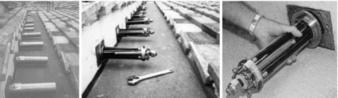
Because of its lightness, its compatibility with materials such as marble and stone and, above all, its outstanding resistance to corrosion, titanium has been used for the consolidation of monumental buildings of historical-artistic importance. The main applications concern the replacement of existing steel bars with titanium ones, and the consolidation of damaged portions with titanium plates and bars. Some examples of this kind of restoration, shown in Fig. 2.1, are the Parthenon of Athens (Karanassos, 2014), (Dakanali et al., 2016), the Column of Marco Aurelio in Rome (Masiani and Tocci, 2012), and the bell tower of San Marco in Venice (Cecconi et al., 2008).
Figure 2.1 - Applications of titanium in monumental restoration: a) titanium bars into pre-drilled holes in the columns of the Parthenon of Athens (Karanassos, 2014); b) restoration of the Column of Marco Aurelio in Rome with titanium bars and plates (Masiani and Tocci, 2012); c) consolidation of
the foundations of the San Marco bell tower in Venice with titanium bars (Cecconi et al., 2008) As for the restoration of the Acropolis of Athens, the technique used consists in re-joining the fractured marble elements by inserting titanium bars into pre-drilled holes. Then the holes are filled with a particular cement-based paste. To assess the compatibility between titanium and marble some investigations on the pull-out behaviour of the rod from marble elements have been carried out in (Dakanali et al., 2016), concluding that the cement-threaded bar interface does not fail during the whole loading procedure, contrary to what happens to the marble-cement interface.
Since the possibility to use the ‘near surface mounted reinforcement’ (NSM) technique, the hooping of columns by means of titanium belts is a type of consolidation that has been applied in the case of the Monastery of Santa Monica in Cremona (Dolce et al., 2001) and the Abbey of San Pietro in Perugia (Vetturini, 2014), as shown in Figs. 2.2a and 2.2b, respectively.
10
Figure 2.2 - Titanium belts for hooping historical columns: a) Monastery of Santa Monica, Cremona (Dolce et al., 2001); and b) Abbey of San Pietro, Perugia (Vetturini, 2014)
Another titanium-based intervention in the field of monumental restoration that it is worth mentioning, is represented by the devices made of Shape Memory Alloys (SMAs) applied to the Basilica of San Francesco in Assisi (Croci, 1998), (Castellano and Martelli, 2000), (Castellano, 2005) (Fig. 2.3). SMAs are a unique class of metal alloys that can recover apparent permanent strains at the moment in which the load is removed (pseudoelasticity) or when they are heated above a certain temperature (shape memory effect). Among other SMAs, the most used one is the so-called nitinol, constituted approximately by 56% of Nickel and 44% of Titanium (Abdulridha et al., 2013). Due to these characteristics, devices in SMA are able to greatly improve the dissipative capacity of buildings (Fig. 2.4).
Figure 2.3 - Shape memory alloy devices installed in the Basilica of San Francesco, Assisi (Castellano, 2005)
11
Figure 2.4 - a) Nitinol bars applied as further reinforcement in a RC beam; stress-strain response: b) without nitinol bars; and c) with nitinol bars
2.2.2 Cathodic protection systems
A non-negligible field of application of titanium in civil engineering and, particularly, in reinforced concrete structures is represented by cathodic protection systems of reinforcements. In this case the exploited characteristics of titanium are its excellent corrosion resistance and its capacity to behave as an ‘anode’, i.e. the capacity of distributing the protective current across the structure (Clemena and Jackson, 2002). A cathodic protection system for reinforced concrete consists of a number of basic components, including the reinforcement to be protected, an anode, a power source, concrete surrounding the steel, a monitoring system, and cablings to carry the system power and monitoring signals (Chess and Grønvold & Karnov, 1998). Each cathodic protection system contains two types of anodes, i.e. the ‘anode conductor’ acting as a contact point and a power supply line for the secondary anode, and the proper ‘anode’ that distributes the current over the surface of the structure (Kepler and Locke, 2000). The most used types of proper anodes are: platinum anodes and expanded titanium mesh anodes. Titanium mesh anodes consist of a titanium grid, coated with a metal oxide catalyst (Hayfield and Warne, 1989) (Virmani and Clemena, 1998).
2.2.3 Strengthening of reinforced concrete beams
In the field of civil structural engineering the strengthening of older structures plays a major and fundamental role. A new method of supplemental reinforcing involving titanium for use in a near-surface mounting (NSM) application has been recently proposed by
12
Higgins et al. (Higgins et al., 2017). In this method, titanium alloy bars are bonded with structural adhesive within grooves that are cut into the surface of the concrete member. The materials and implementation approach were demonstrated in the laboratory on full-size specimens (Fig. 2.5) and were then applied to a RC bridge in the US that contained poorly detailed flexural steel reinforcement and exhibited significant distress. The behaviour of the whole structure after this intervention resulted in a significant improving of the structural capacity in terms of flexure and shear resistance (Higgins et al., 2017).
Figure 2.5 - Flexural Strengthening of RC beam with titanium rods in the experiment by Higgins et al. [taken in (Higgins et al., 2017)]
In the application proposed by Higgins et al. (Higgins et al., 2017), it is worth underlining that the near surface mounting technique was possible only due to the excellent corrosion resistance characterising the titanium rods. Moreover, since the yield strength of the titanium alloy selected is more than double than that of steel (i.e. ~1000 MPa vs. 450 MPa), only four 16 mm bars were needed to provide the required member strengthening.
The experiment carried out by Higgins et al. (Higgins et al., 2017) led the authors to conclude that the application of only four titanium alloy bars increased both the girder strength by a factor of two and its deformation capacity. In addition, titanium reinforcing bars have been also developed for the shear strengthening by adopting also in this case the NSM technique. Particularly, tests were carried out on T-shaped cross-section beams. The
13
results of the test confirmed an improvement of 40% in the shear performance of the beam. Therefore, the titanium-based shear strengthening would have shifted from non-ductile shear failure to ductile flexural failure.
The flexural strengthening technique tested in the laboratory was then applied to a real bridge, obtaining very successful results not only in terms of technical performance but also from the economic point of view. In fact, no shoring or posting techniques were required and the final cost of the operation was 30% lower than the possible alternatives, i.e. stainless steel and carbon fibre bars (Higgins et al., 2017), (Knudtsen, 2016).
Thus, Higgins et al. (Higgins et al., 2017) concluded in their study that titanium can be considered a promising material for strengthening civil infrastructures.
2.2.4 Concluding considerations
Few applications of titanium and titanium alloys in the field of civil-structural engineering have been found in the literature, due to the high cost of the material. However, for some restorations of historical monuments, the advantages obtained by using different titanium alloys reinforcing strategies could overcome the high costs of this class of metals. Furthermore, a recent application of titanium alloy bars demonstrated the remarkable advantages that can be obtained by employing this material in reinforced concrete structures. The possibility to use a near surface mounting technique due to the excellent corrosion resistance and the reduction in the number of bars due to the high strength of the considered titanium alloys, revealed that this material could be a valuable alternative to other materials traditionally employed for the same scope. Moreover, an economic analysis carried out in (Knudtsen, 2016) highlighted that, even though the cost of the material itself is higher, for some applications the labour cost is much higher when other materials, such as carbon fibre and stainless steel, are used.
14
Part 2 - Reinforcement-to-concrete interface behaviour:
from reinforcing bars to fibres
The second part of the literature review investigates the aspects related to the concrete-reinforcement interface behaviour. In the present research, the considered types of reinforcement are both traditional bars for reinforced concrete (RC) structures and fibres for reinforced cementitious materials. Thus, in the first instance, the bond behaviour between rebars and concrete is examined from the experimental and numerical point of view, with particular attention to the factors affecting bond and to the mechanisms acting in the case of plain steel reinforcing bars. Moreover, with regard to steel rebars, the influence of corrosion on the bond performance is taken in consideration. In fact, corrosion is the main reason why alternative materials for reinforcement have been proposed in the literature. A review of the most widely adopted alternative reinforcements in terms of bond performance is also made here.
In the second instance, the general behaviour of fibre reinforced cementitious materials is considered with regard to the mechanisms governing the fracture process. Among these mechanisms, especially those concerning the fibre-matrix interface failure are analysed.
2.3 Bond behaviour between reinforcing bars and concrete
2.3.1 General conceptsReinforcement-to-concrete bond is the phenomenon which allows longitudinal forces to be transferred from the reinforcement to the surrounding concrete in a RC structure (CEB-FIP Report, 2000). Reliable and efficient force transfer is essential to make RC to behave as a composite structural material. The force transfer process does not involve the whole reinforcement uniformly, so that the force in a reinforcing bar changes along its length, as the force does in the concrete cover. To prevent the discontinuity, i.e. the separation of the two materials, the reinforcing element has to undergo the same strain as the surrounding matrix. Wherever this does not happen, i.e. reinforcement strains differ from concrete ones, a relative displacement (slip) between the two occurs (CEB-FIP Report, 2000).
A vast amount of research has been carried out over the last decades, providing an ever-improving understanding of this aspect of reinforced concrete behaviour. Unsurprisingly, bond behaviour has been widely investigated with regard to steel reinforcing bars, and the resistant mechanisms upon which the steel-concrete bond is based, are well known (CEB-FIP Report, 2000). However, the rebar-matrix interface represents a very complex and inhomogeneous zone (Angst et al., 2017), and bond performance is still a crucial topic under investigation. As for steel reinforcement, many studies are focused on the influence of corrosion on bond performance (Almusallam et al., 1996), (Lundgren, 2005), (Cairns et al., 2007), (Coccia et al., 2016). In addition, especially in the last decades, a vast amount of research has investigated the bond performance between both different reinforcements
![Figure 2.21 - Lin et al.’s model: a) uncoupled TSL in mode I; and b) uncoupled TSL in mode II accounting for friction [taken in (Lin et al., 2001)]](https://thumb-eu.123doks.com/thumbv2/123dokorg/2968168.27085/76.892.180.720.187.394/figure-lin-model-uncoupled-uncoupled-accounting-friction-taken.webp)
![Figure 2.22 - RCCM model accounting for friction: a) TSL in mode I; anb b) TSL in mode II [taken in (Raous et al., 1999)]](https://thumb-eu.123doks.com/thumbv2/123dokorg/2968168.27085/77.892.152.737.179.447/figure-rccm-model-accounting-friction-tsl-taken-raous.webp)
![Figure 2.25 - Alfano and Sacco model accounting for friction: TSL in mode II [taken in (Alfano and Sacco, 2006)]](https://thumb-eu.123doks.com/thumbv2/123dokorg/2968168.27085/80.892.254.642.193.428/figure-alfano-sacco-model-accounting-friction-alfano-sacco.webp)