NOTA: tagliare il blocco di pagine della tesi (stampata fronte-retro)
lungo le due linee qui tracciate prima di effettuare la rilegatura
N
O
T
A
: a
nc
he
q
ue
st
a
pa
gi
na
b
ia
nc
a
fa
p
ar
te
d
co
d
i p
ag
in
e
de
lla
te
si
Francesco Pagano
SMART SYSTEMS BASED ON
ELECTROACTIVE POLYMERS
Doctor of Philosophy Thesys in Ingegneria Elettronica,
Automatica e del Controllo dei Sistemi Complessi
(XXV Cycle)
Coordinatore:
Chiar.mo Prof. Ing.
Luigi Fortuna
Tutor:
Chiar.mo Prof. Ing.
Salvatore Graziani
my graduate and undergraduate career.
A great deal of thanks is owed to Prof. Salvatore Graziani for its input on my research.
Finally I would like to thank everyone I worked with at University of Catania for the help they provided.
Chapter 1... 11
INTRODUCTION... 11
1. Ionic Polymer-Metal Composites (IPMC)... 11
1.1. IPMCs ... 12
1.2. IPMC Actuating and Sensing Mechanism... 14
1.3. IPMC Modeling... 17
1.4. IPMC Applications... 22
2. Ionic Polymer - Polymer Composites (IP2C)... 28
3. Experimental Set-up... 31
3.1. Conditioning circuitry ... 33
Chapter 2... 37
A SMALL SCALE VISCOMETER BASED ON IPMC ... 37
1. Introduction ... 37
2. The first version... 38
2.1. The Model ... 39
2.2. Experimental set-up ... 44
2.3. First Version Results... 46
3. The Second Version ... 48
3.1. The model ... 50
3.2. Experimental set-up ... 53
3.3. Results ... 54
4. Conclusions ... 58
SEISMIC SENSOR ... 59
1. Introduction ... 59
2. The realized system ... 60
2.1. The working principle... 60
2.2. The real device... 62
2.3. The experimental results ... 63
3. The Device Modeling ... 68
4. Conclusions ... 73
Chapter 4... 75
POWER HARVESTING... 75
1. Introduction ... 75
2. Investigation of IP2C Energy Harvesting properties... 76
2.1. Characteristics of the used transducers... 76
2.2. Experimental set-up ... 78
2.3. Results ... 81
3. Bi-Stable Power Scavenger ... 86
3.1. Prototype Development ... 87 3.2. Results ... 89 4. Conclusions ... 94 Research Conclusions... 95 APPENDIX... 99 1. Viscometer ... 99
1.1. Concentrative Properties Of Sucrose Solutions C12H22O11... 99
1.2. error minimization algorithm for the search of the parameters of the IPMC sensor ... 100
1.3. search algorithm of the rheological parameters of the fluid .. 103
2. Power Harvesting ... 108
2.1. Trova FDT Sub ... 108
2.2. Genera segnale Sub... 109
2.3. script used for processing the non-linear system data obtained from acquisitions ... 111
The purpose of this thesis is the development and analysis of smart sys-tems based on electroactive polymers (EAPs). Thanks to their sensing and actuation capabilities, devices based on EAPs, like ionic polymer– metal composites (IPMCs), realized by using a noble metal or ionic pol-ymer–polymer composites (IP2Cs), where a conducting polymer replaces
the metal, pave the road to the development of new integrated devices , being the conditioning circuitry very simple, that could be of high inter-est in fields such as engineering, biomechanics, aerospace, and robotics. Furthermore, in the near future the entire system, included the condi-tioning circuitry, could be realized by using plastic based electronics, opening new possibilities for a post-silicon era.
Characteristics like the large deformations obtained under the ef-fect of a low level applied voltage signal, the capability to transform a mechanical stimulus into a detectable electrical signal and the vibra-tional characteristics of a cantilever beam, have contributed to selecting the IPMC as candidates for the research carried out.
The idea that drove this thesis is to proof the possibility to use EAPs to realize a smart systems that can both perform measurements in harsh environments while being energetically self-sufficient.
This has prompted the design, the realization and the test of sen-sors, such as a seismic sensor and a viscometer, and of a device able to harvest energy from ambient vibrations.
This work has allowed to assert that, although the technology used is still room for improvement, this idea is feasible.
1. Ionic Polymer-Metal Composites (IPMC)
In the last decade a new breed of polymer has emerged which responds to external electrical stimulation by displaying a significant shape or size displacement. These materials known as electroactive polymers, or more commonly EAPs, are now on the verge of many exciting applica-tions.
There are two major categories of EAPs, depending on their mode of activation mechanism, these include, electronic and ionic categories. Coulomb forces drive the electronic EAP, which include electrostrictive, electrostatic, piezoelectric and ferroelectric materials. Electronic EAP can operate in room conditions for long periods of time, they have rapid response time (in the range of milliseconds), can hold strains under DC activation. Generally, these EAP materials exhibit a greater mechanical energy density than the ionic EAP, however, the electronic EAP require high activation fields (50-150-V/μm) that may be close to the breakdown level. Ionic EAPs are materials that involve mobility or diffusion of ions. They requires low voltage and exhibits large bending displacements. Their disadvantages include a need to maintain wetness and difficulties to sustain a constant displacement under activation of a DC voltage (ex-cept for conductive polymers) and the relatively low actuation force in-duced.
1.1. IPMCs
This thesis is focused on IPMC, that are ionic EAP made of an ionic pol-ymer membrane metallised on both sides with a noble metal.
The ionic polymer adopted usually consists of fixed covalent ionic groups. Typical ion exchange polymers are the following [1], [2]:
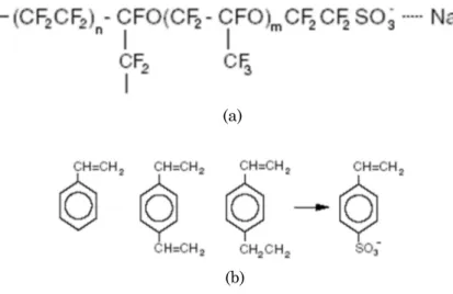
Perfluorinated alchenes: polymers with short side-chains termi-nated by ionic groups (typically sulfonate or carboxylate SO3- or
COO-) for cation exchange or ammonium cations for anion
ex-change (Figure 1.1a). The large polymer backbones determine their mechanical strength. Short side-chains provide ionic groups that interact with water and the passage of appropriate ions. Styrene/divinylbenzene-based polymers: in these polymers the
ionic groups have been substituted from phenyl rings where the nitrogen atom is fixed to an ionic group. These polymers are highly crosslinked and are rigid (Figure 1.1b).
In perfluorinated sulfonic acid polymers there are relatively few fixed ionic groups. They are located at the end of side-chains so as to po-sition themselves in their preferred orientation to some extent.
(a)
(b)
Figure 1.1: (a) Chemical structure of a Perfluorinated sulfonic acid polymer; (b) Chemical structure of Styrene/divinylbenzene-based ion exchange material.
Therefore, they can create hydrophilic nano-channels, so-called cluster networks.
There are several commercial ion exchange materials manufactur-ers; the most popular products that have been used for IPMCs fabrica-tion are: Neosepta® from Tokuyama, Flemion® and Selemion® from
Ashai Glass, and Nafion® from DuPont. Among all ionic polymer films,
the most used is Nafion® 117 from DuPont, which is a
perfluorosul-fonate polymer (the chemical structure is reported inFigure 1.2). In par-ticular, it is a copolymer of Tetrafluoroethylene and Sulfonyl Fluoride Vinyl Ether containing as fixed group the –SO3- group while M+ is the
positive ion (cation) that is free to move. M+, as furnished by the farm, is
H+but it can be substituted, by chemical processing, with Li+, Na+etc.
The most popular way of plating the polymer is an impregna-tion/reduction process that results in a conductive metal electrode on the surface of the polymer [3]. This process replaces the cationic groups of the polymer with a conductive metal. A reduction agent allows to form a network of metal particles on the surface of the polymer [4].
Because of the presence of the metal deposited on the surface of the polymer to facilitate electrical signal transmission to and from the pol-ymer, they are often referred to as IPMC (Ionomeric Polymer-Metal Composite). In literature they are also called ICPF (Ionic Conducting Polymer Film), IPT (Ionic Polymer Transducer) and IMPC (Ionic Metal-Polymer Composite).
In the 1990s, interest in ionic polymer transducers increased and the material was studied for its actuation and sensing capability
1.2. IPMC Actuating and Sensing Mechanism
Ionic polymers have inner ionizable groups that have the properties of dissociate in a variety of solvent media and movement in the molecular net generating a strong electric field (~1010V/m).
The -SO3-group is the fixed group in the polymer matrix of Nafion®
while the cation is free to move. Cations and anions move in opposite di-rections when a voltage is applied to a simple electrolyte and, therefore, no energy is transferred from the molecular network to the solvent, and no solvent molecule is carried. Instead, in the polymeric membrane mentioned earlier on, the solvent molecules can be parasitically carried by the free ions. Then it is clear that the deformation of an IPMC actua-tor is strictly linked to the charge migration inside it.
When an external voltage is applied across the thickness of the membrane, mobile cations will move toward the cathode. Moreover, if hydrated sample is considered, the cations will carry water molecules with them [5]. The cathode area will expand while the anode area will shrink; consequently the polymer will bend toward the anode. Cations with a high hydration number will produce greater deformation than cations with a low hydration number. An example is the case of the Lithium ion of which the hydrated volume is far bigger than either H+
or Na+[2]. For this reason in motion-related applications, the Hydrogen
ion of the Nafion® molecule can be purposefully substituted via an ion
exchange process with Na+, Li+etc.
The previously described phenomenon is known as water pumping. The cathode area expands while the anode area contracts. Consequent-ly, the polymer will bend toward the anode and, of course, the larger is the number of parasitically carried water molecules, the higher the de-formation effect will be (Figure 1.3). Water pumping is not the only phenomenon involved in the bending deformation when the IPMC is subjected to an electric field. Indeed, the two deposed metallic layers amplify the deformation by adding a Coulombian effect due to the inter-action of the charges.
Figure 1.3: Schematic diagram of ion transport in IPMCs
After deposition, the metallic ions scatter everywhere through the surface regions of the polymer because of the latter porous structure, and then they are reduced to their metallic atoms: the result is the for-mation of dendritic electrodes [5]. Moreover an external voltage will produce the accumulation of opposite charges on the two electrodes so the charges will interact with fixed anions in the polymeric bulk; these two effects are schematically shown in Figure 1.4. It is interesting to note that the interaction will be attractive for one electrode and repul-sive for the other. This effect is responsible for a further bending defor-mation due to the differential contraction–expansion of the strip’s ex-ternal fibres. Dendritic electrodes act as if the charges were concentrat-ed at their ends.
Figure 1.4: Interaction of charges within the IPMC membrane
The interaction with fixed and mobile ions of the network occurs on-ly close to the upper and lower surfaces of the strip.
When a constant voltage is applied, the gradient of water concen-tration causes a back diffusion of the water molecules that, in turn, is responsible for the relaxation of the membrane and the production of a residual deformation . As a consequence, IPMCs are not able to main-tain large constant deformations [6].
Water back diffusion is not the only cause of the membrane perfor-mance degradation over time. One must also consider that water tends to escape from the membrane both because of evaporation and of water electrolysis. Continuous membrane hydration has to be provided if con-stant performance is required.
The sensing capability has been demonstrated by measuring the in-verse performance, i.e. the voltage produced by the transducer when a deformation is forced [4]. The relationship between induced current in the polymer has been shown to be proportional to the mechanical de-formation [2].
A parameter that quantifies the sensing performance of the polymer is the electromechanical sensitivity of the material. In 2003, Farinholt et al [5] measured the sensitivity of Nafion® when a bending, shear, or
tensile force was applied. The material was found to be most sensitive to an imposed bending force.
The bending sensitivity of the material is dependent upon several factors. The frequency of the applied force, the length of the transducer, and the ionic form of the material has an effect on the electrical re-sponse of the polymer [6]. A comparison of the polymer with different cation clusters in the material indicates that the bending sensitivity in-creases with the ionic size of the material.
1.3. IPMC Modeling
Researcher involved in the study of IPMC adopted different modelling approaches so that a number of models have been proposed in the liter-ature. Currently there are three modelling approach for IPMCs: black box models, white box models, and grey box model [7], [8], [9].
The first (black box modelling) offers the least amount of insight into the fundamental mechanisms and is referred to as the black box model. This modeling technique provides a purely empirical model of IPMCs obtained through a series of curve fits based on experimental data [10], [11]. The first black box model of IPMCs was developed in 1994 by Kan-no et al. [10]. Their model, shown in Eqn.(1.1), offers nine fit parameters that can be used to fit experimental results.
F Ee De Be Ae Y t t t t (1.1)
They found that the parameters could not describe each excitation level, thus making the model dependent on both sample geometry and excitation voltage.
Xiao and Bhattacharya [11] also proposed a black box model of the ionic polymer transducer, focusing on the curvature of the IPT sample as it evolves with voltage and time. Their model is shown in Eqn (1.2):
V dt d v 1 (1.2) where
is the curvature of the sample, v is the saturation curva-ture per volt,
is the time constant, V is the applied voltage and t is the time variable. Interestingly, their development begins with more of an electrostatics development, however when placed in the reducedform used to model the macroscopic response of the IPT, they revert to a phenomenological model of the eigen-curvature.
This kind of models was first developed when there was very little knowledge of ionic polymer dynamics but a need for a model able to es-timate the IPMC behavior for various applications was largely reported.
The second type of models – called white box models, or physical models – rely on the underlying physical mechanisms of the IPMC to develop a system of equations that fully describe the material response [12], [13], [8]. These type of models attempts to describe the underlying microscopic physics and resulting transducer response. These models are not usually well suited for engineering applications because of the complexity of the resulting equations. Nemat-Nasser and Li [12] pro-posed a micromechanics model based on coupled three dimensional field equations. The constitutive parameters in the model are estimated based on the microstructure of the transducer using micromechanics. Nemat-Nasser and Li [12] proposed that the cations in the transducer migrate under an applied field and the anions that are attached to the backbone of the polymer move in an attempt to rebalance the local charge, this electrostatic motion creates the motion of the polymer and water migration and hydrostatics are secondary phenomena. This ex-planation of actuation is much different than the treatment of Tadokoro et al. [8], where the water migration was the primary cause of motion. Nemat-Nasser and Li [12] explain sensing in ionic polymers by the stress created by motion displaces the charge centre of the ionic cluster and the resulting dipole creates a voltage across the electrodes of the transducer. The equations needed to describe an ionic polymer trans-ducer in this model are much more complicated than is desirable for en-gineering applications of ionic polymer transducers. Since then, Nemat-Nasser has focused on the micro-mechanics associated with the phe-nomenon of actuation in ionic polymers [13]. Another example of white-box model is the model proposed in Tadokoro et al. [8]. This model is based on the relationship between three transducer properties, electri-cal, stress generation, and mechanical. Tadokoro et al. [11] proposed that a voltage applied to the transducer causes mobile cations to move from the anode (positive) to the cathode (negative) side of the
transduc-er, pulling water with along too. This water distribution causes the swelling of one side and the shrinking of the other, creating a curvature of the sample. Removal of the voltage redistributes the cations and pulls water again causing a motion in the opposite direction as the initial mo-tion. This model results in a system of coupled partial differential equa-tions that can be simplified and solved. The equaequa-tions are composed of relationships between physical and chemical parameters not well un-derstood or directly measurable. They did however show good correla-tion between measured data and predicted mocorrela-tion.
These two types of models both have drawbacks from an engineer-ing design standpoint. The first type lacks the scalability and physical relevance of terms, the second lacks simplicity and macroscopic rele-vance of the terms and equations involved. The ideal design model would consist of easily obtainable material properties and easily meas-urable transducer dimensions.
The third approach is considered the more enlightening grey box modeling. Still based somewhat on empirical data, grey box models combine fundamental physical laws with empirically derived parame-ters to describe IPMC electromechanical conversion. The empirically de-termined parameters often correspond to processes or mechanisms that are not as well understood or too complex to be incorporated into the grey box models [7], [9], [14], [15], [16].
The first of these grey box models was proposed in 1996 by Kanno et al. [14] in which he divides the model into two subsections: the electrical and the stress generation stages. Using an equivalent circuit model of the IPMC, Kanno et al. develop a relationship that describes the electri-cal current that is developed from an applied voltage. This portion con-stitutes the electrical stage whose output, the current, represent the in-put to the stress generation or mechanical stage of the model.
Work by De Gennes et al. [7] relies on a model formulation that has the potential to describe both sensing and actuation responses, however their consideration of only steady-state results does not account for the transient field developed in sensing. Their model is based upon linear irreversible thermodynamics and relates the flux terms of electrical and water current to the driving forces of electric field and water pressure.
While offering a very concise representation of the system, deGennes et al. [7] unfortunately do not compare their predictions with the meas-ured performance of IPMCs.
Another grey box model has been proposed by Paquette et al. [17]. The authors continue along the development of de Gennes et al. [7], pre-senting an equivalent electrical circuit of the IPMC that characterizes the upper and lower electrode surfaces as well as the bulk polymer membrane. This model assumes that the membrane is purely capacitive and that the upper and lower electrodes exhibit RC characteristics. The model enables Paquette et al. [17] to model the current to voltage rela-tionship in an equivalent circuit form. The concept is then integrated in-to the irreversible thermodynamics model of de Gennes et al. in-to provide predictive capabilities for the blocked force response of the IPMC.
Newbury [9] and Newbury and Leo [15] propose a linear two port model that can be used for modelling both actuation and sensing prop-erties of a cantilever actuator or sensor. The energy conversion between the electrical and mechanical domains can be represented using an ide-al linear transformer where the electric quantities are on one side of the transformer, and the mechanical quantities are on the other side, as shown in Figure 1.5
The model proposed in Newbury [9] and Newbury and Leo [15] pro-vides a linearly coupled set of equations that allow scaling of transduc-ers and their performance prediction without having to redetermine pa-rameters in the model.
The terms in the equations contain measurable macroscopic physi-cal and electriphysi-cal properties of the transducer as well as its geometry. Material parameters include the Young modulus, density, and electrical permittivity. This allows the scaling of transducers without having to redetermine coefficients in the equations. This model allows the predic-tion of various input-output relapredic-tionships and was validated for differ-ent transducer sizes for a frequency range of up to 20 Hz. The model does not try to explain or incorporate the fundamental phenomena with-in the transducer but rather provides an engwith-ineerwith-ing model useful with-in the design and application of ionic polymer transducers. One of the limi-tations with this model is the relatively low frequency range of valida-tion; higher frequency exploration has not been performed. Using a sim-ilar approach, Bonomo et al. [16] developed a model able to predict also the nonlinearities in the input absorbed current, introducing two diodes, as shown in Figure 1.6. These diodes are described by adapting the Shockley ideal diode equation.
Figure 1.6: The equivalent electrical circuit for an ionic polymer metal composite based actuator proposed by Bonomo et al
The mechanical response of the actuator is induced by the current passing through the branches R2-C2, R3-C3, reflecting the capacitive nature of IPMC.
Although numerous possible applications of ionic IPMCs in under-water environment, few models have been proposed in the literature for such environments.
In the next section a literature review about the possible applica-tions is reported.
1.4. IPMC Applications
The most attractive feature of EAP materials is their ability to emulate biological muscles with high fracture tolerance, large actuation strain and inherent vibration damping. EAP actuation similarity to biological muscles gained them the name "Artificial Muscles" and potentially can be used to develop biologically inspired robots. The limited force actua-tion of current EAP is constraining the practical applicaactua-tions that can be considered. Since EAP can be used as actuators that are light, com-pact and driven by low power, it is possible to take advantage of their resilience and fracture toughness to develop space applications, and in general applications in which high force are not required, as those pro-posed in this thesis.
In the following some potential applications realized by using IPMCs materials in the biomedical and industrial field are reported.
Microgrippers are essential tools in industrial processes. An inte-grated microgripper system, which can be easily implemented with any platforms operated with objects having a wide range of sizes and shapes, will have a great impact on optics manipulation, micro-electro-mechanical systems (MEMS), fiber-optics assembly, biomedical manipulation, and semiconductor manufacturing. K. S. Yun in his dis-sertation proposed, a micro gripper realized with IPCM and based on a specific control scheme. It will have significant applications including picking-and-placing micro-sized objects or as medical instruments. The precise manipulation of this three-finger gripper was successfully demonstrated with experimental closed-loop responses. A picture of the realized gripper is shown in Figure 1.7.
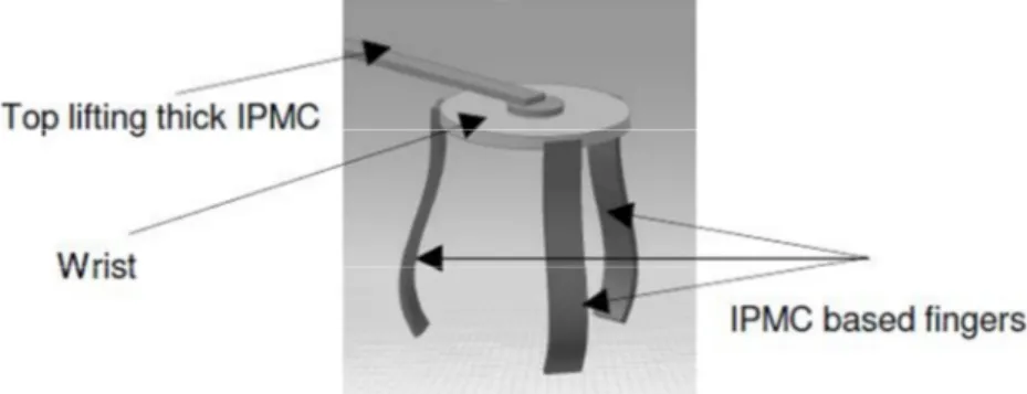
A more recent version of micro gripper realized with IPMC has been proposed. More specifically a remote center compliance (RCC) device that controls micro assembly operations [2], [12], [13], [18], [19], [20], consisting of a micro gripper with manipulation arm, has been realized by using 4 IPMCs strips [21]. The micro gripper consists of three IPMC fingers linking to the wrist and a single IPMC strip used as flexible low force robotic arm, as shown in Figure 1.8. The system allows lifting mi-cro object with small alignment in either position or orientation
inde-pendently. Insertion depth decrease with alignment angle and increase with applied voltage, as shown inFigure 1.9.
Figure 1.7: CAD model of RCC based micro gripper using IPMC
Figure 1.9: Performance of insertion depth of micro robotic arm and voltage A lot of underwater robot that involve IPMC as actuator have been proposed in literature, being these materials suitable to work in aque-ous environment. One of the first robot proposed is a robot that mimics rajiform swimming by undulating motions of pectoral fins. The realized prototype, showed in Figure 1.10 has two pectoral fins, composed of two IPMC sheets connected by a plastic foil. The tests confirmed that the fins are able to generate thrust and move the robot forward.
A more recent version of this model has been proposed by M. Yamamura et al. and it is shown in Figure 1.11. From the figure it is possible to notice that 8 IPMC strips are used for each fin. A simple traveling wave input generates propulsion of the fins.
In Figure 1.12 another robotic fish design is presented [2]. This ro-botic fish, equipped with a tail fin made from a single piece of IPMC ma-terial, has demonstrated that such a structure is feasible for mimicking biological fish locomotion.
Figure 1.11: Aquatic robot with 8 IPMC strips for each fin
Furthermore, the noiseless propulsion is attractive in nature. A maximum speed of approximately 2 m/min was achieved under an ap-plied voltage of 2 V.
Micropumps are devices that can be easily realized by using IPMC sheets. Bellows pumps can be made by attaching two planar sections of slightly different sizes of IPMC sections and properly placing electrodes on the resulting cavity. This permits modulation of the volume trapped between the IPMCs. The applied voltage amplitude and frequency can be adjusted to control the flow and volume of fluid being pumped. IPMC diaphragmpumps can also be made in various ways. Single or multiple IPMCs can function as the diaphragms that create volume displace-ment.
Figure 1.12: Robotic fish equipped with a single IPMC tail fin
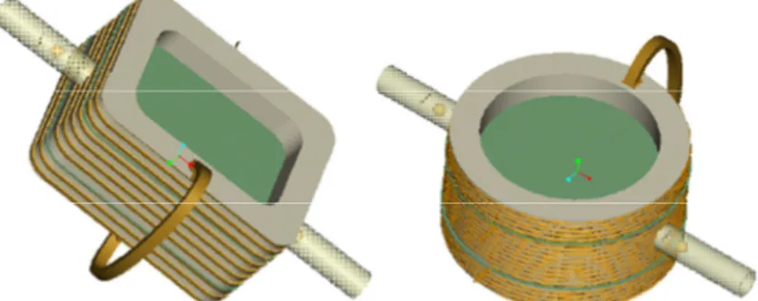
In Figure 1.13 a miniaturized double-diaphragm pump constructed of IPMC is shown. Such a pump produces no noise and has a controlla-ble flow rate in the range of a few microliters per minute. These pump systems can also be useful for biomedical applications. For example, each includes a pumping chamber having an anterior end attached to an implantable influent conduit in eye. In the case of an ocular pressure control device, the influent conduit is inserted into the anterior chamber of the eye. A flexing ionic polymer conductor composite IPMC artificial muscle functions as the primary actuator. The posterior end of the pumping chamber is connected to an effluent or drainage conduit, which may drain bodily fluids or dispense drugs to an area of the body. Figure 1.14 depict various configurations of such mini diaphragm pumps with rectangular and circular chambers.
Figure 1.13: A photograph of the fabricated double-diaphragmpump. The size of the IPMC is 1 mm width × 5 mm length × 0.2 mm thickness [2].
Figure 1.14: Perspective view of two (rectangular and circular chamber) double-diaphragm mini-pumps equipped with IPMC muscles and an inductive
receiving coil
A low cost and reliable IPMC actuator applicable to the develop-ment of disposable active cardiac catheter was designed and fabricated in [22] (Figure 1.15). An empirical model of the IPMC actuator for aque-ous manipulation was constructed. The model consisted of a fourth-order transfer function, a nonlinear gain and a time-delay term. Its pa-rameters were varied with driving potential, operating time and fre-quency. With the nonlinear compensation method proposed, the model was linearlized and the actuator performed well under the conventional PID closed-loop controller in bending angle control experiments.
Figure 1.15: IPMC fpr the realization of an active catheter systems
2. Ionic Polymer - Polymer Composites (IP2C)
As mentioned above IPMCs are constituted by an ion exchange perfluor-inated membrane, coated on both sides with a metallic electrode, gener-ally a noble metal such as platinum or gold [1]. These metals are char-acterized by high cost and require complex deposition techniques in or-der to obtain the electrodes. For the reasons mentioned above, all-organic transducers, with electrodes realized by using all-organic conduc-tors [23], [24], [25], [26], [27], named ionic polymer–polymer composites (IP2Cs), have been introduced.
This new class of transducers exploits polymers that are becoming available and that are characterized by high conductivity values. They have already attracted researcher’s interest in various application do-mains from electronics to robotics or biochemistry organic conductors.
All-organic actuators and sensors have been realized based on a flu-orocarbon membrane (i.e. Nafion 117), covered in both sides by a con-ductive material.
The basic procedure in fabricating IP2Cs comprises five main steps:
1. A sandblasting step is required to ensure mechanical adhe-sion of the organic conductor (since rough samples guarantee better adhesion properties)
3. Chemical cleaning (by boiling in HCl (2.5 M) and, then, wa-ter).
4. The organic conductor is deposited using techniques such as spin-coating, dip-coating, spin-casting and printing tech-niques
5. After solvent evaporation, the obtained samples are im-mersed in deionized water.
The deposition techniques of organic materials from solutions are relevant due to their low manufacturing cost. The conducting materials usually used to realize the IP2Cs are listed in Table 1.1.
Table 1.1: Conducting materials
Organic Con-ductor
Trade Name Producer
PEDOT:PSS Baytron®PH 500 H.C. Starck
PEDOT:PSS Baytron®P HC V4 H.C. Starck
PEDOT:PSS Orgacon™ EL-P 3040 AGFA
PEDOT:PSS Orgacon™ EL-P 5010 AGFA
PANI Polyaniline
(Emerald-ine Base) MW- 50000 Sigma Aldrich
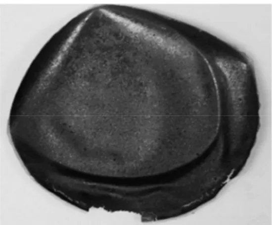
Figure 1.16: Samples prepared by drop-casting technique.
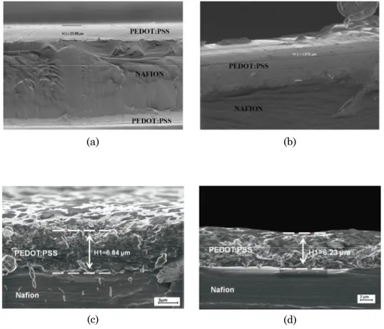
In Figure 1.17 four SEM images of two IP2C sections are reported.
More specifically, figures (c) and (d) show two samples with Orgacon®
EL-P 3040 electrodes, whose thickness is about 6–7 μm, while the thickness of the Nafion® 117 membrane is 178 μm. It is possible to
ob-serve that the PEDOT:PSS surface is highly inhomogeneous. Moreover, the electrode thicknesses of two devices with the same organic conduc-tor can be different because of the conducconduc-tor deposition process, as shown in Figure 1.17.
In the following of the thesis both IPMC and therefore IP2C
(a) (b)
(c) (d)
Figure 1.17: SEM images of a section of dip coated PEDOT:PSS film.
3. Experimental Set-up
Analysis of the behaviour of the proposed systems usually involves three main stages:
1. design and construction of an experimental setup able to electrify the membranes under study and reproduce the environmental conditions
3. processing of the collected resultant digital signals to extract the particular information required
The research described below, depends on the use of some external devices both to digitize and analyse the signals. Among the most im-portant can be mentioned:
Distance laser sensor 12U6460/S35A Baumer Electric. Shaker (Tira TV 50009)
copper electrodes realized on a printed board. (Figure 1.18)
Figure 1.18: copper electrodes realized on a printed board
There is now a very wide range of ADC cards available for operation in PCs for the acquisition of data The systems used is based on the Na-tional Instruments data acquisition card model NI-PCI 6052E.
The interactions with the users were guaranteed thanks to the use of a dedicated interface developed in the Labview® environment.
In practice, most of the experiments require purpose-designed soft-ware. These will include (see later) spectral analisys, system's transfer function calculation, estimation of the predicted signals for the systems under investigation.
The analysis of the signals obtained took advantage by using a PC-based systems with the software MathWorks Matlab®.
3.1. Conditioning circuitry
Considering IPMC and IP2C based systems, in an electrically view,
the critical point for these systems is not the high frequency, which in fact does not exceed 100 Hz, but the low level of the output signal. In fact, due to the small signal found, a specially designed signal condition-ing circuitry was realized.
Main characteristics of these circuits are an high gain and a low noise floor.
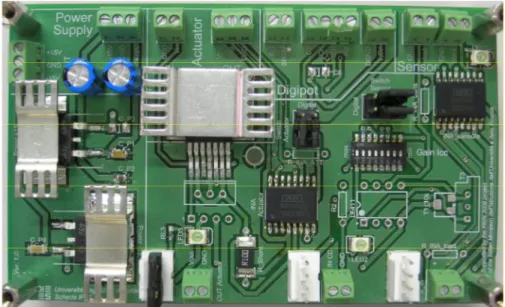
In
Figure 1.19the conditioning circuits for the IPMC actuator and
sensor are shown.
Figure 1.19: Real view of the conditioning circuits
3.1.1. Conditioning circuit of the IPMC sensor
Figure 1.20 reports the scheme of the circuit adopted for the estimation of the short circuit current of the IPMC sensor.
Figure 1.20: The scheme of the conditioning circuit of the IPMC sensor The sensor's conditioning circuit is a short circuit current amplifier. The IPMC sensor generates currents of the order of magnitude of micro-amperes. Consequently, in order to ensure the output voltages in the order of a few volts, the gain of the amplifier must be sufficiently high, approximately 106.
This gain is linked to the value of the feedback resistor R as shown in Figure 1.20.
The relation between the output voltage and the input current is given by Ohm's law.
VOUT= -RIin (1.3)
The presence of a gain so high imposes the necessity to adjust the amplifier offset. In fact, the presence of a DC component in the input signal could saturate the obtained output signal.
The operational amplifier used allows the offset adjustment through insertion of a trimmer appropriately positioned.
Bending a IPMC used as a sensor, by both sides with respect to the longitudinal axis both negative and positive, currents are produced. It is therefore necessary to use a dual power supply. A dual voltage ±15 V ensures that the output signal can be positive or negative following the direction which the IPMC is deflected.
3.1.2. Conditioning circuit of the IPMC actuator
Figure 1.21 reports the conditioning circuit adopted for the driving of the IPMC actuator along with the INA111 (instrumentation amplifier) for the estimation of the absorbed current of the IPMC actuator.
Figure 1.21: The scheme of the conditioning circuit of the IPMC actuator The conditioning circuit for an IPMC used as actuator must to be able to provide the suitable level of current, required for the proper functioning of the device.
During its normal operation, the IPMC actuator requires a voltage in the range [0, 2 V - 6 V]. The levels of current drained during the op-eration of the actuator are extremely variable and depend, as well as by the amplitude of the control signal, also by the dynamics of the external signal imposed.
In order to ensure the functioning of the IPMC actuator, even in ex-treme conditions a power operational amplifier OPA548 capable of de-liver a maximum continuous current of 3.0 A and 5.0 A of peak current was used.
A INA111 has been inserted into the circuit to measure the ab-sorbed current , it is able to detect the voltage drop, caused by the cur-rent absorbed by the actuator, on a shunt resistor R1 in series with the IPMC output.
Thanks to this voltage it is possible to trace the current that flows in the operational amplifier output
= (1.4)
where IOUTrepresent the output current value, Rshunt represent the
val-ue of the resistance in series with the amplifier output and GINA
1. Introduction
In the last years the use of cantilevers in rheological measurements of fluids has received a big attention [28], [29], [30]. Rheological applica-tion of small-size cantilevers proposed in literature was generally re-stricted to the measurement of liquid viscosity [31], while a priori and independent measurement or knowledge of the liquid density was re-quired, which restricts the utility of this technique.
Sader et al. developed a theoretical framework [32], [33] for the descrip-tion of cantilever vibradescrip-tions in viscous fluids. That theory can be ex-ploited for the simultaneous measurement of both density and viscosity of fluids [31]. Here a system is proposed that exploits the electro-mechanical characteristics of a vibrating system at its resonance fre-quency to determine the density and the viscosity of the fluid in which it is immersed. In particular, use the frequency response of a cantilever immersed in a fluid, allows to estimate the rheological properties of the fluid. More specifically, a device that uses the frequency response of two IPMC strips fixed together in cantilever configuration in order to esti-mate both the density and viscosity of liquids is proposed.
All the properties mentioned above make IPMCs suitable for the viscometer envisaged here.
Thanks to the use of an IPMC strip as an actuator and an IPMC strip as a sensor, the viscometer is very simple in structure and
opera-tion modality and will be easy to be micro manufactured; moreover, it requires a low-voltage supply and it is lightweight.
The considerations reported above show the interesting properties of the IPMC based small scale viscometer.
More specifically, the possibility to use IPMCs for viscosity and density measurements of sucrose solutions is demonstrated. Sugar solu-tions are valuable test systems for such devices, since many biological liquids contain a remarkable amount of sugar [34].
In this work were realized two different versions of the viscometer. The first version of the measuring system involved the use of an IPMC actuator, set in vibration under the effect of an external electrical force, and a commercial laser sensor [35], used to measure the corre-sponding deflection of the vibrating system. It was, evidently, an inter-mediate system, intended to verify the operating principle.
The second version of the measuring system is based on the use of two IPMC membranes, respectively used as actuator and sensor. The second IPMC strip was added in order to measure the deflection [36]. Such a system will allow to exclude the laser and obtain a device, based only on polymeric materials, capable of measuring the density and vis-cosity of fluids.
2. The first version
The proposed device uses the electromechanical characteristics of a vi-brating system at the resonance frequency, to determine the density and the viscosity of the fluid in which it is immersed [31].
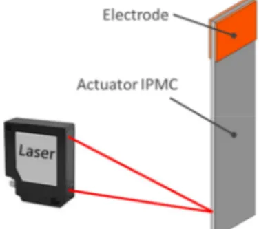
The system, in its first version, involves the use of an actuator IPMC set in vibration. The deflection produced is measured by using a laser sensor [35].
The vibration is produced by applying a sinusoidal voltage signal, that sweep across the interested frequency bandwidth, to the electrodes of the IPMC actuator which, subjected to electric stress, deflects in re-sponse to the imposed signal [37], [38].
To measure the amplitude and frequency of the deflection produced by the actuator the distance laser sensor 12U6460/S35A Baumer Elec-tric was used.
Figure 2.1: The sensing element of the device in his first version
2.1. The Model
In this section the IPMC model used to realize the viscometer is intro-duced. In literature a number of models of IPMC actuators has been re-ported [38], [39]. These models describe the behaviour of the IPMC in the absence of any fluid (i.e. in vacuum), while the modelling of an ac-tive beam immersed in a viscous fluid in not so much investigated. An analytical model for IPMC actuators immersed in a viscous fluid [37] was used to design the viscometer. The modelling approach is based on the hydrodynamic function concept for the case of an active IPMC beam with rectangular cross-section.
The motion equation of the IPMC actuator in a viscous fluid is obtained by adding to the equation ruling motion in vacuum, the force [40]
h
V F
g
g (2.1)
where the term gV represents the fluid damping force and the term Fh
represents the inertial force, due to a skin of fluid dragged by the canti-lever in its motion, that corresponds to an additional mass.
The term gVcan be expressed by t w C gV V (2.2)
where C is the fluid damping coefficient, w is the beam deflection and tV
is the time. The term Fhcan be expressed by
2 2 t w m Fh a (2.3)
where ma is referred to as the added mass that is proportional to the
displaced mass of the fluid, md.
f m d m a C m CV m (2.4)
where Cmis the added mass coefficient, V is the volume of the immersed
body, and ρfis the density of the fluid.
The system's equation of motion can be solved by knowing the value of the two constants Cm and CV. In particular, the value of these constants
can be analytically calculated considering the case of a bar with a cylin-drical section and infinite length, and taking into account the Navier-Stokes equations [41], [42].
For small values of the amplitude of the oscillations, and in conditions of oscillatory motion stationary, (w=w0sin(ωt)), the equation (2.1) can be
rewritten as [40]
= − − = [ (Γ) + (Γ) ] (2.5)
Cmand CVcan be computed by using the real and imaginary parts of the
complex function :
Re m C
dIm V m C 2 4 b md f (2.6)where
is the hydrodynamic function and b is the width of the IPMC cross-section.The exact expression of the hydrodynamic function is known in the lit-erature in the case of a beam with circular cross section and takes the following form [32]
Γ ( ) = 1 + 4 − √
√ − √ (2.7)
where K0and K1are the modified Bessel functions of the third kind,
and Re is the Reynolds number, which is
= 2 (2.8)
The parameter b represents the dominant dimension for the de-scription of the motion in the fluid ( the diameter for a beam with circu-lar cross-section, the width for a beam with rectangucircu-lar section).
In the case of membrane with rectangular cross section, the hydro-dynamic function can be obtained starting from the expression (2.7) and using a correcting term Ω(ω)
Γ ( ) = Ω( )Γ ( ) (2.9)
the expression of the term Ω(ω) can be found in the literature [32]. The function Γ(ω) thus obtained is valid for values of the Reynolds number in the range 0.1 ≤ Re ≤ 1000. However, for the operating condi-tions envisaged for the proposed device, this parameter varies in an in-terval much more limited [37] and it is possible to use simplified expres-sion of the hydrodynamic function [43]. The real and imaginary parts of the proposed hydrodynamic function are, respectively,
b c c1 2 Re
3 4 2 Im b c b c (2.10)where c1, c2, c3and c4are suitable parameter and δ is the length giving
the thickness of the thin viscous layer surrounding the cantilever in which the velocity has dropped by a factor of 1/e [43] [44]:
f 2 (2.11)
where ηis the viscosity. The approximated expression (2.10) is obtained by fitting the corresponding complete form for a fixed IPMC actuator shape, in the frequency range considered. Substituting (2.10) in (2.6) the following expressions for coefficients Cm and Cv are obtained
. 2 4 3 2 1 b c b c m C b c c C d V m (2.12)
The hydrodynamic function can be used to rewrite the motion equation of the IPMC actuator by taking into account its interaction with the flu-id
f
x t t t x w b C A t t x w C x t x w YI f m c v , , 4 , , 2 2 2 4 4
(2.13)The mode summation method [45] can be used for the solution of (2.13). More specifically the motion of the IPMC actuator can be estimated as
c j t i i i f i f i d c t j i i i f i f i d c f e V Y w h d x L H m A e M x L H m A t x w 0 2 0 2 2 ) ( 1 1 ,
(2.14)Where:
f i f i f i i j H 2 1 1 2
12 1 f i m c f i f i hC b
f i c f i v f i A C 2 . (2.15)and M0 is the module of the bending moment, produced by an
ex-ternal voltage stress with V0as module, through the coupling term da()
[39].
In the neighbourhood of each resonant peak, the frequency response of a cantilever beam, when the quality factor Q greatly exceeds unity, can be approximated as that of a simple harmonic oscillator [31]. The ampli-tude frequency response f()
i w is given by
2 2 2 2 2 0 ) ( Q W w r r r f i (2.16) where W0denotes the amplitude at the frequency ω = 0, Q is the qualityfactor defined as:
) ( ) ( 4 2 r i r r b Q (2.17)
and ω and ωrare the radial frequencies and resonant frequency,
respec-tively.
For the cantilever calibration and measurement of rheological parame-ters, equations (2.15) and (2.17) have been used.
Quantities in (2.16) and (2.17), relevant to describe the IPMC system in resonant condition, can be used for the measurement of the fluid's rheo-logical parameters. In particular, although the equations (2.16) and (2.17) are applicable to all system's modes, the amplitude obtainable
de-creases with the order of the mode. For this reason, in the following the study of the system and the estimation of the parameters of the fluid will be done by using the processing of data relating to the first mode.
2.2. Experimental set-up
A measuring system, shown schematically in Figure 2.2, was realized for the experimental investigation of the prototypes, it allows to apply an electrical signal to the actuator and to measure the deflection ob-tained.
The study of the behavior expected also to the identification of the electromechanical model's parameters of the of the IPMC strip view as actuator, it means identify the system.
Figure 2.2: Measuring system realized for the experimental investigation The signal is synthesized by a function generator and trought to a driver circuit, which has the purpose of providing adequate current to the actuator (which may even reach the hundreds of milliamps), is ap-plied to a couple of elecrtrode that have the dual purpose of clamp and electrify the IPMC strip
For the realization of the circuit have been used two amplifiers: an OPA 547, in the configuration buffer, which has the
pur-pose to supply the requested current to the membrane an INA 111 used to measure this current.
The measuring system also includes a laser distance sensor (Baumer Electric 12U6460/S35A), for detecting the deflection of the de-vice in his free end point.
The signals were acquired by using a National Instruments data acquisition card (NIPCI_6052E).
Experiments were carried out using various test fluids, in particu-lar distilled water and sucrose solutions with different concentrations of sucrose.
The choice fell on sucrose solutions because their rheological char-acteristics are known and easily available in the literature, also are so-lutions that have a significant relevance, from the application point of view, in biological field.
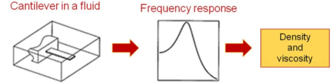
The procedure adopted for measure density and viscosity of the flu-ids is shown in Figure 2.3.
The system is put in vibrational motion, by applying a sinusoidal voltage input to the conditioning system, this signal has a constant am-plitude and frequency linearly increasing with time.
Both the electrical stress and the signal provided by the distance sensor were collected in order to estimate the cantilever's frequency re-sponse.
The acquired data are then processed, by using a MATLAB®
pro-gram, in order to estimate the value of the resonant frequency of the system and the quality factor Q. These parameters are then processed to estimate the values of viscosity and density.
2.3. First Version Results
In order to verify the operating principle of the viscometer, a set of measurements were performed by using sucrose solutions with different concentrations.
In particular, measurement campaigns were carried out by immers-ing the actuator IPMC in distilled water and sugar solutions with mass concentrations, normalized with respect to the condition of saturation, respectively equal to 0.3, 0.6 and saturated solution.
Figure 2.4 shows a comparison of the modules of the predicted fre-quency responses and the frefre-quency responses obtained from data ac-quired.
Figure 2.4: Module of the frequency response of the expected behavior and module of the frequency response of the first experimental version of the viscometer, immersed in solutions with different density values: a) distilled water, b) sugar solution 0.3, c) sugar solution and 0.6) saturated sugar solution.
As predicted by theory, the probe has a behavior related to the ma-terial that surrounds it.
From inspection of Figure 2.4 it is possible to note how the variation of both the values of the resonant frequency and the amplitude of the resonance peak, depending on the characteristics of the fluid in which the device is immersed.
In particular with the increasing of the concentration of sucrose in the solution, there is a corresponding lowering of the resonance fre-quency and a reduction of the value of the resonance peak.
Furthermore it is possible to assert that the processing of the data recorded by the measuring system has provided results in accordance with the estimates obtained from the analytical model previously re-ported.
Figure 2.5 and Figure 2.6 shows the experimental values of the res-onance frequency for the first mode and the quality factor Q and the re-spective theoretical values, predicted at the computer by using algo-rithms based on the model previously described, in function of the solu-tion's sucrose concentrations.
Also for these parameters the processing of experimental data has led to a good agreement between the estimates and the expected values from the models adopted.
Figure 2.5: Experimental and predicted frequency response in
differente sucrose solutions.
Figure 2.6: Experimental and predicted quality factor Q of the
IPMC actuator in solution with different sugar concentrations.
3. The Second Version
The system described in the previous paragraph represents an interme-diate prototype aimed at demonstrating the possibility to realize a vis-cometer using IPMC transducers. Nevertheless, that prototype was in-tended as a proof of concept and was of no practical application.
The first version lacked of an embedded sensor that would allow the measurement of the deformation of the vibrating actuator that allow to use the system in applications of real interest [36].
The device described in this section is, therefore, an evolution of the previous version, in fact, the laser distance sensor is replaced by a sen-sor IPMC [46].
The system is freed by external devices, such as the laser sensor to make the measurements, allowing the realization of a smart system, to-tally polymeric, able to provide directly an output signal, useful for the estimation of the rheological parameters of the fluid.
The sensing element of the proposed device is a multilayer beam realized superimposing an IPMC actuator and an IPMC sensor, as shown in Figure 2.7
Figure 2.7: The sensing element of the proposed device
The two membranes are completely immersed in the fluid and placed in a cantilever beam configuration
The IPMC actuator is used to impose a vibration to the whole system, by applying to its electrodes an appropriate driver signal. The IPMC sensor is attached to the actuator so that it is forced to follow the system deflection. An electrical signal is, therefore, collected at the sensor elec-trodes and is used to measure the amplitude and the frequency of the deflection.
This signal is collected and processed to perform the measurement of the deflection, the laser is eliminated and is substituted by the IPMC sensing element, although it will still be used in order to have an inde-pendent measure necessary to validate the system.
As in the previous case, from this information it is possible to obtain the values of the system's resonant frequency and its quality factor and from these to trace the rheological characteristics of the fluid.
Obviously, in this second case, it is necessary to introduce in the model of the measuring system also the model of the sensor, as will be better specified in the following.
3.1. The model
Even for this version are valid are quantities expressed by the equation (2.16) and (2.17), but for this application, in which is used an IPMC sen-sor as sensitive element of the device, it is necessary to process the out-put signal of the sensor, which is presents as a short-circuit current, to retrive the deformation of the system.
Figure 2.8: Conversion from the acquired signal to the real deflection The model of the IPMC sensors has been previously described in the introduction chapter. In particular, the law which binds MS, in the
fre-quency domain, the deformation δ(s), setted to the free end of an IPMC sensor, and the corresponding short circuit current i(s) is described by the following equation:
= ( )( ) = ∙ ( ) ∙ ∙ ∙∙ (2.18) where s is the Laplace operator, w is the sensor's width, t is the sen-sor's thickness, Ls is the point in which the deformation is applied (in
this case the point of contact with the actuator), Y is the Young's modu-lus of the sensor, ds(s) is the electromechanical coupling term.
About the electromechanical coupling term, the function that gave the best modeling resulted in the following form [46]:
(s) = ( + ) ∙ ( + ) (2.19) whose parameters were obtained in MATLAB through an algorithm of error minimization (see Appendix), the obtained parameters are re-ported in Table 2.1
Table 2.1: Values obtained for parameters characterizing the complex function d.
k (C s2N−1) α (Hz) β (Hz)
-8.62 e-002 87,5 7.37 e+008
In Figure 2.9 and Figure 2.10 the experimental and simulated fre-quency response of the device considering the tip deflection and the out-put current of the IPMC sensor respectively are shown. As it can be no-ticed from the figures also in this new configuration the model is able to predict well the device behaviour.
Figure 2.9: Experimental and predicted frequency response for the system, tip deflection in air. 5 10 15 20 25 30 35 40 45 50 55 0 0.02 0.04 0.06 0.08 0.1 0.12 0.14 0.16 Frequency [Hz] T ip d ef le ct io n [m m ] Simulated data Experimental data
Figure 2.10: Experimental and predicted frequency response for the IPMC sensor output current in air.
In a similar manner to that described for the first prototype, the current produced by the sensor, is used to estimate the deformation of the vibrating system and from this the value of the resonance frequency of the first mode and this corresponding quality factor Q. From these values it goes back to the rheological parameters of the fluid by using the equations (2.16) and (2.17).
Figure 2.11 shows how the predicted frequency response well fit the experimental frequency response for the IPMC sensor output current in water.
Figure 2.11: Experimental and predicted frequency response for the IPMC sensor output current in water.
5 10 15 20 25 30 35 40 45 50 55 0 0.2 0.4 0.6 0.8 1 1.2x 10 Frequency [Hz] C ur re nt [A ] Simulated data Experimental data 101 0 1 2 3 4 5 x 10⁻⁴ Frequency [Hz] F re qu en cy r es po ns e [m /V ]
3.2. Experimental set-up
The system adopted for the measurement of density and viscosity with this prototype is similar to the one used in the first version of the vis-cometer, the steps are shown Figure 2.12
Figure 2.12: The steps of the adopted method for the measurement of density and viscosity.
As for the first analysis in a previous system (used to validate the theoretical approach), an IPMC based cantilever system was immersed in a fluid. It was forced by using a suitable signal and a vibrating mo-tion was generated. The momo-tion is produced by an IPMC actuator that is actuated with a sinusoidal swept input voltage.
The vibration of the system was detected by using the sensing IPMC element and a current was generated. Acquired data were pro-cessed in order to estimate the cantilever resonance frequency value, Q factor, and therefore the fluid rheological parameters.
Therefore this second version differs substantially from the previ-ous for the addition of the IPMC sensor and the consequent presence of a current to voltage converter used as a conditioning circuit for the IPMC sensor, finally the system's deflection will then be a function of the obtained voltage. Even in this version is maintained the laser dis-tance sensor (Baumer Electric 12U6460/S35A), but with the aim of al-lowing the independent measure of the deformation of the vibrating sys-tem.
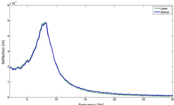
Figure 2.13 shows an example of how the deflection derived from IPMC sensor signal well fit the real deformation of the vibrating system measured by the laser sensor
Figure 2.13: Comparison of the measure of the deformation of the vibrating system provided by the laser sensor with the deflection derived from IPMC
sensor signal
The measurements were carried on using as testing fluids sugar so-lutions, as reported above.
The frequency response is measured and values of both viscosity and density of the fluid are derived. For the experiments a sample of IPMC 10 mm long, 3 mm wide was used.
3.3. Results
To perform the measurement campaign two membranes, as sensor and actuators, whose dimensions are shown in Table 2.2, have been used.
Table 2.2: Viscometer geometrical parameters
Length Width Thickness
Sensor 22 mm 1, 5 mm 0, 180 mm
For each campaign 20 repeated measurements were performed. In Figure 2.14 and Figure 2.15 the experimental and simulated fre-quency response of the device considering the tip deflection and the out-put current of the IPMC sensor are shown.
In particular in Figure 2.14 the points represent the single measures, the circles represent the average response and the continu-ous blue line represents the predicted response. This result has been achieved by immersing the device in deionized water.
The same schematization is true for Figure 2.15, that refers to the case when the device was immersed in a sucrose solution, 30% in mass.
F ig u re 2 .1 4: E xp er im en ta l a n d pr ed ic te d fr eq u en cy r es po n se f or t h e IP M C s en so r ou tp u t cu rr en t in w at er
F ig u re 2 .1 5: E xp er im en ta l a n d pr ed ic te d fr eq u en cy r es po n se f or t h e IP M C s en so r ou tp u t cu rr en t in a s u cr os e so lu ti on 3 0% in m as s
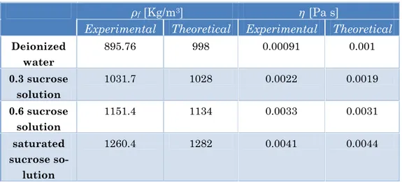
The model is able to predict well the behaviour of the system. The Table 2.3 shows some values of the rheological characteristics estimated using the proposed system and the corresponding values deduced from the literature.
Table 2.3: Experimental and theoretical density and viscosity values for differ-ent sucrose solutions
ρf[Kg/m3] η[Pa s]
Experimental Theoretical Experimental Theoretical
Deionized water 895.76 998 0.00091 0.001 0.3 sucrose solution 1031.7 1028 0.0022 0.0019 0.6 sucrose solution 1151.4 1134 0.0033 0.0031 saturated sucrose so-lution 1260.4 1282 0.0041 0.0044 4. Conclusions
The possibility to use IPMC transducers to realiza a viscometer has been described and experimentally investigated. The feasibility pf the proposed system has been verified for fluids with increasing densities and viscosities.The obtained results show the applicability of the pro-posed systems.
The system uses both acting and sensing IPMC to realize a smart system.
1. Introduction
Ferrofluids (known also as magnetic fluids) are a special category of smart nanomaterials, in particular magnetically controllable nanoflu-ids. These types of nanofluids are colloids of magnetic nanoparticles, such as Fe3O4, γ-Fe2O3, CoFe2O4, Co, Fe or Fe-C, stably dispersed in a carrier liquid [47], generally water or solvent, and covered with a thin polymeric layer, (surfactant) to prevent their agglomeration caused by Van der Waals forces [48]. These nanomaterials manifest simultaneous-ly fluid and magnetic properties. A magnetic field applied to a ferrofluid volume exerts a magnetic force which causes the alignment of the fer-rofluid particles in the direction of the field, modifying its physical prop-erties such as density and viscosity. Moreover, under particular condi-tions, a ferrofluid volume subjected to a magnetic force can behave like a mass connected to tunable equivalent spring whose properties can be controlled by modulating the driving magnetic field [47]. Ferrofluids are widely used in sensors and actuators, where generally a small volume is used as the inertial mass, or in biomedical devices for diagnostic and therapy [49].
The need for smart sensors adapting their characteristics to the specific application is continuously emerging. Combining performances of IPMC sensors and magnetic fluid properties it is possible to optimize
the sensor performances in terms of its operating range, sensitivity and frequency response.
Here a seismic sensor exploiting both IPMC and ferrofluid is de-scribed [50].
The device consists of an IPMC beam housed in a small vial, filled with ferrofluid, whose properties depends on the magnitude of an exter-nal magnetic field applied to the device. This approach allows for the implementation of an active tuning of the sensor specifications (such as operating range, frequency behavior and responsivity) by an external magnetic field, which can be claimed as the main advantage of the pro-posed strategy.
In the following Sections, the sensing methodology developed, the description of the sensor prototype and the experimental set-up are pre-sented, along with experimental results confirming the suitability of the proposed approach. Moreover, a possible form of device modeling is dis-cussed in order to predict the relationship between main sensor features and the external magnetic field.
2. The realized system 2.1. The working principle
A schematization of the seismic sensor is sketched in Figure 3.1. The device consists of an IPMC Nafion® membrane used as the sensing ele-ment immersed in a ferrofluid. The membrane acts both as the seismic mass and the transducer that converts the imposed inertial stimulus in-to an electrical signal.