PAPER
Nebulized jet-based printing of bio-electrical scaffolds for neural tissue
engineering: a feasibility study
To cite this article: Miriam Seiti et al 2020 Biofabrication 12 025024
View the article online for updates and enhancements.
PAPER
Nebulized jet-based printing of bio-electrical scaffolds for neural
tissue engineering: a feasibility study
Miriam Seiti1,2,4
, Paola Ginestra2
, Rosalba Monica Ferraro3
, Elisabetta Ceretti2
and Eleonora Ferraris1 1 Department of Mechanical Engineering, Campus De Nayer, KU Leuven, Belgium
2 Department of Mechanical Engineering, University of Brescia, Brescia, Italy
3 Department of Molecular and Translational Medicine,‘Angelo Nocivelli’ Institute of Molecular Medicine, University of Brescia, Brescia,
Italy
4 Author to whom any correspondence should be addressed.
E-mail:[email protected]
Keywords: neural tissue engineering, additive manufacturing, printed electronics
Abstract
In this paper we investigate the application of a direct writing technique for printing conductive
patterns onto a biocompatible electrospun-pyrolysed carbon-fibre-based substrate. The result is a first
study towards the production of bio-electrical scaffolds that could be used to enhance the promotion
of efficient connections among neurons for in vitro studies in the field of neural tissue engineering. An
electrospinning process is employed for production of the materials derived from the precursor
polyacrylonitrile, in which the embedding of carbon nanotubes
(CNTs) is also investigated.
Subsequently, the methodology of research into suitable parameters for the printed electronics, using
a commercial silver nanoparticle
(Ø
avg,particle size∼100 nm) ink, is described. The results show values
of 2
Ω cm for the resistivity of the carbon-fibre materials and conductive printed lines of resistance
∼50 Ω on glass and less than ∼140 Ω on carbon-fibre samples. Biocompatibility results demonstrate
the possibility of using electrospun-pyrolysed mats, also with embedded CNTs, as potential neural
substrates for spatially localized electrical stimulation across a tissue. In addition, the data concerning
the potential toxicity of silver suspensions are in accordance with the literature, showing a
dose-dependent behaviour. This work is a pioneering feasibility study of the use of the
flexible and versatile
printed electronic approach, combined with engineered biocompatible substrates, to realize
integrated bio-electrical scaffolds for in vitro neural tissue engineering applications.
1. Introduction
Every year neuro-degenerative diseases (e.g. Alzhei-mer’s, Parkinson’s) have direct consequences for millions of people. Nine out of ten individuals over the age of 80 years will probably suffer from a brain disorder, which account for ∼35% of all human diseases[1].
Because of the poor regenerative capacity of the central nervous system[2], neural tissue engineering
investigates the design and production of scaffolds to restore the functions of injured neural tissues[3].
Scaf-folds act as a means of mimicking the complex in vivo neural environment, focusing on different guidance cues such as molecular, electrical, topographical or chemical ones[2]. In the ideal case, a combination of
these cues will produce a synthetic fabric similar to the
natural extracellular matrix(ECM), which governs the physiology of neural cells[4].
Over the last century, a large number of bio-compatible materials were developed using several techniques. Boni et al[5] reviewed different natural
and synthetic polymers, with specifications aimed at emphasizing adhesion, growth, orientation, prolifera-tion and differentiaprolifera-tion of different types of neuronal and neural cells.
Among the techniques most often used to produce biocompatible scaffolds, electrospinning is well known to produce suitable scaffolds for adhesion, proliferation and extension of neurons[6]. This technique is able to
electrospin various materials including biodegradable, non-degradable and natural materials [7]. Its main
advantage is the ability to produce non-woven polymer mats consisting of nanofibres in a versatile, flexible and
RECEIVED 13 September 2019 REVISED 6 January 2020 ACCEPTED FOR PUBLICATION 30 January 2020 PUBLISHED 4 March 2020
affordable way [8]. Fibre diameters can range from
several nanometres to a few micrometres, and the possi-bility of controlling their desired viscosity and con-ductivity of the solution facilitates the production of engineered neural scaffolds. Specifically, electrospun nanofibres can be assembled into scaffolds by manip-ulating their morphology, alignment, stacking and/or folding behaviour [9]. As reported by Xie et al [10],
anisotropic fibre arrangements show a effective cues to direct and enhance neurite outgrowth than isotropic materials such as hydrogels. For instance, cell differ-entiation and enhancement of neurite outgrowth have been tested on aligned poly(L-lactic acid) nano/
microfibrous scaffolds [11]. In addition, neural
bio-electrical properties and synaptic activities can be modu-lated by material–neuron interactions, when substrates are also characterized by a high level of electrical con-ductivity. Hence, the embedding of conductive nano-materials in neural interfaces has also been found to promote efficient connections among cells and preserve normal or even enhanced neuronal activities, after stem cell differentiation. Among these materials, carbon-based nanomaterials such as graphenefilms [12],
three-dimensional graphene foams [13], reduced graphene
oxide with poly(3,4-ethylenedioxythiophene) (PEDOT) [14], carbon nanotubes (CNTs) [15], CNT ropes [16],
multi-walled CNTs (MWCNTs) [17] and MWCNTs
with a PEGDA polymer[18] have been explored for
these applications, with promising outcomes.
Bio-electricity mostly regulates cell behaviours and biological functions(cell adhesion, proliferation and migration) during tissue regeneration. The appli-cation of an electricalfield can support this process in in vitro applications [19]. In this context, neural
engineering aims to study neuronal networks using electrical stimulation(ES) impulses through the devel-opment of an interface between electronic devices and living neural tissue [20]. ES is indeed an efficient
approach to stimulate and record the activities of neural cells[21]. An applied electric field (or an electric
current) can influence the direction and proliferation of neurite growth [2] if the cell membrane achieves
certain action potentials(rest potential∼−70 mV), that would cause the activation of ionic channels.
Spira et al[22] described the commonest
meth-odologies for ES, such as(i) intracellular stimulation and signal recording by means of a sharp needle-shaped electrode (invasive technique), (ii) extra-cellular stimulation and signal recording via substrate-integrated micro-electrode arrays(MEAs), and (iii) ES followed by optical imaging of extrinsic fluorescent indicators. More specifically, MEAs are the current technology for long-term studies of electro-physiological phenomena. However, they still do not offer the same capability for correct fluid exchange among the cells or a three-dimensional surface area for in vitro cultures. Moreover, current solutions are mostly available on rigid substrates(Young’s modulus, E, of the order of GPa), which do not represent the
ideal cellular soft environment for unaltered biological activity (E of the neural biological carrier ideally between 0.1 and 10 kPa) [23]. Instead, ES could
directly be applied to ECM-mimicking scaffolds, such as electrospun conductive polyaniline/poly(ε-capro-lactone)/gelatin nanofibres [24], with major benefits
but possibly lower recording accuracy.
In this scenario, printed electronics(PE) could be a novel solution to merge tissue engineering and addi-tive manufacturing for the generation of ES spatially localized across a fabric, with possible recording of cel-lular activity. There are potential applications for PE in regenerative medicine for neuronal studies, and much more. More specifically, printing of electronics is a set of printing techniques specializing in PE circuits on several substrates and for a wide range of applications. Among these are nebulized jet-based techniques of the direct writing nozzle-based category, a macro-area of additive manufacturing. These have a competitive advantage for the semiconductor industry, thanks to the ease of designing and prototyping cost-effective multi-material/multi-functional structures, without material wastage or the requirement for masks at micrometre or nanometre resolution[25]. Moreover,
a broad range of customized PEs, such as parts of light-emitting diodes(LEDs) [26] and organic LEDs [27],
solar cells[28], sensors [29], antennas [30], transistors
[31], capacitors [32] and for applications in the
biome-dicalfield [33], have already been validated on various
planar and non-planar substrates, rigid andflexible supports, textile and paper foils. [34, 35]. The key
advantages of nebulized jet manufacturing over other jet-based techniques(e.g. ink-jet printing) are sum-marized in the following points.(i) A broad range of printable(nano-) inks [36], with viscosity from 1 up to
1000 mPa s and particle size<0.5 μm [25]. Typical
examples include nano-metal inks(Ag, Au, Cu, etc), conductive polymer suspensions[e.g. PEDOT:poly-styrene sulphonate (PSS), polypyrrole, etc], semi-conductor, carbon-based and dielectric solutions(e.g. epoxy, polyimide, etc) or biological substances (such as collagen[37], bovine serum albumin protein, DNA
and enzymes[38]). (ii) Printability on various
sub-strates [glass, FR4, polydimethylsiloxane (PDMS), thermoplastic polyurethane foils, textile, papers, etc], including free-formed supports, thanks to the variable stand-off distance(between 1–5 mm), i.e. the distance between the tip of the print nozzle and the substrate. (iii) High accuracy (feature sizes ranging from ∼10 μm to a few mm and thin layer deposition starts from ∼100 nm [39]).
In this study, we investigate the printing of elec-trical patterns, using a nebulized jet-based technique, on the top of biocompatible electrospun-pyrolysed polymeric scaffolds to generate a bio-electrical scaffold for neural tissue engineering applications. More speci-fically, in the next sections we report the fabrication of fibrous scaffolds and the identification of suitable parameters for printing conductive silver patterns on
these substrates, along with biocompatible analyses and circuit validation.
The fibrous scaffolds were electrospun using a solution containing polyacrylonitrile(PAN), a versa-tile biocompatible polymer obtained from the poly-merization of acrylonitrile, which is conventionally used in biomedical applications such as implantation, drug delivery and dialysis membranes[40].
The embedding of conductive nanoparticles, such as CNTs, was also analysed. CNTs have attracted considerable attention in the past decade as material candidates for nerve/neural tissue engineering appli-cations[41,42]. Despite concerns about their reported
relative cytotoxicity[41,43,44], each case has to be
considered according to the CNT concentration, size, shape and direction in the solution, along with any bio-functionalization and post-fabrication treatments [44, 45]. CNTs usually show high electrical
con-ductivity(104S cm−2), excellent mechanical proper-ties [45, 46] and structural and chemical (surface
functionalization) enhancements with their incor-poration into polymers and hydrogel scaffolds [18,42,45], and morphological affinity to neurites
[41,47]. Various studies have revealed an increase in
adhesion, proliferation and increase in neural activity, such as successful control the characteristics of neurite outgrowth via surface manipulation of CNTs[46] or
improving neural signal transfer while supporting dendrite elongation and cell adhesion[15]. In
part-icular, among the different techniques for manipulat-ing CNTs, electrospinnmanipulat-ing emerges as a powerful method to disperse and align functionalized CNTs [45,48,49].
According to the main objective of the paper (namely, a feasibility study on combining the fields of PE and neural tissue engineering), a commonly used PE ink, specifically customized for nebulized jet print-ing techniques, was selected. It is a commercial silver nanoparticle(AgNP; Øparticle size∼100 nm) ink; AgNP
suspensions are, in fact, the most widely adopted engi-neered inks in PE, due to their high conductivity and printing versatility[50].
It is widely reported in the literature that the biolo-gical activity of AgNPs induces cytotoxicity in a com-plex multi-factorial environment, which is dependent on dose, size, shape, surface coating[51],
agglomera-tion, dissolution rate and time[52]. Specifically, in
bio-logical solutions, the AgNP surface can be mainly oxidized by O2, activating the release of Ag+ions, which
can interact with nucleic acids, lipid molecules and pro-teins, causing oxidative stress and damaging several cel-lular components[53]. On the other hand, to the best of
our knowledge, most of the studies on in vitro cell cul-tures, report cytotoxicity of AgNP powders at various concentrations [51, 54–61], with a Øavg particle size ≪
100 nm, i.e. much smaller than the AgNP ink suspen-sion used in our study (Øavg,particle size∼100 nm).
Accordingly, Johnston et al[57] reported that smaller
particles have a higher toxic potential than bigger
ones on an equal-mass basis. Furthermore, Alon et al found minimum toxic levels of sputtered Ag when
Øavg,particle size∼120 nm, most likely due to surface
functionalization and a homogeneous production pro-cess for Ag-sputtered layers[62]. Therefore, this paper
does not just report on a novel technique to realize bio-electrical scaffolds but also provides new insights con-cerning the use of conductive nanoparticles, such as CNTs and AgNPs, to enhance neural activity.
2. Materials and methods
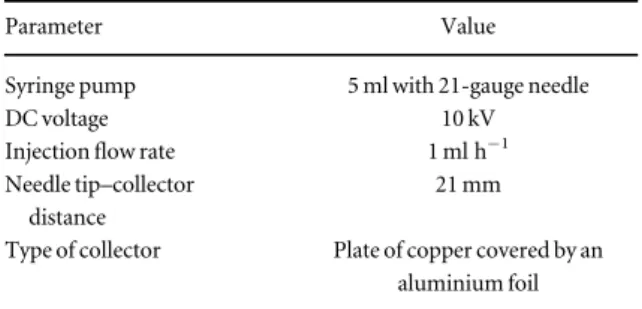
2.1. Substrate production and characterization The scaffolds, on the top of which conductive patterns were printed, are composed of carbonfibres derived from the precursor PAN. CNTs were also embedded in the electrospinning solution, and two substrates, later referred to as PAN and PAN+CNT, were produced in order to investigate the effects of includ-ing nano-conductive particles on thefinal product of polymerization. PAN and PAN+CNT substrates were obtained by electrospinning of a solution of 8 wt% PAN(150 000 g mol−1) dissolved in dimethyl-formamide(DMF). The solution was stirred for 48 h at 30°C. The PAN+CNT solution was made by dissol-ving 1 wt% CNTs in DMF(by sonication for 1 h at 35°C) and adding PAN in a second step. Subsequently, both materials were electrospun using a 5 ml syringe with a 21-gauge needle on aflat collector composed of one plate of copper, covered by an aluminium foil. Afterwards, the fibres were subjected to thermal stabilization at 280°C for 6 h and to pyrolysis up to 1050°C in a controlled atmosphere (table1,figure1)
[63]. The final fibrous mats were dark coloured, brittle,
thinfilms.
2.1.1. Morphological characterization
Characterization of the fibres was performed using a scanning electron microscope(SEM) under ambient conditions (23 °C, 50% relative humidity) and 20.00 kV vacuum. Measurements of the average diameter of thefibres were calculated using ImageJ software. For both the PAN and PAN+CNT sam-ples, 120 measurements in different and random spatial regions were taken.
The electron diffraction pattern was analysed using a transmission electron microscope(TEM) to
Table 1. Parameters for the electrospinning process.
Parameter Value
Syringe pump 5 ml with 21-gauge needle
DC voltage 10 kV
Injectionflow rate 1 ml h−1 Needle tip–collector
distance
21 mm
Type of collector Plate of copper covered by an aluminium foil
detect the degree of graphitization in the nanofibres. In addition, the average crystallite thickness(Lc) was
measured from the distance between the layers by the fringes.
The material thickness was measured using a Schut micrometer(accuracy ±2 μm) under ambient conditions.
2.1.2. Electrical properties
A four-point measurement was used to detect the sheet resistance of the materials in clean-room condi-tions (Veeco Instruments Inc., Four Point Probe, model FPP-100). For each material, 15 repetitions on two different samples were recorded.
2.2. Ink
In this study, a commercial AgNP solution ink SI-AJ 20X(supplied by AGFA) was used. Table2reports the main properties of the ink. The interaction forces between ink particles and substrates (PAN, PAN+CNT and glass) were studied using a sessile drop on a Contact Angle System OCA 15plus for wettability tests under ambient conditions. This is a common test in printing techniques to check the substrate–ink interaction and the adhesion to a part-icular substrate. A sessile drop of 2μl was deposited on the substrates via a Nordson 7018339 straight, 25-gauge, 1.5 inch long red dispensing needle. Measure-ments were recorded automatically andfitted by the
software from the starting point when the drop was deposited on the substrate until the measurement was stable(∼5 s).
2.3. Printing process 2.3.1. Nebula 5X-100 s
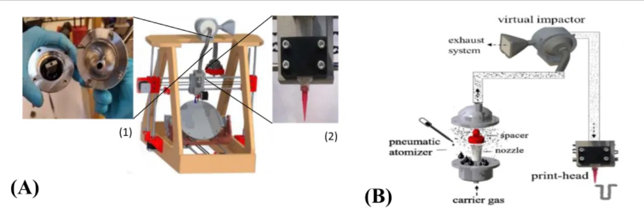
The printing process was conducted on a Nebula 5X-100 s, a five-axis home-made nebulized jet-based printer, designed and manufactured at the Advanced Manufacturing Laboratory(AML), Campus De Nayer, KU Leuven, Belgium(figure2(A)). The machine offers
a printing speed in the range of 0–200 mm min−1, a
stand-off distance of 1–5 mm and a positional accur-acy of±10 μm on the z-axis and ±20 μm on the x and y axes. Typically, conical-shaped nozzles are mounted on the deposition head to ensure jet focusing. In this study, 10 cm3 Nordson EFD Luer lock nozzles (Ø = 250 μm and Ø = 610 μm, length 31.6 mm) are employed. The Nebula 5X-100 s is equipped with a pneumatic atomizer for the creation of an aerosolflow at controlled air pressure in the range of 0–5 bar. The aerosolflow subsequently goes in a virtual impactor, which is used to filter the accelerating gas to get a focused beam. A schematic view of the printing process is given infigure2(B). For a reliable process,
the minimum ink level required in the atomizer is ∼3 ml and the printed line resolution is in the range of 100–300 μm, depending on the particular ink–sub-strate combination. The printer has been validated on various flat and curved substrates using different silver inks.
2.3.2. Experimental printing methodology
Various experimental methodologies were used to identify suitable printing parameters for specific ink– substrate combinations. Experiments werefirst con-ducted on glass substrates(from VWR) as a positive control, and then transferred to PAN mats. The glass experiments consisted of afirst screening session, of type 2k(k>0) full factorial design (two levels, k=4 factors, five repetitions), followed by a greedy algo-rithm investigation within an adapted process win-dow. The following factors were investigated in the screening session: nozzle diameter Ø(μm), stand-off distance z(mm), control pressure p (bar), print speed s (mm min−1) and number of printed layers n as shown
in table3.
Based on the results obtained, z and p were further investigated in a greedy algorithm investigation. Accordingly, an additional greedy algorithm invest-igation was conducted on the PAN substrates to fine-tune the best practice combination obtained on glass. Due to the higher wettability (see section 3.2 and figure7) and the fragility of PAN and PAN+CNTs,
40 layers were printed instead of 10 and p was kept low. Finally, a validation test composed offive repetitions was executed for each best practice parameter combi-nation identified on glass and carbon-fibre-based
Figure 1. The(pre)-carbonization phase in the pyrolysis process: afirst pre-carbonization phase from room temper-ature at 20°C, with an increase of 4 °C min−1for 1 h, followed by another hour at 300°C. Subsequently, a second increase of 2.5°C min−1for 5 h, followed by the carboniza-tion phase at 1050°C for 1 h. Finally, a cooling process from 1050°C to 20 °C over a period of 3 h.
Table 2. Properties of the SI-AJ 20X ink. For more details see the ink datasheet[64].
Feature Description
Printing process Optimized for aerosol jet®printing Functional material 19.0 wt% silver Viscosity 7.1 mPa s Ave. particle size 100 nm Appearance Dark-grey colour
substrates. The samples were in the form of printed lines 10 mm long. After printing, thermal curing(180° for 1 h in a Heraeus oven) was applied in order to reach the desired conductivity, due to evaporation of the ink solvent and sintering of the AgNPs. Table3lists the experimental conditions selected for each test campaign.
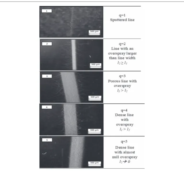
The quality of the printed line, q, was chosen as the response of interest. In PE, a well-defined track is required to ensure proper electrical transmission, more specifically depending on line density, straightness of
the edge line and the amount of overspray(OS). The OS is here defined as the scattered material deposited, in the form of drops or streams, next to the line edges. For quantification purposes, we chose as the explicit value of the OS(l2), the difference between the line width (l)
and the line width including the OS(l1) (figure3).
Char-acterization was conducted by optical microscopy (Hirox KH−8700). The printed lines were finally ranked from 1 (worst) to 5 (ideal), according to the guidelines given infigure4, and the parameter combi-nations leading to q 4 were further validated and
Figure 2. Nebula 5X-100 s printer(A) and schematic overview of the printing process (B): machine and tools, details of the atomizer (1) and the print head (2). The aerosolized particles flow through the printing process using a pneumatic atomizer.
Figure 3. Phenomenon of overspray in a printed line: l2=l−l1.
Table 3. Parameter setting for investigation of the printing process on glass, PAN and PAN+CNT substrates under ambient conditions(23 °C, 50% relative humidity) .
Parameter
Full factorial design
screening 2k(k>0) Greedy algorithm investigation
Glass substrate Glass substrate PAN, PAN+CNT substrates
Nozzle diameter, Ø(μm) 250 610 250 610 250 610
Stand-off distance, z(mm) 0.7–2 0.8–2.5 1z5a 0.5z2a 1z3a 1.5–1.75 Control pressure, p(bar) 1–2.5 1–2.5 1p2a 1p1.75a 1.25p2a 1.25–1.50
Printing speed, s(mm min−1) 50–150 50–150 50 50s150 30–50–100 50
No. of layers 5–10 5–10 10 10 40 40
Ink SI-AJ20X
repeated(five times). The electrical resistance R (Ω) of the best printed samples was also recorded, using a two-point probe method with a Digital Voltmeter 3456 A (HP) on a printed pattern of 10 mm×0.3 mm. 2.4. Biocompatibility and cellular adhesion
In the following paragraphs, cell viability assays on humanfibroblasts (HFs) and human-induced pluri-potent stem cell (iPSC)-derived neural stem cells (NSCs) at different time points are described.
2.4.1. Cell viability assay on HFs up to 48 h
Cell culture tests were performed to evaluate the effects of the AgNP(Øavg,particle size∼100 nm) ink SI-AJ20X
ink, PAN+CNT mats and printed silver on the fibrous network (PAN+CNTs + Ag) on cellular viability and proliferation. In particular, biocompat-ibility wasfirst verified on HFs (BJ cell line ATCC® CRL-2522™) at a single time point of 48 h.
SI-AJ20X ink. Three samples of silver SI-AJ20X ink (pure ink, not aerosolized) were painted on glass cov-erslips and subjected to post-processing thermal cur-ing (180° for 1 h in a Heraeus oven). Before cell seeding (24-well plate) all the samples were washed
with three times with phosphate-buffered saline(PBS) and sterilized in an autoclave.
PAN+CNTs. Three rectangular samples of PAN+CNTs (5 mm×10 mm) were washed with PBS for 3 h and sterilized in an autoclave. Subse-quently, all samples were placed directly into a 48-well plate.
PAN+CNTs + Ag. Six rectangular samples of PAN+CNTs (5 mm×5 mm) with 10 printed silver lines were analysed at each point. The printing para-meters were as in table5 for PAN+CNT samples
(Ønozzle=610 μm, s=50 mm min−1, z=1.5 mm,
p=1.25 bar). Specifically, three samples were printed at n=40 layers and three at n=1 layer to highlight the effect of the quantity of printed silver
(Øavg,particle size∼100 nm) on cell viability, as
men-tioned in the literature[51,54–61]. The samples were
subjected to the same post-sintering process as for SI-AJ20X ink(180° for 1 h in a Heraeus oven), although a different ink–substrate wettability has to be con-sidered. All samples were washed with PBS for 3 h and sterilized in an autoclave before cell culture. Subse-quently, all samples were placed directly into a 48-well plate.
Cell viability assay. HFs were cultured in Dulbec-co’s modified Eagle’s medium (DMEM) with 10% fetal bovine serum, 1% L-glutamine and 1% peni-cillin/streptomycin (all Euroclone). Cells were main-tained at 37°C in a saturated humidity atmosphere containing 5% CO2. A concentrated cell suspension of
2× 10⁵cells cm−2was deposited onto each support and incubated for 30 min before the plate wasfilled with a suitable volume of DMEM. The biocompat-ibility was estimated after 48 h by measurement of ATP, using the CellTiter-Glo 3D Cell Viability Assay (Promega cat. no. G9681). This assay is a homo-geneous method to detect the number of viable cells based on quantification of ATP, which is a marker for the presence of metabolically active cells. Cells were lysed directly on the substrates according to the manu-facturer’s instructions. An ATP standard curve (range of 10μM to 10 nM) was generated using the ATP dis-odium salt(Promega cat. no. P1132) in order to com-pare luminescence of samples with luminescence of a standard determining the ATP concentration detec-ted. Luminescence was measured using a Tecan Infinite®M200 multi-functional microplate reader. 2.4.2. Cell viability assay for HFs and human-iPSC-derived NSCs up to 96 h
According to the results of thefirst study on HFs at 48 h (see section 3.5), further ATP studies were
performed with HFs and human-iPSC-derived NSCs on the final product on 24-well plates. The final product is PAN+CNT substrates with 10 printed silver lines at n=40 layers and the relative printing parameters reported in table 5 (Ønozzle=610 μm,
s=50 mm min−1, z=1.5 mm, p=1.25 bar),
subse-quently sintered at 180° for 1 h in a Heraeus oven. All samples were washed with PBS for 3 h and sterilized in an autoclave before the cells were cultured. Biocom-patibility was estimated after 24, 48 and 96 h(three samples for each point), by measurement of ATP using the same CellTiter-Glo 3D Cell Viability Assay (Pro-mega cat. no. G9681) as described in the previous subsection.
A parallel experiment on ATP measurement with the same Promega assay kit was performed on human-iPSC-derived NSCs and thefinal product after 24, 48 and 96 h(two samples for each point). Human-iPSC lines reprogrammed and characterized in our labora-tory were differentiated into NSCs, using the protocol reported by Ferraro et al[65]. Specifically, a Matrigel
coating was applied to the substrates for 1 h at 37°C before cell seeding. A concentrated cell suspension (2×10⁵
cells cm−2) was deposited onto each sample and incubated for 20 min beforefilling with an appro-priate volume of Neural Expansion Medium.
2.4.3. Immunofluorescence assay
In addition to the quantitative analyses, immuno fluor-escence assays were performed to observe the cellular
morphology (nuclei and cytoskeleton). Based on previous results, tests were implemented on AgNP
(Øavg,particle size∼100 nm) SI-AJ20X ink and
PAN+CNT substrates up to 5 days. 2.4.4. Silver SI-AJ20X ink
Immunofluorescence was performed to study the effects of silver SI-AJ20X ink on glass with respect to cellular adhesion and morphology. Specifically, three samples of silver SI-AJ20X ink were painted on glass coverslips and subjected to post-processing thermal curing(180 °C for 1 h in a Heraeus oven) to evaporate the solvent. All the specimens were washed with PBS three times and sterilized in an autoclave before cell seeding. A concentrated HF cell suspension(BJ cell line ATCC®CRL-2522™) at 5×10⁴ cells cm–2was deposited onto each support and incubated for 30 min before filling the plate with a suitable volume of DMEM. After 5 days in culture, cells werefixed using the Fix&Perm Sample Kit®(SIC) for 30 min (15 min fixation and 15 min permeabilization), incubated with blocking solution(iBindTM 5X Buffer, Invitrogen) for 45 min, and stained with Phalloidin(Sigma Aldrich), which marks the cytoskeletal components of cells. Cell nuclei were then counterstained with Hoechst 33342 for 5 min to highlight the cellular nuclei of living cells. The samples were mounted onto glass slides and observed under an invertedfluorescence microscope (Olympus IX70 inverted microscope); the images were analysed with Image-Pro Plus software v.7.0(Media Cybernetics).
2.4.5. Adhesion of NSCs on the carbonized substrates Human-iPSC-derived NSCs [65, 66] were used to
perform cell compatibility tests on three samples of PAN+CNT carbonized fibres. The substrates were positioned in a 24-well plate then washed with PBS and sterilized in an autoclave. A Matrigel (Thermo-Fisher Scientific) coating was applied for 1 h at 37 °C. NSCs were passed through a 100μm strainer (Fisher Scientific) to obtain a single cell suspension and plated at 5×10⁴
cells cm−2. A concentrated cell suspension was deposited on the samples and incubated for 20 min before filling the 24-well plate with the appropriate volume of StemPro NSC SFM (Thermo-Fisher Scientific). Cells were maintained at 37 °C in an atmosphere containing 5% CO2. After 5 days in
culture, the cells werefixed and permeabilized using Fix&Perm-Reagent kit(SIC), blocked for 45 min with iBindTM Buffer solution(Invitrogen) and stained with Phalloidin, specific for the cytoskeletal component of the cells. Cell nuclei were counterstained with Hoechst 33342 to show the living cells. Samples were observed with an inverted fluorescence microscope (Olym-pus IX70).
3. Results and discussion
3.1. Substrate characterization
Morphological characterization of PAN and PAN+CNTs (diameter of fibres, density of the fibrous networks, orientation of fibres and presence of beads in the pattern) was carried out. Figure5shows SEM images for both PAN and PAN+CNTs at two levels of magnification. Both the substrates present an homogeneous distribution of randomly oriented fibres.
PAN samples have a higher density offibres than PAN+CNTs. PAN fibres seem more tangled and with a higher concentration of round beads. The for-mation of some beads might be related to poor disper-sion of the nanoparticles and incomplete solvent evaporation: this suggests that, although CNTs seemed to be well dispersed by sonication in DMF, some of the long nanotubes were entangled with each other. Further electrospinning parameter optim-ization will be performed to avoid these defects. The average thickness of the PAN+CNT material is 190μm (σ2=0.02), compared with the 310 μm (σ2=0.06) for PAN. The TEM images exhibit the
differences in the fibre surfaces (figure 6): the
PAN+CNT fibres have a multi-layered wall of CNTs in the shell region(figure6(a)). A distinction between
core and shell regions is detected close to thefibre sur-face. Here it is possible to distinguish the orientation of the fringe in the shell region, which indicates good alignment of the CNTs along thefibre axis. A higher
grade of graphitization in PAN+CNT than in PAN fibres is also detected (figure6(b)): the electron
diffrac-tion pattern shows concentric circles formed from multiple sets of six-fold symmetrical spots, which are an index of the grade of graphitization in thefibrous network. This derives from the multi-layered distribu-tion of sp2hybridized carbon planes(from CNTs and/
or grown carbon crystals) which are randomly orien-ted with respect to the incident electron beam.
Measurement of the resistivityρ shows that PAN and PAN+CNTs are slightly conductive in the same range of∼2 Ω cm. This result can be interpreted from a morphological point of view: even if the embedded CNTs have increased the conductivity of thefibres, their less ordered orientation decreased the propaga-tion of electrical current in the matrix. Table4reports a summary of the material properties which have been characterized.
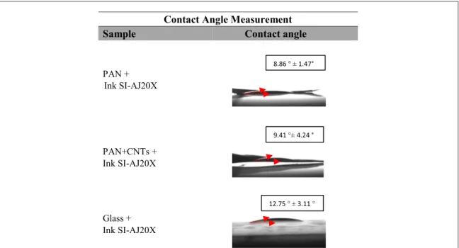
3.2. Ink–substrate interaction
High wettability of silver ink is revealed for all the samples, showing good interaction between the ink and the substrates. This phenomenon usually favours a high quality of printed lines for a given best practice printing approach. Figure7reports the contact angle measurements on each substrate. Specifically, both PAN and PAN+CNTs reveal the highest wettability, most likely due to their mat structure, and conse-quently higher absorption.
Figure 5. Morphological characterization of the substrate: SEM images of PAN(5000×) (a), 10 000× (c) and SEM images of PAN+CNTs at magnification 5000× (b) and 10 00o× (d). Electron high tension (EHT) = 20 000 kV.
3.3. Printing experiment 3.3.1. Glass substrate and silver ink
Figure8shows the analyses of the results obtained on glass for a full factorial screening design on both nozzles.
With the use of a 250μm nozzle (figure8, Pareto Chart), the most significant parameters are, in order: the printing speed, s, the interaction between the con-trol pressure and printing speed, ps, and the number of layers, n. In addition, the main effect plot shows a small increase in line quality when s assumes low values and the number of deposited layers, n, increa-ses, this latter being directly proportional to the line density. Instead, the pressure, p, is revealed to be the most significant parameter when using a 610 μm noz-zle. The effect of pressure is also opposite when com-paring the results obtained with the two nozzle diameters. This effect can be explained by referring to Bernoulli’s principle, according to which the kine-matic status of afluid is inversely proportional to the cross-sectional area of the vessel through which the fluid is flowing.
On average, the results are assessed as being of quality 2, with small variations with changes of the input parameters (figure 8, Main Effects). The
regression analyses for a 250μm and a 610 μm nozzle give, respectively, R2250μm32.10% and R2610μm26.21%,
hence indicating that, in the selected window, the investigated parameters are only partially responsible for the results obtained.
Accordingly, a greedy algorithm was performed in an adapted process window for further parameter investigation. The experimental campaign was speci fi-cally applied on p and z(off-set distance, introduced based on the previous experience acquired), by gradu-ally increasing the parameter values, one by one, and by performing the printable combinations only. The p values were intentionally kept on the lower side to ensure more robust results. Figure9shows the con-tour plot for the line quality with variation of off-set and pressure. The graph is the result of experimental data obtained for given combinations of p and z and interpolated data when not present.
Non-linear behaviours could also be detected, as intervals of four or more levels were investigated. The quality results are promising(up to level four), but they are stillfluctuating without revealing a particular trend. The contour plot does not reveal the presence of a global optimum, but only local best parameter combinations.
Figure 6. Influence of CNTs embedded in PAN samples. The TEM images show the micro-structure of PAN+CNT fibres, with a distinction between core(C1) and shell (C2) regions (A). Grade of graphitization (B) of CNTs embedded in PAN, with respect to the
PANfibres (C).
Table 4. Material characterization. The table reports the values of morphological and electrical characterizations, respectively, for PAN and PAN+CNT materials.
Material property Mean(μ) or standard deviation (σ2) PAN PAN+CNT
Fibre diameter, d(μm) μ 0.29 0.27 σ2 0.05 0.05 Substrate thickness, t(mm) μ 0.31 0.19 σ2 0.06 0.02 Sheet resistance,σ (Ω ◻−1orΩ) μ 67.1 102.6 σ2 9.5 21.3 Resistivity,ρ ( Ω cm) μ 2.1 1.9 Crystallite thickness, L(nm) μ — 15.1 σ2 — 4.9
In general, q 4 can only be obtained at low p and z; instead, if z is higher than 0.75 mm, the desired qual-ity q 4 can be achieved with increasing p for a 250μm nozzle. For this reason, the best practice is cho-sen as: s=50 mm min−1, z=3.5 mm, p=1.75 bar
and n=10 layers. Instead, a q 4 can be achieved with low s and p and high z, or vice versa, for a 610μm nozzle. For this reason, the best practice is: s= 50 mm min−1, z=1.75 mm, p=1.25 bar and n= 10 layers. Those combinations of parameters will
Figure 8. Analysis of the experimental design on a glass substrate: full factorial screening on a 250μm and a 610 μm nozzle, respectively.
eventually be repeated and further validated, as repor-ted in section3.4.
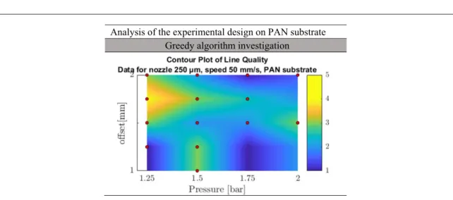
3.3.2. PAN, PAN+CNT substrates and silver ink According to the analysis developed on glass substrate, a similar greedy algorithm investigation was applied to PAN and PAN+CNT substrates. The experimental analysis started with a 250μm nozzle and focused on p and z, by gradually increasing the parameter values of 0.25, one by one, and performing printable combina-tions only. Figure10shows the contour plot for the line quality obtained for given combinations of p and z, with the use of a 250μm nozzle on PAN substrate. As for glass substrate, interpolation of the exper-imental data shows non-linear behaviour. The same range of quality line(up to level four) is detected with local best parameter combinations but without a specific trend. In general, q 4 can only be obtained at low p and z; for this reason, the best practice is chosen as: s=50 mm min−1, z=1.75 mm, p=1.25
bar and n=40 layers. A more restricted parameter window was studied for a 610 μm nozzle. The experiments were based on the previous results on PAN and PAN+CNT substrates using a 250 μm
nozzle and on the analyses performed on glass substrate using a 610μm nozzle. With this knowledge, q 4 is detected to be obtained again at low p and z; the best practice is chosen as : s=50 mm min−1, z=1.5 mm, p=1.25 bar and n=40 layers.
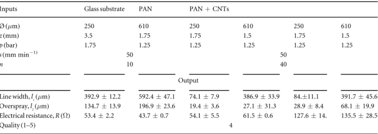
3.4. Validation test and best printing practices Table 5 reports the best printing combinations obtained for glass, PAN and PAN+CNT substrates, respectively. Five repetitions for each combination of parameters were conducted to validate the results. The results were characterized with regard to line width, OS and achieved electrical resistance. The quality of the results was also cross-checked and confirmed to have a value of at least 4, as in previous experiments. No difference was detected in the best practice values for both the nozzles on PAN and PAN+CNT substrates because the twofibrous networks can be considered as a similar substrate from the point of view of the printing process. Specifically, a comparison between the carbon-fibre substrates and the glass substrate reveals that, for a 250μm nozzle, a lower pressure is required, which needs consequently a lower
Figure 9. Analysis of the experimental design on a glass substrate: greedy algorithm investigation on a 250μm and a 610 μm nozzle, respectively. Line quality goes from 1(blue) to 5 (yellow).
stand-off distance(according to the Bernoulli princi-ple). This is because of the high fragility of the substrates. On the other hand, the use of a 610μm nozzle requires for each substrate a low pressure equal to p=1.25 bar. In this case, instead, the main difference between glass and carbon-fibre-based sub-strates is found in the off-set z: a lower z is set for PAN and PAN+CNT substrates, due to the absorption of aerosolized micro-droplets inside thefibrous mats. As a consequence, a higher number of printed layers (n=40), than that on glass (n=10), is also required. This condition also explains the smaller values of line width and OS with respect to the results obtained on glass.
The overall analysis demonstrates the feasibility of printing conductive lines on electrospunfibrous pat-terns. The values of electrical resistance on glass and PAN substrates are approximately in the range of 50Ω, which is in line with the PE requirements. Instead, PAN+CNT substrates exhibit higher electrical resistance, due to the higher sheet resistance (see table4), which induces more significant signal
disper-sion. Hence, the morphology and conductivity of the substrate influence the creation of efficient bio-electrical systems. In addition, the results regarding line width values are in line with their respective
Ønozzlesize, even if parameter optimization based on
the relative stand-off distance can be performed. Spe-cifically, although the micro-scale resolution of the line width in terms of system performance cannot reach that of industrial nebulized jet-based printers, such as the Aerosol Jet®printers by Optomec(down to 10 μm) [39] or Nanojet™ (NJ) printers by IDS
(down to 15 μm) [67], it is comparable from the point
of view of cost-effectiveness. This can open up possibi-lities in a low-cost market scenario.
3.5. Biocompatibility and cellular adhesion
Figure11reports ATP assay results(time point 48 h) of HFs cultured on SI-20X ink droplets, PAN+CNT samples and their combination, respectively. The relative values of %ATP concentration of samples,
with respect to the corresponding control sample, are shown in the graph, while ATP(μM) concentrations are reported in the table. As a first observation, PAN+CNT mats reveals the highest biocompatibil-ity, while PAN+CNTs + Ag at n=40 layers has the lowest value. PAN+CNTs + Ag at n=1 layer and silver ink painted on glass coverslips have intermediate values.
Specifically, despite the presence of CNTs in the fibrous network, PAN+CNT substrates are suffi-ciently biocompatible with respect to the control sam-ple. Besides, the existence of‘beads’ in the electrospun fibres, produced by incomplete evaporation of the sol-vent in the solution, does not seem to have a consider-able influence on cell viability and proliferation.
The results on PAN+ CNT +Ag samples, with regard to the variation of AgNP suspensions, also reveal the toxicity of silver ink and its dose-dependent nature. This is in accordance with the complex relative nature of the biological activity of AgNP powders, in a multi-factorial dose-, agglomera-tion- and dissolution rate-dependent environment. In addition, PAN+CNT + Ag samples at n=40 layers show lower %ATP concentrations than silver ink dro-plets on glass coverslips. This may be explained by spe-cific surface–cell interactions, caused by the different deposition processes: nebulized jet-based printing and painting, respectively. We observed in our experi-ments that printed lines delaminate more easily on glass that on the carbon-fibre substrates. Hence, we assume that the nebulized jet-based printing process can cause different AgNP particle agglomerations, resulting in distinctive Ag+ion release and cell interac-tion. This effect will be analysed in future studies.
Figure12shows ATP(μM) concentrations (time points 24, 48 and 96 h) of HFs and human-iPSC-derived NSCs, cultured on PAN+CNT with printed Ag substrates(10 lines at n=40 layers). Specifically, HFs proliferation follows a positive growth trend on thefinal product for the first time points, and a nega-tive one visible at 96 h(figure12(A)).
The intrinsic variability of the nebulized jet-based process in terms of the quantity of silver deposited on
Table 5. Best practice printing parameters for glass, PAN and PAN+CNT substrates using silver ink SI-AJ20X, with the respective results (margin of error with confidence level of 95%).
Inputs Glass substrate PAN PAN+CNTs
Ø(μm) 250 610 250 610 250 610 z(mm) 3.5 1.75 1.75 1.5 1.75 1.5 p(bar) 1.75 1.25 1.25 1.25 1.25 1.25 s(mm min−1) 50 50 n 10 40 Output Line width, l1(μm) 392.9±12.2 592.4±47.1 74.1±7.9 386.9±33.9 84.±11.1 391.7±45.6 Overspray, l2(μm) 134.7±13.9 196.9±23.6 19.4±3.6 27.1±31.3 28.9±8.4 68.1±19.9 Electrical resistance, R(Ω) 53.4±2.2 43.7±0.7 54.1±5.5 61.5±0.6 127.6±14. 135.5±28.5 Quality(1–5) 4
the substrate (as previous data confirmed) has an influence on the toxicity of the different samples. However, proliferation of human-iPSC-derived NSCs follows a negative trend by 48 h(figure12(B)),
reach-ing values approximately equal to zero. In this context, it must be noted that the cells used are not primary neurons. These results demonstrate the unfeasibility of direct contact between commercial AgNP
(Øavg,particle size∼100 nm) ink commonly used in PE
and neural cells.
3.5.1. Immunofluorescence assay
Figure 13 reports immunofluorescence microscopy images of HFs on a drop of SI-AJ20X silver ink and iPSC-derived NSCs on PAN+CNT carbonized fibres in different regions of the substrate, after 5 days. Specifically, the sintered droplets of silver ink can tolerably sustain cell adhesion and survival, even if HFs seem to suffer, as confirmed by the staining of nuclei and the cytoskeleton(figure13, top row). On the other hand, immunofluorescence images of adhe-sion of iPSC-derived NSCs on PAN+CNTs (figure13, bottom row) show that cells spread on the
available surface, confirming the recognition of the substrate. Human-iPSC-derived NSCs colonize the fibrous network as the cytoskeletal protrusions are interconnected through the carbonfibres. These promising results lead to the possibility of differentiat-ing the stem cells into neurons on the pyrolysed scaffolds to enhance the maturation of adult cells by the application of morphological, mechanical and electrical stimuli.
4. Application and future activities
A designed RC (resistance—capacitor) circuit for standard printed electronics application, such as LEDs, was printed on glass and PAN+CNT sub-strates to test the feasibility of printing functional conductive patterns and circuits, as shown infigure14. On a glass substrate, an electrical resistance of∼130 Ω was measured across the rectangular pads(connecting printed line width l1=606.8±33.1 μm, rectangular
area∼3.4 mm2), indicated as 1 and 2 in figure14(a).
On the same path, values of∼480 Ω were instead
Figure 11. %ATP relative concentration of HFs cultured on PAN+CNT substrates with different numbers of printed silver substrates on a 48-well plate(as control) and on SI-AJ20X ink sintered droplets on coverslips on a 24-well plate (as control), evaluated at a time point of 48 h.
measured on PAN+CNTs (figures 14(b) and (d)),
validating the functionality of the printed circuit also for high sheet resistance bio-conductive mat pads (connecting printed line width l1=424.4±55.3 μm,
rectangular area∼3.6 mm2).
These results represent a starting point for future investigations on ES across scaffolds in culture med-ium, such as the design of circuits with rectangular
biphasic pulse generators and no residual charges [18,68]. By means of a DC power supply, for instance,
ES can be achieved through establishment of an elec-trical field, uniformly distributed on the external membrane of the cells[69] and with specific voltages
in the range of 4.5–450 mV mm−1.
Several methods have already been investigated in the literature in order to overcome the toxicity of
Figure 12. ATP concentrations(μM) of HFs (A) and human-iPSC-derived NSCs (B) cultured on PAN+CNT with printed Ag substrates(10 lines, n=40 layers) and on a 48-well plate (as control), estimated at different time points (24 h, 48 h, and 96 h).
AgNP solutions, for example surface coating[70,71]
and silver encapsulation via a printed passivation layer. Specifically, several chemicals can be applied as surface coating agents to avoid direct interaction with the biological system, preventing the oxidation of Ag+ ions. Citrate and polyvinylpyrrolidone can be used as surface coating agents for AgNPs[51], but also PDMS,
polyimide[23] or parylene-C [71,72], as passivation
and insulating(printed) layers. Therefore, considering that direct contact between the biological system and
AgNP inks designed for printing of electronics is not possible, due to high levels of toxicity, potential encap-sulation via a surface coating or a printed layer will be surely investigated in future studies.
5. Conclusion
An ideal neural scaffold will usually have multiple cues for axon guidance; these could be obtained by
Figure 13. Top row:fluorescence microscopy images of HFs after 5 days on a drop of SI-AJ20X silver ink (Phalloidin, staining the cytoskeleton, in green, nuclei in blue), with detailed images of the nuclei in proximity of the edge of the drop (A), and of the Phalloidin, respectively on the drop(B) and at the edge of the drop (C). Bottom row: fluorescence microscopy images of iPSC-derived NSCs on PAN+CNT carbonized fibres in different regions of the substrate after 5 days. The regions were randomly selected to verify the homogeneity of cells spreading on the surface.
Figure 14. Printing of a RC circuit on glass and PAN+CNT substrates. Printing parameters on glass (a), (c): nozzle 250 μm (s=50 mm min−1, z=3.5 mm, p=1.75 bar, n=10 layers for conductive tracks and n=3 layers for components); nozzle 610
μm (s=150 mm min−1, z=0.8 mm, p=1.5 bar, n=3 layers for battery placement). Printing parameters on PAN+CNTs (b),
(d): nozzle 250 μm (s=50 mm min−1, z=3.5 mm, p=1.75 bar, n=25 layers for conductive tracks, 21 for components and
introducing conductive electrodes[2,4]. The present
study investigates the feasibility of using printing of electronics for bio-electrical neural tissue engineering applications by means of a nebulized jet-based print-ing process. More specifically, the study has con-cerned:(i) production of biocompatible electrospun-pyrolysed fibrous mats via the electrospinning of neural cell cultures (PAN, mean fibre diameter d=0.29 μm, sheet resistance ρμ=67.1 Ω ◻−1), with
the addition of embedded CNTs (PAN+CNTs, mean fibre diameter d=0.27 μm, sheet resistance ρμ=102.6 Ω ◻−1); (ii) identification of the most
suitable combination of parameters for printing con-ductive lines on these substrates;(iii) toxicity tests of the selected substrates and ink; and(iv) printing of a functional circuit for concept validation.
The results showed high wettability for ink –sub-strate adhesion, allowing the possibility of printing well-defined and functional patterns, without delami-nation/desquamation in physiological solutions, and with electrical resistances in the range of 50Ω for both glass and PAN substrates, and in the range of 130Ω for PAN+CNT substrates for a best practice combination of print parameters and sintering processes.
However, the cytotoxic effects of the most common ink used in PE, such as AgNP(Øavg,particle size∼100 nm)
solutions, on HFs and human-iPSC-derived NSCs via ATP assay for three-dimensional cell cultures, suggest the need to implement surface coating or encapsulation of the circuit in order to increase cell viability. Future studies will focus on this. On the other hand, the work demonstrates the technological potential of applying PE techniques to produce innovative bio-electrical scaf-folds for drug discovery or neural ES for in vitro models, with enhancements of connection efficiency among cells and substrates. In fact, the main advantage of the nebulized jet-based printing technique is its versatility: both planar and free-formed substrates,flexible or rigid supports, textile and paper, can be investigated, even if its application to biomaterials or biomimetic tissues is still unusual. Based on the literature evidence, examples in thefield of tissue engineering [37,71] have already
been demonstrated. Furthermore, the possibility of printing with a broad selection of inks, which can bal-ance biocompatibility and electrical conductivity(such as PEDOT:PSS, collagen, carbon-based inks, etc), can completely avoid the problems concerning potential cytotoxic effects.
Future work will involve optimization of electro-spinning parameters and the investigation of printing with biocompatible inks for the design and validation of conductive PE on tissues for neuronal stimulation and related differentiation, but also axon guidance and neurite outgrowth studies. Eventually, further study on the potential production of three-dimensional conductive scaffolds, already on-going on nanofibres [3,18], will be implemented using nozzle-based
print-ing techniques[33] in a
multi-material/multi-func-tional vision.
Acknowledgments
We would like to express our gratitude to Dr Fernando Cortes for providing silver ink from Agfa(Belgium) and U Hasselt for giving us the possibility to perform wettability measurements. We also thank the AML Lab for technical support and critical discussions during the experiments, in particular Akash Verma and Jie Zhang. Finally, we would like to thank Mohit Sharma(ESAT, KU Leuven) for fruitful discussions regarding data analyses, and Patrick Pelgrims and Yurre De Weerdt(Thomas More, Belgium) for providing the electrical design circuit.
ORCID iDs
Miriam Seiti
https://orcid.org/0000-0002-9619-3788
References
[1] Hewes L 2018 World Alzheimer report 2018 Prof. Geogr.2 14–20
[2] Li G N and Hoffman-Kim D 2008 Tissue-engineered platforms of axon guidance Tissue Eng. B14 33–51
[3] McMurtrey R J 2014 Patterned and functionalized nanofiber scaffolds in three-dimensional hydrogel constructs enhance neurite outgrowth and directional control J. Neural Eng.11 066009
[4] Subramanian A, Krishnan U M and Sethuraman S 2009 Development of biomaterial scaffold for nerve tissue engineering: biomaterial mediated neural regeneration J. Biomed. Sci.16 108
[5] Boni R, Ali A, Shavandi A and Clarkson A N 2018 Current and novel polymeric biomaterials for neural tissue engineering J. Biomed. Sci.25 90
[6] Lee J Y, Bashur C A, Goldstein A S and Schmidt C E 2009 Polypyrrole-coated electrospun PLGA nanofibers for neural tissue applications Biomaterials30 4325–35
[7] Sill T J and von Recum H A 2008 Electrospinning: applications in drug delivery and tissue engineering Biomaterials29 1989–2006
[8] Stepanyan R et al 2016 Nanofiber diameter in electrospinning of polymer solutions: Model and experiment Polymer97 428–39
[9] Kumbar S G, James R, Nukavarapu S P and Laurencin C T 2008 Electrospun nanofiber scaffolds: engineering soft tissues Biomed. Mater.3 034002
[10] Xie J, MacEwan M R, Schwartz A G and Xia Y 2010
Electrospun nanofibers for neural tissue engineering Nanoscale
2 35–44
[11] Yang F, Murugan R, Wang S and Ramakrishna S 2005 Electrospinning of nano/micro scale poly(L-lactic acid) alignedfibers and their potential in neural tissue engineering Biomaterials26 2603–10
[12] Tang M, Song Q, Li N, Jiang Z, Huang R and Cheng G 2013 Enhancement of electrical signaling in neural networks on graphenefilms Biomaterials34 6402–11
[13] Li N et al 2013 Three-dimensional graphene foam as a biocompatible and conductive scaffold for neural stem cells Sci. Rep.3 1–6
[14] Guo W et al 2016 Self-powered electrical stimulation for enhancing neural differentiation of mesenchymal stem cells on graphene-poly(3,4-ethylenedioxythiophene) hybrid microfibers ACS Nano10 5086–95
[15] Lovat V et al 2005 Carbon nanotube substrates boost neuronal electrical signaling Nano Lett.5 1107–10
[16] Huang Y J, Wu H C, Tai N H and Wang T W 2012 Carbon nanotube rope with electrical stimulation promotes the
differentiation and maturity of neural stem cells Small8 2869–77
[17] Cellot G et al 2011 Carbon nanotube scaffolds tune synaptic strength in cultured neural circuits: novel frontiers in nanomaterial–tissue interactions J. Neurosci.31 12945–53
[18] Lee S J et al 2018 3D printing nano conductive multi-walled carbon nanotube scaffolds for nerve regeneration J. Neural Eng.15 016018
[19] McCaig C D, Rajnicek A M, Song B and Zhao M 2005 Controlling cell behavior electrically: current views and future potential Physiol. Rev.85 943–78
[20] Prochazka A 2017 Neurophysiology and neural engineering: a review J. Neurophysiol.118 1292–309
[21] Kitchen S and Bazin S 2002 Electrotherapy: Evidence-Based Practice(Edinburgh: Churchill Livingstone)
[22] Spira M E and Hai A 2013 Multi-electrode array technologies for neuroscience and cardiology Nat. Nanotechnol.8 83–94
[23] Adly N et al 2018 Printed microelectrode arrays on soft materials: from PDMS to hydrogels npj Flex. Electron.2 1–9
[24] Ghasemi-Mobarakeh L, Prabhakaran M P, Morshed M, Nasr-Esfahani M H and Ramakrishna S 2009 Electrical stimulation of nerve cells using conductive nanofibrous scaffolds for nerve tissue engineering Tissue Eng. A15 3605–19
[25] Hoey J M, Lutfurakhmanov A, Schulz D L and Akhatov I S 2012 A review on aerosol-based direct-write and its
applications for microelectronics J. Nanotechnol.2012 324380
[26] Han H-V et al 2015 Resonant-enhanced full-color emission of quantum-dot-based micro LED display technology Opt. Express23 32504
[27] Tait J G et al 2015 Uniform aerosol jet printed polymer lines with 30μm width for 140 ppi resolution RGB organic light emitting diodes Org. Electron.22 40–3
[28] Mette A, Richter P L, Hörteis M and Glunz S W 2007 Metal aerosol jet printing for solar cell metallization Prog. Photovoltaics Res. Appl.15 621–7
[29] Thompson B and Yoon H-S 2013 Aerosol-printed strain sensor using PEDOT:PSS IEEE Sens. J.13 4256–63
[30] Adams J J et al 2011 Conformal printing of electrically small antennas on three-dimensional surfaces Adv. Mater.23 1335–40
[31] Cho J H et al 2008 Printable ion-gel gate dielectrics for low-voltage polymer thin-film transistors on plastic Nat. Mater.7 900–6
[32] Gupta A A, Bolduc A, Cloutier S G and Izquierdo R 2016 Aerosol jet printing for printed electronics rapid prototyping 2016 IEEE Int. Symp. on Circuits and Systems (ISCAS)pp 866–9
[33] Saleh M S, Hu C and Panat R 2017 Three-dimensional microarchitected materials and devices using nanoparticle assembly by pointwise spatial printing Sci. Adv.3 e1601986
[34] Paulsen J A, Renn M, Christenson K and Plourde R 2012 Printing conformal electronics on 3D structures with aerosol jet technology 2012 Future of Instrumentation Int. Workshop (FIIW) Proc.pp 1–4
[35] Wilkinson N J, Smith M A A, Kay R W and Harris R A 2019 A review of aerosol jet printing—a non-traditional hybrid process for micro-manufacturing Int. J. Adv. Manuf. Technol.
105 1–21
[36] Seifert T, Sowade E, Roscher F, Wiemer M, Gessner T and Baumann R R 2015 Additive manufacturing technologies compared: morphology of deposits of silver ink using inkjet and aerosol jet printing Ind. Eng. Chem. Res.54 769–79
[37] Gibney R, Matthyssen S, Patterson J, Ferraris E and Zakaria N 2017 The human cornea as a model tissue for additive biomanufacturing: a review Proc. CIRP65 56–63
[38] Grunwald I et al 2010 Surface biofunctionalization and production of miniaturized sensor structures using aerosol printing technologies Biofabrication2 014106
[39] AEROSOL JET 300 SERIES SYSTEMS (https://optomec.com/ wp-content/uploads/2014/04/AJ-300-Systems-Web0417.pdf)
[40] Xu Q, Jin L, Li C, Kuddannayai S and Zhang Y 2018 The effect of electrical stimulation on cortical cells in 3D nanofibrous scaffolds RSC Adv.8 11027–35
[41] Nunes A, Al-Jamal K, Nakajima T, Hariz M and Kostarelos K 2012 Application of carbon nanotubes in neurology: clinical perspectives and toxicological risks Arch. Toxicol.86 1009–20
[42] Wu S, Duan B, Lu A, Wang Y, Ye Q and Zhang L 2017 Biocompatible chitin/carbon nanotubes composite hydrogels as neuronal growth substrates Carbohydr. Polym.
174 830–40
[43] Zhu L, Chang D W, Dai L and Hong Y 2007 DNA damage induced by multiwalled carbon nanotubes in mouse embryonic stem cells Nano Lett.7 3592–7
[44] Zhang Y et al 2010 Cytotoxicity effects of graphene and single-wall carbon nanotubes in neural phaeochromocytoma-derived PC12 cells ACS Nano4 3181–6
[45] Hopley E L, Salmasi S, Kalaskar D M and Seifalian A M 2014 Carbon nanotubes leading the way forward in new generation 3D tissue engineering Biotechnol. Adv.32 1000–14
[46] Hu H, Ni Y, Montana V, Haddon R C and Parpura V 2004 Chemically functionalized carbon nanotubes as substrates for neuronal growth Nano Lett.4 507–11
[47] Zhang L and Webster T J 2009 Nanotechnology and nanomaterials: promises for improved tissue regeneration Nano Today4 66–80
[48] Meng J et al 2010 Electrospun aligned nanofibrous composite of MWCNT/polyurethane to enhance vascular endothelium cells proliferation and function J. Biomed. Mater. Res. A95 312–20
[49] Shao S et al 2011 Osteoblast function on electrically conductive electrospun PLA/MWCNTs nanofibers Biomaterials32 2821–33
[50] Venkata K R R 2015 Conductive silver inks and their applications in printed andflexible electronics RSC Adv.5 77760–90
[51] Pongrac I M et al 2018 Surface coating affects uptake of silver nanoparticles in neural stem cells J. Trace Elem. Med. Biol.50 684–92
[52] Zhang X F, Liu Z G, Shen W and Gurunathan S 2016 Silver nanoparticles: synthesis, characterization, properties, applications, and therapeutic approaches Int. J. Mol. Sci.17 1534(34 pp)
[53] McShan D, Ray P C and Yu H 2014 Molecular toxicity mechanism of nanosilver J. Food Drug Anal.22 116–27
[54] Baruwati B, Simmons S O, Varma R S and Veronesi B 2013 ‘Green’ synthesized and coated nanosilver alters the membrane permeability of barrier(intestinal, brain, endothelial) cells and stimulates oxidative stress pathways in neurons ACS Sustain. Chem. Eng.1 753–9
[55] Xu F, Piett C, Farkas S, Qazzaz M and Syed N I 2013 Silver nanoparticles(AgNPs) cause degeneration of cytoskeleton and disrupt synaptic machinery of cultured cortical neurons Mol. Brain6 1–15
[56] Sawicki K et al 2019 Toxicity of metallic nanoparticles in the central nervous system Nanotechnol. Rev.8 175–200
[57] Johnston H J, Hutchison G, Christensen F M, Peters S, Hankin S and Stone V 2010 A review of the in vivo and in vitro toxicity of silver and gold particulates: particle attributes and biological mechanisms responsible for the observed toxicity Crit. Rev. Toxicol.40 328–46
[58] Liu F et al 2015 Effects of silver nanoparticles on human and rat embryonic neural stem cells Front. Neurosci.9 1–9
[59] Hsiao I L, Hsieh Y K, Chuang C Y, Wang C F and Huang Y J 2017 Effects of silver nanoparticles on the interactions of neuron- and glia-like cells: toxicity, uptake mechanisms, and lysosomal tracking Environ. Toxicol.32 1742–53
[60] Repar Y N, Li H, Aguilar J S, Li Q Q, Damjana D and Hong 2017 Silver nanoparticles reduce brain inflammation and related neurotoxicity through induction of H2S-synthesizing
enzymes Sci. Rep.7 1–14
[61] Liao C, Li Y and Tjong S C 2019 Bactericidal and cytotoxic properties of silver nanoparticles Int. J. Mol. Sci.20 449
[62] Alon N, Miroshnikov Y, Perkas N, Nissan I, Gedanken A and Shefi O 2014 Substrates coated with silver nanoparticles as a neuronal regenerative material Int. J. Nanomed.9 23–31
[63] Ginestra P S, Madou M and Ceretti E 2019 Production of carbonized micro-patterns by photolithography and pyrolysis Precis. Eng.55 137–43
[64] Agfa 2018 SI-AJ20x20061–25 (https: //agfa.com/specialty-products /solutions/conductive-materials/orgacon-conductive-circuitry/)
[65] Ferraro R M, Ginestra P S, Lanzi G, Giliani S and Ceretti E 2017 Production of micro-patterned substrates to direct Human iPSCs-derived neural stem cells orientation and interaction Proc. CIRP65 pp 225–30
[66] Ginestra P 2019 Manufacturing of polycaprolactone— graphenefibers for nerve tissue engineering J. Mech. Behav. Biomed. Mater.100 103387
[67] Printing A and Easy M For Electronic Printing NanoJetTM
Print Heads(https://idsnm.com/nano-jet)
[68] Chang K A et al 2011 Biphasic electrical currents stimulation promotes both proliferation and differentiation of fetal neural stem cells PLoS One6 e18738
[69] Heo C et al 2011 The control of neural cell-to-cell interactions through non-contact electricalfield stimulation using graphene electrodes Biomaterials32 19–27
[70] Liu P, Guan R and Ye X 2013 Comparison of toxicity of uncoated and coated silver nanoparticles J. Phys. Conf. Ser.429 012025
[71] Saleh M S et al 2019 CMU array: a 3D nano-printed, customizable ultra-high-density microelectrode array platformpp 1–29accepted
[72] Tan C P and Craighead H G 2010 Surface engineering and patterning using parylene for biological applications Materials