integrated FRP tectonics towards a new approach to sustainability,
fusing architectural and energy design for a new students’ space
Modulated corrugations
by differential growth:
SCUOLA DI INGEGNERIA EDILE-ARCHITETTURA
Candidato: Maria Giuditta Nerla
Relatore: Massimo Garai
Correlatori: Alessio Erioli
Giovanni Semprini
Mattia Mercatali
Tesi in Fisica Tenica Ambientale
A.A.2015/16
Sessione II
Questo progetto nasce da un interesse sull’attuale situa-zione della Sede di Via Terracini della Scuola di Ingegneria e Architettura di Bologna. Nonostante sia in programma un ampliamento del plesso nel vicino futuro, al momento si tratta di un luogo isolato e poco invitante. In particola-re, fatta eccezione per un bar al piano terra della facoltà, l’edificio manca di luoghi di svago, relax e socializzazione. L’idea è quella di creare un nuovo spazio per studenti uni-versitari dove possano rilassarsi, studiare, fare pranzo. Si sceglie di localizzare il nuovo padiglione sopra all’edificio esistente, evitando consumo di suolo e riusando uno spa-zio terrazzato esistente, facilmente accessibile da due vani scala interni.
La presente ricerca si promette di esplorare il concetto di “tettonica integrata”, sviluppata a partire dall’utilizzo di materiali compositi fibro - rinforzati in architettura (FRP), con integrazione degli impianti al loro interno. La morfo-logia dei gusci FRP nasce da considerazioni sulla natura del materiale e si ispira al concetto di crescita differen-ziale dei tessuti. Ne derivano dei pattern di corrugazioni che sono valutati qualitativamente in termini di estetica, funzionalità, comportamento strutturale ed energetico. In particolare, si effettuano delle simulazioni energetiche dinamiche per stabilire qual è il comportamento comples-sivo del padiglione. Infine, si progetta e fabbrica un proto-tipo per mostrare le proprietà del materiale e le possibilità che può avere in architettura.
In conclusione, si discute il concetto di sostenibilità e si dà una visione di insieme sul protocollo LEED. L’obiettivo è quello di evidenziarne pregi e difetti e provare a proporre un nuovo approccio al tema, basato sul concetto di ecolo-gia in senso lato.
logna city centre. Even if a major University expansion will take place there in the near future, currently it is an isolated and uninviting place. In particular, except for a small cafeteria, there is an evident lack of services, break rooms and dining areas. The idea is to create a new space for University students, where they can relax, study, have their meals and socialize. The chosen location is on top of the existing building: in this way, the new construction does not occupy new land; on the contrary, it gives new function to an unused terrace, easily accessible from two internal stairs.
Research connected to the pavilion design investigates how a new concept of “integrated tectonics” can be devel-oped from the use of fiber-reinforced polymers (FRP) and integrated systems in architecture. The morphologies of the FRP shells are created considering the material proper-ties and taking inspiration from research on tissues diffe-rential growth. The resulting corrugations and patterns are qualitatively evaluated in terms of aesthetics, functionality, structural and energy performance. In particular, dynamic energy simulations are carried out to assess the overall be-haviour of the pavilion. Moreover, a prototype has been fabricated in order to show material properties and pos-sibilities of FRP in architecture.
In conclusion, the author argues about the concept of “sustainability” and gives an overview on the LEED rating system. The aim is to discuss values and defects of current systems and try to propose a new approach to this subject, based on the concept of ecology.
Abstract . . .
Introduction . . .
1 Conceptual background . . . 12
1.1 Environmental management
1.2 Homogeneity vs heterogeneity
2 Composites . . . 18
2.1 Material properties
2.1.1 Polymers
2.1.2 FRP composites
2.2 Integrated Tectonics
3 Differential Growth . . . .40
4 The pavilion . . . .46
4.1 Context
4.2 Spatial organization
4.3 Corrugations
4.4 Energy
4.5 Final views
5 Prototype . . . .76
5.1 Design
5.1.1 3D Model
5.1.1 Mould model
5.2 Fabrication
6.1.1 What does “sustainable”means?
6.1.2 LEED Rating System
6.2 Preliminary evaluation
6.3 New paradigms
Conclusions . . . ...112
Bibliography . . . 114
Conceptual
Background
1.1 | Differentiated environments
1.1.1 | Environmental management
In the Architecture of the Well-Tempered Environ-ment”, Reyner Banham analyses how mankind in history always managed to adapt to different envi-ronments, starting from the basic need of creating heat in winter and chill in summer, protecting from rain and organizing one’s belongings and activities in space. He describes his theory by means of a par-able about some savages who find a site full of tim-ber and decide to settle there. Banham claims there are only two ways they can possibly exploit that kind of available resource: either use all the timber to construct a shelter or use it to make a fire. The for-mer is called the structural solution and would entail a large, single investment at the beginning; the latter is named the power-operated solution and would probably involve a steady drain on resources through time. The tribe would choose one of the two solutions according to its cultural habits and predispositions, which in turn would depend on the community pre-vious experiences [1].
Structural vs power operated solution
Banham claims that all the main civilizations, those who have shaped the physical world we live in, have chosen the first option, constructing substantial, massive structures to satisfy their environmental needs. This kind of response lays the foundations
for Western predominant vision of architecture as the art of creating massive, perdurable structures enclosing bounded and well delimited spaces. On the other hand, nomad people, who have cho-sen the “power-operated” or “non-substantial” so-lution in order to cope with environmental prob-lems, have a completely different way of living and experiencing space. These societies usually organize their activities around a central focus, like a camp-fire, a tree or a river, and the space they occupy is heterogeneous, it has vague boundaries, adaptable depending on momentary needs and influenced by other external environmental conditions. These dynamically differentiated spaces allow people to choose the position they prefer among the gradient threshold conditions, instead of imposing rigid par-titions between inside and outside [1].
The massive “substantial” trend in history have rarely encountered the “non-substantial” principles, except for some minimal provisions in buildings for consumption of power, like smoke outlets and con-duits for water. However, these services have always been considered as something marginal and com-pletely different from architecture, which remained the art of shaping massive structures and spaces en-closed by walls [1].
The adjective “massive” has always been associ-ated with something permanent, durable, resistant to natural calamities and reliable, especially in the Mediterranean tradition, from which most Western architecture has been developed. Because of their massive structure, these constructions had a series of environmental advantages naturally embedded in them, like better sound and thermal insulation and heat storage capacity. However, after centuries of
practice, architects started to assume these charac-teristics as a sort of intrinsic feature of all buildings and they eventually ended up separating the idea of architecture from its performance. This led to ma-jor problems since the arrival of Modern Age, when the shift from massive to light-weight structures made some completely new issues arise [1].
1.1.2 | Homogeneity vs heterogeneity Modernist discourse
The modernist concept of architecture was primar-ily concerned with the idea of universal and demo-cratic space. So, traditional highly partitioned space was replaced by an ideally infinite and homogenous open plan, which was meant to create the same conditions of living for everybody. Old segrega-tion of spaces for the sake of privacy and security was substituted by a universal, endless grid. At the same time, ribbon windows were intended to elimi-nate advantaged points of view of the outside [2]. An emblematic example was the Bürolandshaft, an open-plan office which was seen as the perfect working environment as it minimized any visual, au-ral or tactile distraction [3].
The same uniformity was expected from indoor cli-mate conditions by means of strict environmental control. As a consequence, thin and glazed walls which were meant to fuse internal and external in-sight and reduce threshold perception, eventually had to become neat, inefficient climatic boundaries between the inside and the outside [2].
Single-objective optimization
During the “Machine Age” big changes in design and technology carried with them
standardiza-tion and modularizastandardiza-tion of spaces and systems as well as rational and rigid division of tasks among all the building constituent parts. Each component or system was designed and optimized to address one main function, such as primary and secondary structure, covering, sun shielding. It was the rise of single-objective optimization, a new principle born in the “Machine Age” and intended to influence all future architecture until now. Lightweight struc-tures, for example, were the result of material opti-mization, seen as the minimum amount of material used in order to reach maximum performance [2]. It is clear that the dominant standardization and this idea of efficiency strongly affected the rise of vari-ability in architecture.
Heterogeneous environment
A shift towards heterogeneity in architecture has taken place in the last decades, when standardiza-tion has started to coexist with mass customizastandardiza-tion. Contemporary architecture has embraced variability as a well-established principle for creating different opportunities of use and perception of space, while the idea of uniformity in plan and shape started revealing its drawbacks. Even in working environ-ments, it is demonstrated that uniformity – which was seen as “absence of distraction” in the Büro-landshaft model - is useless or even counterproduc-tive.
Nevertheless, while variability is highly desired and recognizable in building envelope, plan and fin-ishes, it still never substantially affects material and building systems [3]. In fact, the latter are still mo-no-functional and their scope is to keep the zones uniformly conditioned, in perfect conformity to modernist principles described above. This
unifor-mity requirement often leads to unnecessary heat-ing, cooling and electricity consumes in buildings designed with little or no regard to environmental variability. Moreover, a rigid homogeneous indoor environment is clearly not able to satisfy varied and subjective needs in terms of comfort, lighting and so on.
But this is not just matter of energy engineer-ing nor it is about coordination between different disciplines: this in first place involves architectural design. Environmental and climate conditions can be designed exactly in the same way as the rest of architectural features. Again, Banham’s dichotomy between substantial and non-substantial tradition helps clarifying the difference between mere enve-lope design and careful study of generated gradi-ents of environmental conditions, like those that take place around a campfire [1]. These gradients differentiate the space without the use of physical boundaries. Instead of thinking about separation between outside and inside or cold and warm, dy-namic thresholds can generate a differentiated en-vironment where each person can choose its own favorite condition according to its sensibility and experiences [3].
Heterogeneous environments may definitely push the concepts of environmental and social sustain-ability one step forward. In order to do that, a new paradigm needs to be developed in order to con-nect physical thresholds and environmental dynam-ics. Space must no longer be seen as a static con-tainer of something else. Instead, it should become the content itself, made of social relations, dynamic activities, local, temporary and accidental occasions, each one of them fostered by a specific environ-mental condition [3].
2.1 | Material properties
2.1.1 | Polymers
Polymers in the construction industry
Since the 50’s plastics have been permeating our ev-eryday life as symbol technical advancement. Nev-ertheless, at the end of the 20th century synthetic materials started been regarded in a bad light, mainly because of increasing environmental consciousness. The tendency of the public’s opinion to demonize plastics in architecture has limited its employment in this sector until nowadays. Yet, according to Plas-ticsEurope, Germany in 2007 handled approx. 1,5 million tons of polymers, while 25% of the total consume was related to the construction sector. The reason why the building industry is still the second main consumer of plastics - after the packaging sec-tor with 32.4% - lies in the incredible diffusion of common synthetic elements used for technical and constructional “non-visible” applications such as pipes, adhesives, tints, seals, insulation or sheeting. Anyway, application for self-supporting envelopes and structures is growing in importance.
Polymers are synthetic macro-molecules resulting from combination of single molecules called mono-mers. This process entails a variety of different pos-sible assemblies, creating more than 200 different kinds of polymers, not to mention additives. That is why, unlike traditional materials, polymers offer
a variety of possibilities in terms of customization of physical, mechanical and visual properties. Here lies one of the main advantages of plastics: they can be designed from the production stage in order to achieve the desired strength, form, feel or any other required feature. In this sense, possibilities of ap-plications in architecture are almost unlimited and still unexplored.
Polymers classification
Polymers are divided in three main categories ac-cording to the type of molecular bonding:
• Thermoplastics (or thermosoftening plas-tics)
• Elastomers
• Thermosets (or thermosetting plastics) In general, thermoplastics are characterized by low degree of molecule cross-linking. This property al-lows them to be easily recycled because of their pre-disposition to be melted and molded many times. On the other hand, they tend to have lower strength and heat resistance.
Elastomers’ molecules are cross-linked, so they can-not be melted. They are can-not appropriate for con-struction applications because of their low mechan-ical properties. Usually called “rubber”, this material is mainly used for products such as seals and tyres. Thermosets have highly cross-linked molecules, re-sulting in higher strength, heat resistance and dura-bility. Like elastomers, they cannot be melted again. Two of these categories can be fused in order to create a new polymer with different properties. For instance, thermoplastic elastomers (TPE) have the
elasticity of elastomers but can be melted, as ther-moplastics.
Environmental Impact and LCA
Although the trend towards efficiency in buildings is ever-growing nowadays, the construction sector is still one of the most resistant to change, compared to other industries which have already moved many steps further. We often talk about operational costs, materials production and disposal and subsequent environmental impact, but the building sector is still lacking a real rationalization in the use of materials and their recycling.
In this scenario, plastics industry is in a fundamental position. Talking about plastics means both consid-ering the primary energy and emissions embedded in their production and, at the same time, evaluating new possibilities in terms of material efficiency and consequent savings.
Life cycle assessments (LCA) play a leading role here, in order to appraise and weight all the complex en-vironmental impacts. All the stages of the product life are considered in there, from raw materials used and production to transportation, use, reuse and disposal: this approach is called “cradle-to-grave”, in contrast with “cradle-to-gate”, which evaluates only the production stages. LCA method is specified by DIN EN ISO 14040, which distinguishes four parts: “Definition of goal and scope”, “Inventory analysis”, “Impact assessment” and “Interpreta-tion”. The first one defines the appropriate func-tional units, boundaries and cut-off criteria of the system to be considered and the second one quanti-fies the relevant material and energy processes. In the impact assessment part, the different elements are categorized in different kinds and degrees of
en-vironmental impacts which are quantified by means of a material equivalent. As the various categories to be considered are not established by any universal regulation, they must be chosen each time depend-ing on the specific case. Examples of impact catego-ries are climate change potential (CCP, measured in kg CO2 equivalent), acidification potential (AP, mea-sured in kg SO2 equivalent), ozone depletion poten-tial (ODP, measured in kg R11 equivalent), primary energy intensity (PEI, measured in MJ, renewable or not) and so forth. The latter is the only category that does not consider the resulting emissions of the material production and use, but focuses on the re-lated consumption of energy sources. The interpre-tation phase analyzes results of the previous steps and draws conclusions and specifies instructions in a final report, better if validated by another inde-pendent team of professionals.
LCAs are usually finalized by manufacturers and ecological characteristics are reported by means of specific declarations. In particular, standards ISO 14020 differentiates three kinds of environmen-tal labelling. The first category (Type 1) is the eco-labels’ one. An eco-label is achieved by a product if it reaches specific required values that make it be recognized as more environmentally friendly with respect to the average of other products belonging to the same category. Eco-label has to be verified by an independent institute. Type 2, instead, refers to declarations made directly by the producers, in com-pliance with the relevant standards. Type 3 is rep-resented by the environmental product declarations (EPD) where there are comprehensive descriptions and detailed information about the product envi-ronmental impact, in compliance with product cat-egory rules (PCR). This information can be used by
third parties for the making of a LCA, but no actual assessment is given in this labelling type.
When it comes to assessing the environmental im-pact of polymers, it is particularly significant to choose the right functional unit for comparison with other materials. In fact, if correlation between two materials is done in terms of primary energy in-tensity per mass or volume, polymers are among the worst ones . Nonetheless, this comparison does not consider the actual material quantity employed by a building component in order to perform a certain function. So, it is much more interesting to com-pare environmental impacts of different materials referring to the same final performance required by design. For example, in the case of a beam IPE 360 with a given prescribed bending moment capacity, steel and pultruded GFRP (glass fiber reinforced polymer) materials are compared in terms of envi-ronmental impact. The results show that, because of its lower density, the GFRP beam allows for less material utilization and therefore has lower primary energy intensity and ozone depletion potential. In conclusion, the main advantage of polymers is that they can perform in the same way as other materials, but with a lower weight, resulting in a better LCA. This property is due not only to the lightness of the materials, but also to the possibil-ity of integration and customization of polymers, which allows for better performances with use of less components. In the building industry, consid-erable savings in material quantities has particular importance, considered the large volumes usually employed.
Reuse and disposal
in-cluding type, use and environmental conditions. Of course, in case of short service lives it is paramount to attempt to recover the material embodied energy. In order to do that, different strategies are available such as reuse, recycling or incineration.
Reuse is the most environmental-friendly way of handling a polymer that has reached the end of its life, but greatly depends on the designer skill to ac-count for that from the beginning of material pro-duction.
If the material cannot be reused, recycling should be considered. Only thermoplastic elements can be melted and recycled to create new components be-cause the polymer chains are reversibly cross-linked. This is impossible for thermosets and elastomers, which can just be used as bulk fill. Anyway, except for PET, the quality of the recycled material is al-ways worse than the initial product because of the presence of no recyclable additives embedded in the polymer and deterioration of plastic properties. That is why usually recycled polymers are mixed with new ones in percentages which depend on the required performance of the final product. Actu-ally, this process should be called downcycling. In general, the more different polymers are used at the same time, the less easy it is to separate and recycle them. In case of inseparable elements, compatible polymers should be combined, such as PC and ABS. When material recycling is not possible, it can be de-composed in its macro molecules which can be re-used in new processes. For example, thermal depo-lymerisation works for PMMA and PUR, in which case the new products show properties which are different from the original ones. Polymer waste can also be cleaned, crushed and used in petrochemical
processes, if there are not traces of heavy metals inside.
In case all the other options are not feasible, polymer can be incinerated in order to generate electricity, re-ducing the use of other non-renewable resources. In fact, since polymers are petroleum-based materials, they have almost the same calorific value of natural gas or petroleum.
2.1.2 | FRP composites
FRP polymers are composed of two main constitu-ents: fibers and polymer matrix. Fibers determine the finished product structural capacity and stiff-ness, while the polymer defines the element shape, contains and shields the fibers from environmental media such as chemicals, moisture or UV radiation. Just like every synthetic material, the FRP properties can be modified by means of additives, for instance fire retardants. The final product features are highly customizable and will be determined by type, ori-entation and number of fiber layers as well as ad-equacy of the resin matrix.
Resins
FRP polymer matrix is almost always a thermoset as this kind of resin is most resistant to external agents and has low viscosity which allows the fibers to be better soaked. The most frequently used resins for FRP components are:
• Unsaturated polyester resins (UP), suitable for glass fiber-reinforced polymers in particu-lar;
• Epoxy resins (EP) for carbon fiber-rein-forced polymers;
• Vinyl Ester resins (VE) for high protection to chemicals;
• Phenolic resins (PF) for better fire resistance. Fibers
Different methods of production depend on the re-quired properties of the final product. Fibers can be:
• Long fibers are bundled fibers with no addi-tional treatments, for linear reinforcement. They are mainly used by mechanized pro-cesses like wrapping, braiding or pultruding. When rovings are all parallel (UD – unidi-rectional reinforment) they are suitable for elements loaded in one principal direction. • Short fibers are randomly distributed in the
matrix. For convenience, they are often handled as chopped strand mats or fleeces. Then, when wetted by the resin, they adapt their arrangement according to the element shape;
• Textiles are easier to manage in manual pro-cesses and are laid in layers. These fabrics are traditionally composed of fibers which are woven together in different directions, but non-crimp textiles are also available. The latter exhibit better mechanical proper-ties than the former, because their fibers are purely laid on top of each other and there-fore stay straight, with no ripples.
The most common fibers used in the construction sector are glass fibers, especially for their good me-chanical properties and rather low cost, and carbon fibers, which are more expensive but show higher strength. Both CFRP and GFRP products can reach the same strength as structural steel, but only those based on carbon fibers have similar elastic modulus.
Other types include less diffused fibers such as a ra-mid fibers, which are more difficult to handle because of their toughness and natural fibers, that are still inadequate for outdoor applications as a result of their scarce resistance to moisture.
Fibers – resin interaction
Interaction between polymer and fibers is a key factor in the production final component. As men-tioned before, fibers play a decisive role in determin-ing the final strength, but polymer matrix ought to be considered as well. In fact, resins used in FRP composites should have fairly high maximum per-missible strain in order to avoid ruptures in the polymer matrix and consequent cracks in the fi-nal product. Moreover, it is paramount that fibers must perfectly adhere to the matrix, otherwise the component will exhibit noticeably lower strength. Another phenomenon which has to be prevented is delamination: this happens when the single plies separate from the others because of excess shear, like in the case of adhesively bonded joints.
Fiber arrangement
Fiber arrangement is highly customizable. In each ply, fibers can be arranged in different directions, depending on the required final properties. For ex-ample, fibers in a middle, thick, load-bearing layer can be unidirectional, while other plies of multidi-rectional textiles can be added externally in order to enhance shear resistance and strengthen potential bolted connections.
Finishing
Surface finishes are essential for determining the ap-pearance of the final product and, at the same time, they serve as protection against external media. In
fact, loadbearing fibers should never be left directly in contact with the exterior, as they tend can be at-tacked by chemicals, damaged by UVs or corrod-ed by absorbcorrod-ed moisture. Consequently, a layer of resin is necessary to complete the outermost layer. In compression molding or pultrusion techniques this is represented by a protecting fleece. In the case of hand lay-up, instead, this is called gelcoat and can be ether spread on the mould at the beginning or sprayed on the final element at the end of the pro-cess. If water is allowed to penetrate the outer layer, the surface can show blisters; this problem can be solved by eliminating the old coating and applying new gelcoat.
Fire resistance
Reaction to fire and high temperature depends on the type of resin used. Its heat resistance can be improved with addition of fillers, additives. Com-mon FRP generally are flammable, that is class B2, according to DIN 4102-1. Phenolic resins (PF) or unsaturated polyester resins (UP) with a retar-dant additive can lead to a better performance and achieve class B1 (not easily flammable). Class A2 (non-combustible materials) can be reached with a ceramic matrix. Hydration fillers contain ATH (alu-mina trihydrate) which at high temperatures emits water, reducing flame diffusion and smoke. Same function has calcium sulfate for fiberglass. Stabiliz-ers, instead, help inhibit degradation in case of con-tinued exposure to heat or UV radiation.
Recycling
Full reuse of materials means being able to separate the components properly. That is why in general composite materials are not recyclable. Moreover, CFRP and GFRP are usually made of thermosets, which can not be liquefied. The only possibility is downcycling or incineration for energy generation. Production methods
Many different methods can be used for the pro-duction of FRP products. Hand-operated laminat-ing is applicable in case of small amounts of fairly large elements, even better if they are unique com-ponents. Resin infusion and vacuum techniques are meant to ease the process of reproducing the prod-uct in multiple copies and enhance its quality. On the other hand, mechanized systems of production are cheaper and good for large batches but small products. Some of the main FRP production tech-niques are described below.
In the hand lay-up technique fabric reinforcement is manually placed in a mould with subsequent ap-plication of resin. This method is suitable for low volume production of components with unusual or unique morphologies, or those which are too large for automated fabrication, like boat hulls, swimming pools, large tanks, automotive components and so on. Moulds can be shaped out of wood, metal sheets, polyurethane foam, other FRPs and so on, depending on the required durability and number of uses. Then, moulds are coated with a release agent to help demoulding and avoid resin absorbtion by the mould. Lamination starts with a thin (less than 1 mm thick) layer of gelcoat made of non-fibrous hard resin with good resistance to impacts, which has to protect the laminate surface [5]. Then,
rein-forcement fibers in the form of textiles are put in place according to designed direction and organiza-tion. Fabric reinformenet can be either dry or pre-impregnated with resin (prepreg). In case of dry tex-tiles, resin is catalyzed and added to the fibers. Each ply is debulked in order to consolidate the layup and remove air pockets trapped in the resin which would create voids in the final laminate [6]. Debulk can be done by hand or using vacuum-bagging. In the first case, the technician impregnates fibers with a uniform distribution and right amount of resin and then uses rollers to debulk the various layers. In this stage, the laminator’s skills are essential for the good quality of the final product. In the second case, the layup is put inside a plastic bag or sheets sealed at the edges and ports for air hoses are cre-ated. Then, by means of a vacuum pump the air is evacuated from plastic sheets and laminate, consoli-dating the layup and removing air pockets. Conse-quently, many different methods can be used for the curing. The simpler one is to leave the cure to take place at room temperature until the component is hardened and can be removed from the mold; this method requires a catalyst or hardener additive to be pre-mixed with the resin. Cure can be acceler-ated with high temperatures and pressure by means of an oven, a vacuum bag - similar to the one em-ployed in debulking – or an autoclave. After curing, the fully hardened part is removed from the mold; when high-performance components are required, the element and can undertake a second cycle of postcure at higher temperatures [6].
Fibre spraying is an easy and cheap way of hand-laminating complex shapes which don’t require high mechanical properties. A roving is chopped in small pieces and spayed with resin by means of a spray
gun. Just like hand lay-up method, the laminate is then rolled to remove air pockets. Of course, fiber direction can’t be determined and the component thickness is not precise [5].
Vacuum infusion process (VIP) is a closed mould pro-cess. The mould cavity can be a flexible bag, a sin-gle mould with bagging film or a two-sided mould. Once the stack of reinforcements and porous ma-terials are put in place, air is evacuated and replaced by resin which is pushed inside the cavity through special inlets. This is the only closed mould method that uses athmospheric pressure to push the resin inside. The flow of resin depends on permeability of the infused materials, resin viscosity and differ-ential pressure. Given these parameters, the process is accurate and consistent. Closed mould methods have the advantage of limiting styrene emissions because cure takes place in a closed environment. Also, this technique allows for production of high glass-to-resin ratio components, which have less air gaps inside and therefore exhibit better mechanical properties.
Pultrusion is an automated method which is really diffused in the building industry because it allows to easily create sections and sheets with high fiber ratio - up to 70% by vol. - and determined me-chanical properties. Impregnated rovings are pulled and quickly cured at high temperature by means of a heated mould. Otherwise, fibers can also be pulled dry and resin can subsequently be injected. Since the fibers are unidirectional, the pultruded components have good flexural strength but mechanical proper-ties under transversal loading are lower. That is why sometimes rovings can be joined by complex mats, which are composed of long fibers - responsible for transversal and longitudinal loadbearing capacity –
and short fibers for consistent covering. Resin ma-trix can be UP or rarely VE, PF and EP for carbon fiber composites. Because pultrusion is and industri-al process, manufacturing tolerances are satisfactory, although there might be faults in fiber arrangement or uncertainties due to thermoset matrix shrinkage. Dimension of the sections depend on the plant, anyway common maximum measures are 650-1250 mm. Even if some complex shapes are occasionally beginning to emerge, pultruded standard sections are usually straight and similar to common structural stealwork. Industrial plant has high costs that make production profitable only in case of great batches. Wrapping is a highly mechanized and precise method used for radial symmetrical hollow elements like tanks or pipework. A spinning mandrel is used in order to wind rovings which can be already impre-ganted or dry. If dry, they are then wetted using in-fusion. Mandrels usually have a conical shape to ease demoulding and can be one-offs or reusable.
Braiding is principally used in aerospace sector, where components with excellent mechanical prop-erties and impact strength are required. This process is akin to wrapping; a lot of rovings are continu-ously wrapped and overlapped around a mandrel by means of a braider. Various kinds of fibers can be employed and combined in special positioning, so that complex shapes can be produced. Fibers are wound dry and then they are wetted using injection or infusion technique.
2.2.1 | From assemblages to fusion
2.2 | Integrated tectonics
“If plastics was the word of the future in the 1967 film The Graduate, then today’s graduates should understand the future of caulks and glue. Instead of hammering, bolting and screwing disparate ele-ments together mechanically, this is an era of chem-istry and cooking.”
Greg Lynn Every construction system brings its own materi-als, possibilities and constraints, specific techniques, technologies and, ultimately, tectonics. No matter if traditional or innovative applications, the choice of a particular construction material influences archi-tectural and structural design in a unique way. But looking at the various examples which characterized the history of architecture until now, they all have something in common that is all about the way of conceiving tectonics. In fact, it is common to intend tectonics as an assemblage of discrete parts, a super-position of different components and systems, each with its own specific function and related industry. Even contemporary architecture, with its free forms and fluid aesthetic, still uses framed structures con-cealed under the surface for load-bearing function, a jungle of different pipes and channels hidden inside unused and resulting spaces and so on with other attachments. Integration is always sought, but
never completely reached because functions, physi-cal components and materials are just put near each other or bolted together. Even though they can work well together, they remain independent and essentially separated.
Composite materials, instead, allow for a radical shift in the way tectonics can be seen in architecture. The word “composite” itself embeds the concept of something mixed, a sort of compound, where different elements blend and fuse their specific fea-tures in order to create something radically new - the analogy with cooking used by Greg Lynn is par-ticularly explicative here. Composite thinking is all about layers, fabrics and fibers, glue, additives and resin, all possible materials embedded and consoli-dated in a unique object. This is the final frontier of efficiency and integration. Designers and architects now should start looking at other industries that al-ready use these technologies and have anticipated in a certain sense this innovation. Take the aerospace sector, for example, where efficiency in the use of materials and resources is paramount. The first air-crafts were organized like buildings, with framed structure, cladding, finishing with wooden or metal panels; now both their surface and structure are made out of high performance composites, locally customized or thickened in order to resist external forces, glued with reinforcements, embedded with cores and pipes [7].
Curves and waves
Moreover, this new paradigm brakes the traditional juxtaposition of horizontal planes, seen as spaces where organization and motion happens, and verti-cal elevations, representative of structural and static dimension. Composite shells need double curvature
by their own structural nature. The same curves and waves that characterize the shape of boats, aircrafts and cars can be introduced in architectural design, introducing fluid transitions between horizontal and vertical elements, new perceptions and original ways of living the space [7].
2.2.2 | Systems integration
When talking about composites, surface and struc-ture are fused together, so that the envelope can have at the same time load-bearing, insulating and aesthetic properties. But integration can go even one step further and include building systems. As men-tioned in Chapter 1, in history systems have always been considered as a separate and secondary aspect in respect to the real essence of architecture, mainly concerned with shapes and structures. Moreover, they have always been seen as independent from the architectural and spatial discourse, with their own specific and standardized design and organization. They have been either stuffed inside walls and ceil-ings or shown and elevated to an expressive feature, as happened in High Tech. Anyway, in both cases they remained independent and scarcely integrated in the architecture [8].
With new composite technologies, instead, true inte-gration of systems in the building envelope disclos-es new unexplored possibilitidisclos-es. Composite surfacdisclos-es are highly customizable both in shape and material properties, so that surfaces can fold and wrap creat-ing cavities while resistance to corrosion is no more a problem. Channels can be created inside the com-posite shell itself and they can conduct fluids and energy systems. At this point the question is: how this extreme integration of systems will influence
architectural morphologies and vice versa? [9]. Tom Wiscombe talks about Ediacaran biota, primi-tive multi-cellular organisms as an example of mul-tifunctional skin. Their epidermis could articulate in different ways, creating inflections to generate local stiffness, embedding air in special vesicles, develop-ing gradients of features and so on [8]. Wiscombe claims:
“Rather than thinking of architecture in terms of abstract solid mass, it becomes all about the ability of two-dimensional surfaces to shift toward one or three dimensionality [8].”
He thinks that an extreme interdisciplinary approach and recognition of the relationship between the dif-ferent parts in terms of ecology are fundamental. Technology can be embedded so deeply inside the architectural surfaces that “high-tech snaps into a higher level of order and begins to appear low-tech again” [8]. This means that biological world is no more so far away. Like living organisms, integration between different features will be so rich that elements will start los-ing their their individuality and functions will blend together. At the end, it will be impossible to dis-tinguish if a certain task is performed by a single element, because it might be carried out by a multi-tude of different components together. At the same time, considering the single element, it will be hard to define his function, because it might have mul-tiple ones.
Differential
Growth
In parallel with investigations about composite sur-face tectonics, my research about membrane systems has been extended to biological processes of cellu-lar morphogenesis and tissue growth mechanisms. Morphogenesis literally means creation (“genesis”) of the shape (“morphê”) and refers to all biological processes which underlie the generation of natural forms. It represents one of three aspects of devel-opmental biology, together with cellular growth and differentiation. This study is not meant to repro-duce or emulate a particular biological process or morphology. Instead, it aims to explore elementary principles at the basis of tissues growth and differ-entiation in general and how they can generate in-teresting patterns and shapes. The final scope is to find out what potentialities and opportunities these forms can offer to architectural applications.
Reference projects
A key reference has been Andy Lomas’ paper “Cel-lular Forms: an Artistic Exploration of Morphogen-esis” [10] in which the author describes experiments in generating various and intricate organic shapes starting from a very simple ruleset. Results show an incredible similarity to biological organisms, organs and plants. The model is inspired by cellular division and deliberately conceived as simple as possible in
order to be more flexible and allow a wide range of possible developments. Each cell is represented by a particle and connected to a determined quan-tity of uniformly distributed cells around its surface (Fig.1 a)[10]. Cells can divide, consequently creating new links and changing overall topology. The divi-sion process is influenced by the nutrients that cells receive from the environment. When the amount of nutriments reach a certain threshold, the cell splits in two. At the same time, internal forces compete to determine cells relative equilibrium positions. In particular, links between cells tend to maintain their original length, like a sort of elastic bond, while oth-er forces stimulate cells to assume planar arrange-ments or, otherwise, boost their tendency to bulk. Depending on various combinations of these forces intensities, different cellular spatial arrangements arise (Fig.1 b)[10]. It is interesting to outline that all the different structures generated by this algorithm arise without cell differentiation; that is, cells are all the same type and behave the same way. In case nutrients are evenly distributed in space, a uniform growth takes place. That produces emergent ar-rangements which mainly look like internal organs. Otherwise, if nutrients production is simulated by incident sun rays and their diffusion rate among cells is low, plant-like structures tend to arise [10].
Another interesting project related to differential
Figure 1. a: initial basic ball of cells; b: examples of
different results of Cellular Forms by Andy Lomas [10]
a
growth is “Floraform” by Nervous System [11]. This work is inspired by growing mechanisms of plants and, in particular, it follows L. Mahadevan’s papers “The shape of the long leaf ” and “Growth, geometry and mechanics of the blooming lily”. Ma-hadaven suggests that the creased shape of many leaves and flowers can be the result of an increased growth rate at the edges of the developing plant sur-face. It is all about some parts of the surface that locally grow more than others, generating macro-shape differentiation and specific structures. Anoth-er example is tropism: a plant can respond to light directional stimuli growing more on one side of the stem than the other: as a macro scale consequence, it bends towards the sun [11].
Nervous System selected and analyzed a series of organisms and plants that show this kind of ruf-fled shape (Fig.2) and developed an algorithm to simulate differential growth with digital tools. The computational simulation is based on a mesh, some physics defining elasticity and repulsion and a rule for subdivision. At each time step the forces are ap-plied at each vertex and new positions are updated. When one of the longest edges of each triangular face of the mesh reaches the maximum length al-Figure 2. Some examples of ruffled plants analyzed
a
c
Figure 3. Floraform by Nervous System, differen-tial growth. a: growth from point; b: point expan-sion; c: edge expanexpan-sion; d: adaptive subdiviexpan-sion; e: collision; f: geodesic distance [11]
e
f d
b lowed, it is split, consequently changing the mesh
topology. Edges are flipped as needed. (Fig.3 d) Many experiments have been done changing the starting conditions of growth: it can begin from a single point which splits in two (Fig.3 a), a point from which the surface expands (Fig.3 b) or the edge (Fig.3 c). With all these folds continuously arising and growing, it is paramount to avoid the problem of self-intersection. This issue is addressed introducing collision detection: each vertex has an ellipsoid around it which detects proximity of other spheres and introduces a repulsion forces to prevent overlapping (Fig.3 e) [11].
Figure 4. Florescence Ornata 2, Floraform
sculp-tures by Nervous System. Nylon 3d printed by Se-lective Laser Sintering [11]
The
4.1 | Context
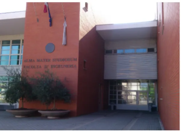
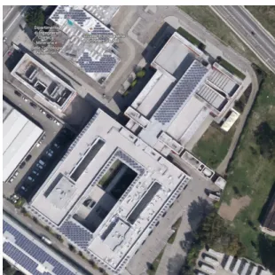
Figure 5. Top: School of Engineering and
Archi-tecture main entrance; bottom: site view: School of Engineering and Architecture in the middle.
This project was born from the interest in the situa-tion of the existing School of Engineering and Ar-chitecture Campus in Via Terracini, Bologna. It is the second Campus of this School and is located out of the city center, in a quite isolated suburb of Bologna, intercluded between the railway lines and rural area (Fig.5).
It is especially difficult to reach for students, who are mainly used to live in the city center. A student without a car has to reach it either by bus (only a couple of bus lines available) or by bike (bicycle paths are not continuous and even dangerous in some points). But the worst part is that this place is uninviting by itself as it has no adequate services and facilities to sustain the local activities, except for some little insufficient activities.
A major expansion of this University Campus might take place there in the near future, but, still, the current situation is unsustainable: hundreds of students, researchers and teachers have spent years working and studying there.
Moreover, the existing building mainly comprises offices, laboratories, libraries and classrooms but it is noticeable the fact that in a such isolated district, the University building has just one, small cafeteria. It serves as café and canteen at the same time only during lunch hours. In there, people can have their meals and drinks, but the space is usually crowded and not comfortable. There is a small green area outside with a gazebo, but it is not sufficient, es-pecially when outside it is really cold or too warm (Fig. 6).
The idea
There is no one unique way to solve all the men-tioned issues. Of course this looks as the result of a temporary situation, waiting for the planned big Campus extension; in reality, this building has been in operation for almost ten years and, still, students do not have basic comforts such as a place where to relax and calmly have their meals.
What can architecture do in this cases? If we assume that we cannot create a completely new masterplan or make big urban changes, only the small-scale in-tervention seems to do the trick.
The existing building is composed of an assemblage of mono-functional rooms were students can per-form only the prescribed tasks, with no possibility of deviation. In the classrooms they can only attend lessons, in libraries they can only study, in the café-canteen they can only eat and so on. The rest of the space is connection between these functional units, that is: corridors and low quality, resulting space. This is the opposite of what a productive environ-ment should look like. According to L.Malcic:
Figure 6. Right: mono-functional spaces in the ex-isting building; from the top: gazebo, classroom, café, corridors. Left: Existing building perspective from East.
“Workplace designers need to keep in mind that psycholo-gists believe the three basic human requirements are security, identity and stimulation. […] With this in mind, it will be important to create micro-environments that help people to control their own spaces. […] More simply, they can be al-lowed to choose their own chair.” [N5]
The perfect work environment should differentiate, create variability and stimulation. We have already discussed the importance and possibilities of het-erogeneous environments in Chapter 1.
In conclusion, the idea is to design a new space for University students where they can relax, study, have their meals and socialize. It will become an informal shelter from long lesson hours and crowded corri-dors and, at the same time, a sort of hub of new social interactions where people will be able to meet and have the chance to exchange ideas, experiences and, ultimately, develop creativity and innovation.
4.2 | Spatial organization
The chosen location for this new Pavilion is on top of the existing building: in this way, the new struction does not occupy new land; on the con-trary, it gives new function to an unused terrace, eas-ily accessible form two internal stairs and elevators (Fig. 8). This is a privileged location for the views it offers of the surroundings.
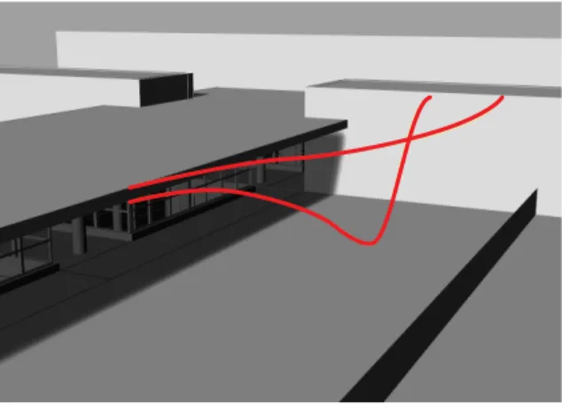
The terrace is situated exactly on top of the main classrooms. The space is interrupted by three full height internal glazed bodies which let light come inside the building. In the middle, along the longi-tudinal symmetry axis, a long, white framed struc-ture and roof dominates the terrace and the whole building. In North/East direction, but in a lower position, there is another outdoor space commonly used by students during breaks (Fig. 8 C). Our idea is to connect this space with the pavilion by means of a new external stair. In this way, both internal and external accesses are guaranteed and the terrace can be visited independently from the main building opening hours.
Figure 7. Right: mono-functional spaces in the ex-isting building; from the top: gazebo, classroom, café, corridors. Left: Existing building perspective from East.
+0.00 -4.55 -6.00 40.6 42.0 56.4 65.8 25.2 -1.92 -1.92 A B C D
Figure 8. Views of the terrace, outlined in light blue the project location
A
B
C
+0.00 -4.55 -6.00 40.6 42.0 56.4 65.8 25.2 -1.92 -1.92
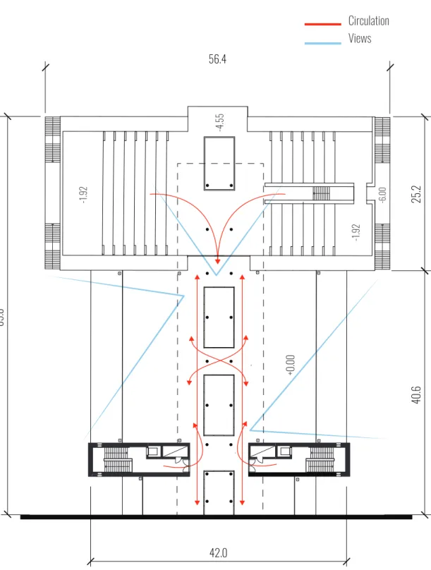
Figure 9. In red basic circulation and existent ac-cess system plus a new one designed to connect the terrace with the rest of outdoor space ; in light blue the views;
Views Circulation
40.6 42.0 56.4 65.8 25.2 Winter Summer
Figure 10. Solar study; orientation and existing grids 40.6 42.0 56.4 65.8 25.2 40.6 42.0 56.4 65.8 25.2
+
40.6
42.0 56.4
25.2
Pavilion part 2 Pavilion part 1
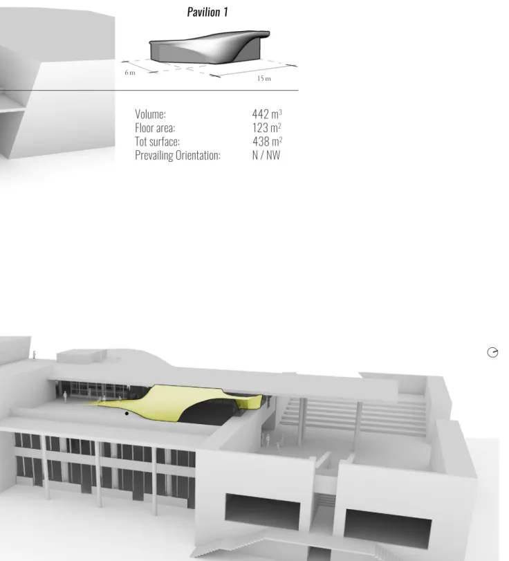
Figure 11. Lines in plan, elevation and 3d follow exitent geometry and orientation considerations.
Pavilion 2 17 m 8.5 m Volume: 442 m3 Floor area: 140 m2 Tot surface: 454 m2 Prevailing Orientation: S / SE
Pavilion 1 Volume: 442 m3 Floor area: 123 m2 Tot surface: 438 m2 Prevailing Orientation: N / NW 15 m 6 m
4.3 | Corrugations
Corrugations arise from an algorithm inspired by differential growth mechanisms of biological tissues in general and how the generated excess surface can create new interesting arrangements in space. The starting point is a thin surface of variable shape and curvature represented by a triangular mesh in the digital model. Each mesh vertex is the equiva-lent of a cell in the tissue and can be considered as a sort of moving particle constrained to stay on the mesh itself.
Internal forces
Internal forces make the mesh behave as an elastic membrane and help keeping it consistent and avoid-ing self-intersection.
Elastic force is represented by springs along the mesh edges: they connect the points and tend to keep them at a certain relative distance from each other. Parameters influencing this kind of force are the springs rest length and the springs strength.
Repulsion force prevents the mesh from self-intersect-ing or overlappself-intersect-ing.
Subdivision rule
Then, a rule is developed in order to subdivide mesh faces and consequently multiplicate mesh vertices. Changing the mesh topology in this way allows to simulate new cells generation. (Fig. 13)
The process is structured in cycles: after each sub-he process is structured in cycles: after each sub-division, the mesh is allowed to relax according to internal elastic/repulsion forces taking place along the edges. (Fig. 14)
Feedback
Then, a feedback mechanism selects the faces to be subdivided next, depending on environmental features and the loop starts again. The feedback influences the ridges according to aesthetic, func-tional, energetic, lighting and /or structural criteria, depending on the considered position.
ALPHA CYCLE
BETA CYCLE (relaxation)
Selection & subdivision
(feedback)
Figure 13. Top: subdivision rule; bottom: scheme of algorithm cycles
Figure 14. Process example
Figure 15. Process results. Bottom: force flow analysis with Karamba on the surface and corrugations
On the structural point of view, composite technol-ogy allows almost every possible form and shape. Addind layers to the FRP or changing its fiber di-rection can make it resist to all possible loads with-out affecting the shape. Although, on big shells like these, instability is possible, that is why double cur-vature geometries are useful. While double curva-ture stabilizes the geometry of the shell, ridges can concentrate in areas of higher deformation in order to locally stiffen the surface. An initial evluation of expected principal stress distribution and force field has been used to inform the ridges directions.
4.4 | Energy
A series of dynamic energy simulations are carried out to assess the energy performance of the Pavil-ion.
The used software is Energy Plus, with a series of plugins that allow its connection with Rhinoceros. These are Grasshopper plugins called Ladybug and Honeybee. With these tools, it is possible to use the Grasshopper interface to set up all the required data in order to carry out the energy simulation.
Thermal zones
The pavilion is considered autonomous, that is, its systems are not connected or dependent by the ex-isting ones. It is divided in four different zones: the parts under the two shells of the pavilion and other two resultant spaces. Only the first two zones are conditioned.
The overall internal space, anyway, is all open, with no walls or partitions. That is why some “air walls” have been used to separate the zones. Under the floor, the existing building is an already conditioned space, so dispersions are considered only through the external surfaces which are not adjacent to the existing building.
A series of context surfaces, included the existing photovoltaics, are added to calculate exact sun shad-ing on the zones (Fig.16 b).
Surface types and construction
Each zone has been decomposed in its boundary surfaces. For each of them a type has been de-fined: common types are “wall”, “window”, “roof ”, “floor” and so on.
Moreover, each surface has its own construction and boundary conditions.
Schedules
Schedules have been created to reflect students habits during the day. The pavilion is closed on Sun-day, so in that day occupation is zero. Important schedules are occupancy, occupancy activity, light-ing, equipment, infiltration and ventilation.
System
A VRF system with heat pump is completely au-tonomus and serves the pavilion when needed, thanks to a system of sensors. Moreover, occupants can control set points and adapt their environment locally.
The most critical situation is during the summer sea-son, so a venitilation system has been developed in order to naturally refrigerate during the night.
Figure 16. a: Zones in the energy model; b: zones with context shading.
a
Figure 17. a: Examples of comfort maps (at 11:00
and 18:00 , 15th July) showing operative tempera-ture of pavilion 1. b: cooling loads for the first pa-vilion the 15th of July.
Figure 18. a: Averaged inner surface temperature in January ; b: averaged inner surface temperature in July; c: potentiality of corrugation to reduce surface temperature by means of self-shadng
a
b
Scala 1:10
4.5 | Final views
Scala 1:10
Figure 19. a: detail of closure at the corner of the
sandwich FRP shell, scale 1:2; b: detail of the base of the sandwich shell, scale 1:10
Scala 1:2
a
72 | The Pavilion +0.00 +0.30 +0.00 +0.30 +0.00 +0.00 +0.00 +0.00 +0.00 -4.55 -1.92 -1.92 -1.92 -6.00 40.6 42.0 56.4 25.2
Modulated corrugations | 73 +0.00 +0.30 +0.00 +0.30 +0.00 +0.00 +0.00 +0.00 +0.00 -4.55 -1.92 -1.92 -1.92 -6.00 40.6 42.0 56.4 25.2 Figure 20. Plan, scale 1:250
5.1 | Design
5.1.1 | 3D Model
Prototyping is an important step to start testing the possibilities of composite materials in architecture. In this research, a small part of the pavilion shell has been selected and adapted for fabrication. The idea is to test in a smaller scale and with a lower budget approximately the same workflow, techniques and know how that can be used for the entire pavilion fabrication off-site. According to functional and aesthetic considerations, a part particularly suitable for fabrication is the one shown in Figure N. A scale of 1:2 has been chosen for this prototype. There-fore, a part of the shell 1.2m wide and 2.4m large corresponds to a 0.6m x 1.2m fabricated panel. The prototype, as well as the pavilion, is fabricated as a sandwich shell with fiber reinforced polymers at both sides. The external side is corrugated and made of carbon FRP and then coated with white gelcoat. The internal laminate, instead, is made of glass FRP and coated with a very thin layer of white gelcoat. Inside the polyurethane filling there are some sys-tems and a LED lighting system. The latter is placed adjacent to the GFRP laminate, so that light can pass through it, exploiting the typical translucency of glass fiber reinforced polymers. This is the rea-son why internal coating has to be really thin, in or-der to let the light come out and create a glare effect in the evening hours.
Figure 21. Bottom: portion of shell to prototype. Right: extracted 3d model for fabrication in scale 1:2 and relative thickness map.
Scale 1:2
2.93 cm
Carbon fiber reinforced laminate
Integrated systems
PUR foam
LED lighting system
Glass fiber reinforced laminate
Figure 22. Exploded view of the sandwich panel. Additional white coating will be applied on both sides.
a
b
5.1.2 | Mould model
Figure 23. a: Mould for the CFRP part; b: Two molds coupled, ready for PUR injection; c: Mould for the GFRP part.
After some reasoning on the best production meth-od to choose, hand lay-up has been chosen as the most feasible in terms of fabrication possibilities and time/cost constraints.
Prepreg carbon fiber textiles would have been a good choice in terms of ease of lamination, me-chanical properties, efficiency and aesthetics of the final component, but that would have required the use of an autoclave and, in conclusion, would have been too expensive. Another method would have been resin infusion, but the two laminates have dif-ferent shapes and that would have required a cus-tom filling panel with variable thickness.
Therefore, two moulds have been designed for hand lay-up of each FRP composite face (Fig.N a, c). Moreover, they have a shape that is studied specifically for allowing their overlapping, creating a closed block (Fig.N b). This box will have some holes to pour polyurethane inside the internal cavity once closed. PUR will expand and eventually escape from the same holes when it will have filled all the internal space.
5.2 | Fabrication
The prototype has been fabricated with the help of two companies based in Emilia-Romagna, Italy: Idesco for the moulds design and fabrication and Stilplast for composites production. Therefore, the fabrication process has involved two main stages which are illustrated below.
Mould production
Mould production is done by Idesco, a company based in Forlì, Italy.
The geometries of the two moulds are digitally gen-erated starting from the initial 3d model as described above. The company chooses Medium Density Fi-berboard (MDF) as mould material.
Then, the rough molds are assembled and milled by means of a CNC machine. Consequently, after a sanding with P220 sandpaper, a polyester primer is applied.
After the necessary treatments, the moulds are cou-pled, stacked together and prepared for transporta-tion to the second company which will take care of the FRP composites production by means of hand lay-up.
Figure 24. Top: MDF Mould before milling; bot-tom: CNC machine milling the two moulds.
Figure 25. Top: Sanding with P220 sandpaper; bot-tom: final moulds.
Figure 26. Top: moulds with polyester primer; bot-tom: packing of the heavy moulds to be transported to the next phase
Composite production
The second stage of production has been carried out in collaboration with Stilplast, a company based in Ravenna, Italy.
The first step is to treat the moulds surface with a release agent to help demoulding and avoid resin absorbtion by the mould; after that, we apply white gelcoat only to part of the first mould (the one for the carbon FRP composite). The day after, when gelcoat is dry, we start hand lay-up. CRFP is lami-nated in the first, corrugated mould, while GFRP is produced in the second mould. After a thin layer of non-fibrous gelcoat applied only to the sharper edg-es, dry reinforcement textiles are manually placed in the moulds with subsequent application of cata-lyzed resin. The technician impregnates fibers with a uniform distribution and right amount of resin and then uses rollers to debulk the various layers. In this stage, the laminator’s skills are essential for the good quality of the final product. After the resin has cured at room temperature, system pipes are placed over the carbon mould, while a LED light strip is secured to the inner surface of the glass FRP. Con-sequently, the two moulds are coupled, secured to-gether and placed in vertical position. Polyurethane in liquid solution is poured from the top inside the internal cavity between the moulds through three holes. In a few minutes it expands and escapes from the same holes at the top. Then, the prototype is demoulded. The glass FRP side is spray-coated with a thin layer of white gelcoat, so that when the LED is on, light can pass through the glass FRP skin and gelcoat. The carbon FRP, instead, is partially coated with transparent gelcoat. The borders are cleaned up and final refinements are made.
Figure 27. Hand lay-up of glass fiber reinforced polymer
Figure 28. Top: after white gelcoat has been applied directly to the mould and is already dry, a special non-fibous gelcoat is applied only to the sharper edges, which are difficult to be reached by the roller; bottom: part of carbon fibre reinforced polymer ap-plied over gelcoat.
Figure 29. Right: LED is attached to the inner face of the GFRP laminate; bottom: the two moulds are coupled.
Figure 30. Left: The two moulds are fastened and put in vertical position; bottom: polyurethane is poured inside the internal cavity from the top holes.
Figure 31. Right: Glass FRP and transparency test with thin layer of white coating; bottom: GFRP af-ter opaque gel-coating, LED off.
Figure 32. Left: Carbon FRP, partially coated; bot-tom: CFRP after transparent lucid gel-coating.
![Figure 1. a: initial basic ball of cells; b: examples of different results of Cellular Forms by Andy Lomas [10]](https://thumb-eu.123doks.com/thumbv2/123dokorg/7436737.100032/41.786.496.673.143.1069/figure-initial-examples-different-results-cellular-forms-lomas.webp)
![Figure 3. Floraform by Nervous System, differen- differen-tial growth. a: growth from point; b: point expan-sion; c: edge expanexpan-sion; d: adaptive subdiviexpan-sion; e: collision; f: geodesic distance [11]](https://thumb-eu.123doks.com/thumbv2/123dokorg/7436737.100032/43.786.427.723.143.557/floraform-nervous-differen-differen-expanexpan-adaptive-subdiviexpan-collision.webp)
![Figure 4. Florescence Ornata 2, Floraform sculp- sculp-tures by Nervous System. Nylon 3d printed by Se-lective Laser Sintering [11]](https://thumb-eu.123doks.com/thumbv2/123dokorg/7436737.100032/44.786.38.758.604.1086/figure-florescence-ornata-floraform-nervous-printed-lective-sintering.webp)