to my Family, where Life begins and Love never ends, to my Father, on the other side of the street.
1
Table of Contents
Chapter 1 Introduction ... 17
1.1. The Use of Composite Materials for Civil Applications ... 17
1.2. Definition of Composite Material ... 18
1.3. Brittle-Matrix Composites: TRC and FRCM ... 21
1.3.1. Cementitious Matrix Reinforced with Short Dispersed Fibers ... 22
1.3.1.1. Fiber Reinforced Concrete/Cement (FRC) ... 22
1.3.1.2. Engineered Cementitious Composite (ECC) ... 24
1.3.2. Cementitious Matrix Reinforced with Continuous Fibers ... 24
1.3.2.1. Textile Reinforced Concrete (TRC) ... 24
1.3.2.2. Fiber Reinforced Cementitious Matrix (FRCM) ... 27
1.3.2.2.1. Constituent Materials: Matrices and Fabrics ... 28
1.3.2.2.1.1. Fabrics ... 30 1.3.2.2.1.1.1. Glass Fibers ... 30 1.3.2.2.1.1.2. Carbon Fibers ... 32 1.3.2.2.1.1.3. Aramid Fibers ... 34 1.3.2.2.1.1.4. PBO Fibers ... 35 1.3.2.2.1.1.5. Basalt Fibers ... 36 1.3.2.2.1.1.6. Steel Fibers ... 36
Chapter 2 Evolution of reinforcement systems: from FRP to FRCM and SRG ... 38
2.1. Introduction ... 38
2.2. The Reasons of Structural Reinforcements ... 39
2.3. Evolution in Reinforcement Systems ... 40
2.4. Composite Materials Advantages... 41
2.5. Fiber Reinforced Polymer (FRP) ... 42
2.5.1. Applications of FRP in Civil Structures ... 43
2.5.1.1. Precured Systems ... 44
2
2.5.2. FRP Composite Materials in Structural Reinforcement ... 45
2.5.3. American Guideline ACI 440 ... 46
2.5.4. Italian Government Guidelines for Identification, Qualification and Acceptance Control ... 48
2.5.4.1. Scope of the Guidelines ... 49
2.5.5. The Limits of Traditional Composite Systems: FRP Systems are not reliable ... 50
2.6. The New Frontier of the Reinforcement: FRCM Composite Materials . 51 2.6.1. Innovation of Inorganic Matrix ... 51
2.7. Behavior of FRCM and FRP Reinforcement Systems at High Temperatures... 52
2.8. Post-cracking Ductility and Fire Resistance ... 53
2.9. The Properties of Reinforcement Systems for Seismic Adaptation of Structures ... 54
2.10. Durability Based on Humidity and Ambient Temperature ... 55
2.11. A New Tool in the Repair Toolbox: Steel Reinforced Grout ... 57
2.11.1. SRG Composite Systems ... 57
2.11.2. Properties of the SRG Composite Systems ... 58
2.11.3. Physical-geometric Characteristics ... 59
2.11.3.1. Mechanical Characteristics ... 61
Chapter 3 Characterization testing of FRCM and SRG ... 62
3.1. Introduction ... 62
3.2. Physical and Mechanical Properties of FRCM and SRG Composite Material ... 65
3.2.1. Mortar Matrix Compressive Strength ... 66
3.2.2. Composite Continuous Tensile Strength ... 66
3.2.3. Composite Lap Tensile Strength ... 66
3.2.4. Composite Interlaminar Shear Strength ... 67
3.2.5. Composite Bond Strength ... 67
3.3. Mechanical Testing of FRCM and SRG Composite Material ... 68
3
3.3.2. Expected Tensile Stress-Strain Curve ... 71
3.3.3. Composite Lap Tensile Test ... 73
3.3.4. Composite Interlaminar Shear Test ... 74
3.3.5. Composite Bond Test ... 76
3.3.5.1. Lap Shear Test ... 76
3.3.5.2. Pull-off Test ... 79
Chapter 4 Testing Procedures for the Uniaxial Tensile Characterization of Fabric-Reinforced Cementitious Matrix Composites ... 82
4.1. Tensile Mechanical Behavior ... 82
4.2. Tensile Test Methods for FRCM ... 85
4.3. Idealized Trilinear Stress-Strain Curve ... 87
4.4. Fiber to Matrix Bonding ... 88
4.5. Experimental Program ... 90
4.5.1. FRCM Composites Used during the Investigation ... 90
4.5.2. Fabric Reinforcement ... 91
4.5.3. Inorganic Matrix ... 93
4.5.4. Specimen Geometry and Preparation ... 94
4.6. Test Set-up ... 94
4.6.1. Gripping ... 94
4.6.2. Instrumentation ... 95
4.7. Experimental Results ... 96
4.7.1. Clevis Grip on One-Layer Specimens ... 96
4.7.2. Clamping Grip on One-Layer Specimens ... 97
4.7.3. Clevis Grips on Two-Layer Specimens ... 101
4.7.4. Clevis Grips on Spliced Specimens ... 102
4.7.5. Clamping Grips on Spliced Specimens ... 103
4.8. Influence of Different Gripping Methods ... 103
Chapter 5 Compressive Tests ... 105
5.1. Introduction ... 105
4
5.2.1. Specimen Geometry and Preparation ... 105
5.2.2. Test Set-Up ... 107
5.3. Compressive Strength ... 108
5.4. Results ... 108
5.4.1. Hydralic Lime Based Mortar (GCF) ... 108
5.4.2. Cement Based Mortar (GLT) ... 113
Chapter 6 Tensile Tests ... 118
6.1. Introduction ... 118
6.2. Mechanical Behavior of SRG in Tension ... 118
6.3. Materials ... 119
6.3.1. Textile Reinforcements ... 120
6.3.2. Cementitious Matrix ... 121
6.4. Specimen Preparation and Test Set-Up ... 122
6.4.1. Specimen Geometry and Preparation ... 122
6.4.2. Clamping Method ... 124
6.4.3. Instrumentation ... 125
6.5. Results ... 126
6.5.1. Tensile Tests of GLT-G6-1 Specimen... 126
6.5.2. GLT-G6 Series ... 130
6.5.3. GLT-G12 Series ... 132
6.5.4. GCF-G6 Series ... 135
6.5.5. GCF-G12 Series ... 137
Chapter 7 Interlaminar Shear Tests ... 141
7.1. Introduction ... 141
7.2. Specimen Preparation and Test Set-Up ... 142
7.2.1. Specimen Geometry and Preparation ... 142
7.2.2. Test Set-Up ... 142
7.3. Short-Beam Strength ... 144
7.4. Results ... 145
5
7.4.2. GCF-G12 Series ... 146
7.4.3. GLT-G12 Series ... 149
Chapter 8 Pull-off Tests ... 151
8.1. Introduction ... 151
8.2. Materials ... 151
8.2.1. Textile Reinforcements ... 152
8.3. Specimen Preparation and Test Set-Up ... 153
8.3.1. Specimen Geometry and Preparation ... 153
8.3.2. Test Set-Up ... 155 8.4. Bond Strength ... 156 8.5. Results ... 157 8.5.1. BTY-GCF-G6 Series ... 157 8.5.2. BTY-GCF-G12 Series ... 158 8.5.3. BTC-GLT-G6 Series ... 161 8.5.4. BTC-GLT-G12 Series ... 162 8.5.5. BTU-GCF-G6 Series ... 164 8.5.6. BTU-GCF-G12 Series ... 165 8.5.7. BTU-GLT-G6 Series ... 166
Chapter 9 Qualification parameters ... 169
9.1. Introduction ... 169
9.2. European qualification procedure ... 169
9.2.1. Direct tensile tests ... 169
9.2.2. Shear bond tests ... 171
9.3. Combination of the results and identification of qualification parameters...172
9.4. Differences between US standard AC434 and European procedure ... 173
9.5. The merge of US standard AC434 in the Design Code ACI 549 ... 176
9.6. Qualification parameters of tests results ... 176
6
Appendix: Stress vs Strain Curves of Tensile Tests ... 184
1. GLT-G6 Series ... 184 2. GLT-G12 Series ... 191 3. GCF-G6 Series ... 196 4. GCF-G12 Series ... 200 Bibliography ... 205 Acknowledgements ... 213 Ringraziamenti ... 215
7
Index of Figures
Figure 1.1 - Characteristic mechanical behavior of organic polymer matrix
composites [Callister & Rethwisch 2012] ... 20
Figure 1.2 - Comparison of behavior between carbon (CFRP) and glass (GFRP) composites, and steel [Callister & Rethwisch 2012] ... 20
Figure 1.3 - Graphic representation of brittle composite behavior [Callister & Rethwisch 2012] ... 21
Figure 1.4 - Typical stress-strain curve for ferrocement in tension [ACI 549-1999] ... 25
Figure 1.5 - Ferrocement boat hull built by Nervi, 1972 ... 26
Figure 1.6 - Typical sections of thin textile reinforce concrete (TRC) product with: a) several layers of 2D textile reinforcements, or b,c) one layer of 3D textiles [Naaman, 2010] ... 26
Figure 1.7 - Typical fabrics used as reinforcement in FRCM applications: a) carbon, b) PBO, c) glass, d) steel, e) basalt ... 29
Figure 1.8 - Glass fibers [Mapei website] ... 31
Figure 1.9 - Carbon fibers [Ruredil website] ... 32
Figure 1.10 - Aramid fibers [DuPont website]... 34
Figure 1.11 - PBO fibers [Ruredil website] ... 35
Figure 1.12 - Basalt fibers [Kerakoll website] ... 36
Figure 1.13 - Steel fibers [Kerakoll website] ... 37
Figure 2.1 - Connections between the structural elements [Ruredil book] ... 40
Figure 2.2 - Idealized stress-strain curves for construction materials [Karbhari, 2007] ... 42
Figure 2.3 - Qualitative comparison of constituent’s stress-strain relations [Mela, 2013] ... 43
Figure 2.4 - Change of flexural strength based on temperature [Ruredil book] ... 53
Figure 2.5 - Collapse mechanisms [Ruredil book] ... 55
Figure 2.6 - Flexural strength of FRCM based on temperature, relative humidity and days of exposure [Ruredil book] ... 56
8 Figure 2.7 - Flexural strength of FRP based on temperature, relative humidity and
days of exposure [Ruredil book] ... 56
Figure 2.8 – Shear strength of FRP based on temperature, relative humidity and days of exposure [Ruredil book] ... 56
Figure 2.9 - Ultra-High Strength Steel textile [Kerakoll catalogue] ... 59
Figure 2.10 - Textiles (a, b, c) and detail of cord/rope (d, e, f) of steel types G (galvanized steel cords, a, d), S (stainless steel cords, b, e), and R (stainless steel ropes, c, f) [De Santis et al, 2017] ... 60
Figure 3.1 - Gripping mechanism and typical specimen dimensions [AC434] .... 69
Figure 3.2 – Attaching of tabs by epoxy resin [Arboleda, 2014] ... 70
Figure 3.3 - The expected tensile stress-strain curve of an FRCM/SRG coupon specimen [AC434] ... 71
Figure 3.4 – Coupon with overlap length for composite Lap Tensile Test [Arboleda, 2014] ... 74
Figure 3.5 - Horizontal shear load diagram (Flat Laminate) [ASTM D2344] ... 75
Figure 3.6 - Typical failure modes in the Short Beam Test [ASTM D2344] ... 76
Figure 3.7 - Test set-up [Verre, 2014]... 77
Figure 3.8 - Failure modes in shear bond tests on externally bonded FRCM strengthening systems [Ascione et al, 2015] ... 78
Figure 3.9 - Typical force-slip curves observed in shear bond tests on externally bonded FRCM strengthening systems related to failure modes A, B, and C (a), failure mode D and E (b), failure mode F (c) [Ascione et al, 2015] ... 79
Figure 3.10 - Schematic of Setup to Test Material Applied to Substrate [ASTM C1583] ... 80
Figure 3.11 - Schematic of failure modes [ASTM C1583] ... 81
Figure 4.1 - Stress-strain diagram of textile reinforced concrete under uniaxial loading [Heg2004a, Jes2004a] ... 83
Figure 4.2 - Tension stiffening under uniaxial loading [Hegger et al. 2004]... 83
Figure 4.3 - Stress-strain bilinear curve of FRCM under uniaxial tension [AC434] ... 84
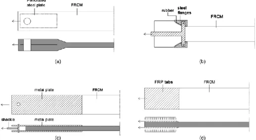
Figure 4.4 - Test setups: (a) Steel plate inside specimen; (b) Steel flanges; (c) Clevis (adhesive tension and shear) grip; (d) Clamping grips [Arboleda et al, 2016] ... 85
9
Figure 4.5 - Clevis grip [Arboleda, 2014] ... 86
Figure 4.6 - Clamp grip [Arboleda, 2014] ... 87
Figure 4.7 - Idealized stress-strain curves: (a) stand-alone fabric; (b) clamped FRCM; (c) pinned FRCM [Arboleda et al, 2016] ... 88
Figure 4.8 - Graphic representation of the fiber slip phenomena [Banholzer et al, 2006] ... 89
Figure 4.9 - (a) PBO-FRCM system; (b) C-FRCM system [Arboleda et al, 2016] ... 91
Figure 4.10 - Fabric geometry: (a) PBO; (b) glass; (c) coated glass; (d) carbon; (e) coated carbon (dimensions in millimeters) [Arboleda et al, 2016] ... 92
Figure 4.11 - Tensile test setup: (a) clevis grip; (b) clamping grip [Arboleda et al, 2016] ... 95
Figure 4.12 - Stress-strain curves with clevis grip of different FRCM materials [Arboleda et al, 2016] ... 97
Figure 4.13 - Stress-strain curves with clamping grip of different FRCM materials [Arboleda et al, 2016] ... 100
Figure 4.14 - PBO-FRCM single layer behavior with the different test setups [Arboleda et al, 2016] ... 101
Figure 4.15 - C-FRCM single layer behavior with the different test setups [Arboleda et al, 2016] ... 101
Figure 4.16 - cC-FRCM: two ply versus one ply [Arboleda et al, 2016] ... 102
Figure 4.17 - PBO-FRCM lap splice behavior with the different test setups [Arboleda et al, 2016] ... 103
Figure 5.1 - Cube molding for compressive strength of mortar tests ... 106
Figure 5.2 - Cube de-molding for compressive strength of mortar tests ... 106
Figure 5.3 - Compressive test set-up ... 107
Figure 5.4 - Schematic of typical fracture patterns ... 108
Figure 5.5 - Representative failure modes of cubes made of GCF at curing time of three days ... 109
Figure 5.6 - Representative failure modes of cubes made of GCF at curing time of seven days ... 110
10 Figure 5.7 - Representative failure modes of cubes made of GCF at curing time of
fourteen days ... 111
Figure 5.8 - Failure modes of cubes made of GCF at curing time of twenty-eight days ... 112
Figure 5.9 - Representative failure modes of cubes made of GLT at curing time of three days ... 113
Figure 5.10 - Representative failure modes of cubes made of GLT at curing time of seven days ... 114
Figure 5.11 - Failure modes of cubes made of GLT at curing time of fourteen days ... 115
Figure 5.12 - Representative failure modes of cubes made of GLT at curing time of twenty-eight days ... 116
Figure 6.1 – Stress-strain behavior of FRCM composites subjected to tensile test [Carozzi et al, 2015] ... 119
Figure 6.2 - Galvanized UHTSS textile: a) Sheet G6; b) Sheet G12 ... 120
Figure 6.3 - Mortar matrices: a) Mineral Mortar (GLT); b) Natural Hydraulic Lime Mortar (GCF) [Kerakoll catalogue] ... 121
Figure 6.4 - Coupon size ... 122
Figure 6.5 - Clevis-type grip [Arboleda, 2014]... 125
Figure 6.6 - Tensile test set-up ... 126
Figure 6.7 - Load-Strain Curve for coupon GLT-G6-1 ... 127
Figure 6.8 - Failure mode of coupon GLT-G6-1 subject to tensile test: (a) first and multiple cracks in the mortar; (b) enlargement of first crack; (c) ultimate failure. ... 128
Figure 6.9 - Stress-Strain Curve for coupon GLT-G6-1 ... 129
Figure 6.10 - Stress-Strain Curve for coupon GLT-G6-2 ... 130
Figure 6.11 - Stress-Strain Curve for coupon GLT-G12-1 ... 132
Figure 6.12 – Representative failure mode of coupons GLT-G12 subject to tensile test ... 134
Figure 6.13 - Stress-Strain Curve for coupon GCF-G6-1 ... 135
Figure 6.14 - Representative failure mode of coupons GCF-G6 subject to tensile test ... 137
11
Figure 6.15 - Stress-Strain Curve for coupon GCF-G12-1 ... 138
Figure 6.16 - Representative failure mode of coupons GCF-G12 subject to tensile test ... 140
Figure 7.1 - Interlaminar test setup [ASTM D2344]... 143
Figure 7.2 - Interlaminar test set-up ... 143
Figure 7.3 - Typical Failure Modes in the Short Beam Test: a) Interlaminar Shear, b) Flexure in compression, c) Flexure in tension, d) Inelastic Deformation [ASTM D2344] ... 144
Figure 7.4 - Failure mode of the specimens GCF-G6-1... 146
Figure 7.5 - Failure modes of the GCF-G6 specimens ... 146
Figure 7.6 - Failure mode of the specimens GCF-G12-2... 148
Figure 7.7 - Failure modes of the GCF-G12 specimens ... 148
Figure 7.8 - Failure mode of the specimen GLT-G12-2 ... 149
Figure 7.9 - Failure modes of the GLT-G12 specimens ... 150
Figure 8.1 - Textile reinforcements: a) Steel Sheet G6; b) Steel Sheet G12 ... 152
Figure 8.2 - Mortar Matrices: a) Mineral Mortar (GeoLite); b) Natural Hydraulic Lime Mortar (GeoCalce Fino) [Kerakoll catalogue] ... 152
Figure 8.3 - Specimens preparation: a) Cleaning of specimens by any debris, b) Reinforcement applied on clay bricks, c) Reinforced concrete blocks and d) Reinforced concrete masonry units ... 154
Figure 8.4 - Steel disks attached on a) clay brick, b) concrete masonry unit and c) concrete block ... 154
Figure 8.5 - Pull-off test set-up ... 155
Figure 8.6 - Possible failure modes of pull off test: A) Failure in the substrate, B) Bond failure at the FRCM-substrate interface, C) Failure at the mortar-fabric interface, D) Bond failure at the epoxy-FRCM [Donnini, 2016] ... 156
Figure 8.7 - Failure modes of the BTY-GCF-G6 series... 157
Figure 8.8 -Failure modes of the BTY-GCF-G12 series ... 159
Figure 8.9 - Failure modes of the BTC-GLT-G6 series ... 161
Figure 8.10 - Failure modes of the BTC-GLT-G12 series ... 163
12 Figure 9.1 - Typical stress-strain response curve of FRCM systems under tensile loading [Ascione et al., 2015] ... 170 Figure 9.2 - Failure modes in shear bond tests on externally bonded FRCM strengthening systems [Ascione et al., 2015] ... 172 Figure 9.3 - Combination of the results of shear bond tests (a) and direct tensile tests (b) for the identification of qualification parameters [Ascione et al., 2015]... 173
13
Abstract
Composites materials are continuously evolving and their use for the repair and retrofit of civil structures has become a common practice among the engineering community. Fabric Reinforced Cementitious Matrix (FRCM) and Steel Reinforced Grout (SRG) systems represent a new repair methodology for structural strengthening and rehabilitation, including historical restoration; they are becoming a viable alternative to FRP, whenever the project conditions do not allow the use of organic polymer based composites.
FRCM is described by the American Concrete Institute (ACI) committee 549 as a composite material consisting of a sequence of one or more layers of cement-based matrix reinforced with dry fibers in the form of open single or multiple meshes that, when adhered to concrete or masonry structural members, forms a FRCM system. FRCM and SRG are usually constituted by dry fabrics and it is proved that the bond at the matrix-fibers interface is not optimal, since only the external filaments are in contact with the matrix and able to transfer the load, while the inner filaments slip due to the low friction between the fibers.
To this end, an experimental program was undertaken to investigate the mechanical behavior in order to determine the material properties needed for design and to evaluate its performance in environmental conditions.
Two new fabric meshes impregnated by means of two several matrices were selected for this research. The fabric meshes are steel textiles constituted by cords of Ultra High Tensile Strength Steel (UHTSS) micro-wires with different mass density, namely G6 (600 g/m2) and G12 (1200 g/m2); while the matrices are a cement-based mortar, GLT, and a lime-based mortar, GCF.
This work aims to advance the state of cement-based composite materials testing methodology with a goal towards standardization and it is presented through two parts, which in turn divided in four chapter.
First Part reports the following chapters:
1. An introductory chapter, which gives a brief overview of composites, focusing on the classification of brittle matrix composites in order to provide a contextual field within which FRCM and SRG are differentiated.
14 2. Second chapter provides to frame cement-based composite materials in an evolutionary context as reinforcement system. In fact, Fiber Reinforced Cementitious Matrix (FRCM) composites are an alternative to Fiber Reinforced Polymer (FRP) composites and they have gained some interest in the last decade. In particular, the need of effective, versatile and cost efficient strengthening methods has encouraged producers to develop and sell steel textiles for structural rehabilitation purposes, in other words Steel Reinforced Grout (SRG) systems.
3. Given the increased interest in the utilization of cement-based composite systems for structural retrofitting applications, their specifications need to be necessary. In third chapter, the development of acceptance criteria for masonry and concrete strengthening using Fabric-Reinforced Cementitious Matrix (FRCM) and Steel Reinforced Grout (SRG) composite systems has been discussed.
4. Experimental program, which investigates the tensile test method used to characterize FRCM material properties, specifically the load transfer gripping mechanism, namely clevis type grips and clamping grips.
Second Part presents the results of characterization experiments performed on SRG systems. In particular, tensile, interlaminar shear, bond and compressive tests were performed on specimens in control condition. Two types of steel fabrics, G6 and G12, and two types of mortars, GLT and GCF, have been used to produce a total of four SRG systems, namely GLT-G6, GLT-G12, GCF-G6 and GCF-G12. The purpose of second part is to evaluate the performance of SRGs and so to understand their mechanical behavior and the effectiveness and compatibility with concrete and masonry substrates. In addition, the preliminary considerations obtained from this thesis can be considered as first step toward the development of proper design formulae for characterization of SRG systems. Therefore, the following chapters show:
1. Compressive tests. Two types of mortar were chosen among those present on the market, specifically designed for structural reinforcement, namely cement based mortar (GLT) and hydraulic lime based mortar (GCF). Then, they were
15 casted in cubical molds of 50 mm side length according to standard requirements. After a curing time of three, seven, fourteen and twenty-eight days, they were tested with the help of a hydraulic type universal test frame. Finally, the maximum load carried by the sample during the test was recorded and the type of fracture pattern was noted. The primary mode of failure was compression of the cube resulting to be a cone like structure as desired. Based on the experimental tests presented, both the cement-based mortar, GLT, and the hydraulic lime-based mortar, GCF, meets the requirements of AC434. 2. Tensile tests. Rectangular coupons with nominal size 510 x 51 x 10 mm were
made in a flat glass mold by applying a first layer of cementitious mortar (5 mm), the fiber mesh and a second layer of cementitious mortar (5 mm). After a curing time of 28 days in humidity chamber, tests were performed using a screw driven universal test frame. Uniaxial tensile load was applied to all specimens by means of clevis grip setup. Load was applied under displacement control at a rate of 0.25 mm/minute and recorded by the load cell integrated in the testing machine. Axial deformation was measured using two extensometers with a 100 mm and 50 mm gauge length, placed mid-length of the specimen. The results of tests for each tested coupons are presented as tensile strength versus strain curves. Then, based on experimental results, maximum force, ultimate strength and strain, and cracked elastic modulus have been calculated. Finally, failure mode has been described for each tested specimens. Failure mode is not been equal for all specimens. In most cases, the collapse is due to the splitting of the matrix around the fiber cords with consequent slippage of fibers. However, the detachment of the tab from the coupon and the enlargement of cracks, which caused breakage of the specimen into several pieces, occurred as well.
3. Interlaminar shear tests. This test is a three-point bending test on short beam, where a transverse shear is induced in specimens with low support to specimen thickness ratios. This test method determines the apparent interlaminar shear strength of high-modulus fiber-reinforced composite materials. Specimens were machined from 330 x 508 mm panels with a diamond blade saw later a curing of 28 days in humidity chamber. Short beams were characterized by two
16 layers of fiber mesh embedded in two layers of 4 mm cementitious mortar. The fibers were also divided by another thin layer di mortar. A total of five tests per product under control ambient conditions were carried out. Finally, the peak load recorded during test, the ultimate strength computed as per standard requirement and the failure mode were reported. The systems packaged with G6 steel fabrics have presented a collapse due to the matrix cracking in the tension side, while in the case of the systems packaged with G12 steel fabrics, the primary mode of failure was interlaminar shear. Indeed, it has been observed the development of two cracks at fiber-matrix interface that propagated from the center of the specimen to the edge. The reason is because the G12 fabric has mass density higher than that of G6 textile and did not permit the complete penetration in the matrix. Therefore, the bond at fiber-matrix interface was not efficient.
4. Pull-off tests. In order to investigate the bond at the SRG reinforcement-substrate interface, 28 pull-off tests were carried out on several types of substrate, namely concrete blocks, clay bricks and cementitious masonry units. The reinforcement were applied onto the substrate, previously cleaned, for a minimum of 63 mm thick. Later 28 days of curing time, hexagonal cuts, perpendicular to the substrate of the specimen, were performed in order to circumscribe the disk used for testing according to standard requirements. Then, the steel disks were attached by epoxy to the reinforcement surface as a means to pull-off the circular area. Uniaxial tensile load was applied perpendicular to the test surface using a pull-off test machine. Tensile loading device was connected to the steel disk using a coupling fixture. Tensile load was applied to the steel disk until failure occurred. Finally, the ultimate load recorded during test, the ultimate strength computed as per standard requirement and the failure mode were reported. Main collapse mode of SRG composite is failure at reinforcement-matrix interface, so the density of fabric is an important parameter. In fact, the lower is the mass density and the higher is the bond strength. The reason is that the matrix can penetrate more easily between the bundles and so the bond increases.
17
Chapter 1
Introduction
1.1. The Use of Composite Materials for Civil Applications
Civil infrastructure facilities deteriorate due to aging, overuse, misuse, exposure to aggressive environments, and lack of maintenance. Throughout the world, conservation, maintenance, and upgrading the structural performance of existing structures is of fundamental, cultural, economic, and human safety importance. Rehabilitation, rather than demolition and reconstruction, is a feasible economic alternative. Moreover, extending the design life of infrastructure is a necessary sustainable decision, in particular when intervention involves infrastructure with historical significance, where many national regulations may prevent demolition. Structural retrofit involves upgrading or changing a structure to implement changes in its use, design needs, or regulatory requirements; while rehabilitation involves making structural repairs to damaged or weakened elements in order to bring them up to required safety standards. Material systems and methods for structural retrofit and rehabilitation include the installation of Fiber Reinforced Polymer (FRP) composite systems, steel plate bonding, section enlargement, installation of near surface mounted bars, and external post-tensioning. Typical structural elements to strengthen are beams, slabs, columns, and walls.
The use of FRP systems has become a common technique for strengthening reinforced concrete (RC) elements. Since then, numerous research studies have been conducted in order to analyze, study and comprehend the properties of these materials and their optimal uses. Despite all of their advantages, the FRP strengthening technique has some limitations including:
• Poor behavior of epoxy resins at temperatures above the glass transition temperature;
• Long term durability uncertainty;
• Inability to apply FRP on wet surfaces or at low temperatures;
• Lack of vapor permeability, which may cause damage to the concrete structures;
18 • Concern that the use of epoxy resins could be a toxic hazard to the installer.
An alternative solution is the replacement of organic with inorganic binders, i.e., use a composite made with a cement-based matrix, instead of an organic polymer matrix. One such solution is the development of Fabric Reinforced Cementitious Matrix composites (FRCM) that consist of a fabric in a cementitious matrix. The inorganic matrix (cementitious mortar) in FRCM does not fully penetrate and impregnate the fiber strands in the fabric. This is a significant factor affecting the mechanical behavior and performance of the FRCM composite and must be understood.
The use of composite materials for civil applications dates back to ancient times, when different materials were mixed together to obtain a new material with high performances. In fact, Egyptian and Mesopotamian builders used a mixture of mud and straw to create strong and durable buildings. In the modern era, concrete is the most common artificial composite material consisting of loose stones (aggregate) held with a cement-based matrix. However, concrete is a very strong material, but cannot bear tensile loading. Therefore, steel bars are often added to it in order to create a reinforced concrete that is able to endure to tensile stresses.
1.2. Definition of Composite Material
Nowadays, the definition of “composite materials” is universally acknowledged as a system, constituted by two or more material phases conveniently arranged, which provides mechanical performance and properties better than those of the constituent materials. One of the phases is dispersed and stronger, called reinforcement, another phase is continuous and weaker, called matrix. Classification of composites depends on the nature of the matrix and the reinforcement type can be particulates, short distributed fibers, and continuous fibers.
Based on the type of matrix, a general subdivision of the composites is showed as follows:
• PMC (Polymer Matrix Composite): thermoplastic (such as nylon) or thermoset (such as epoxy resins);
19 • BMC (Brittle Matrix Composite) divided into:
o Ceramic Matrix Composites; o Cementitious Matrix Composites;
o Not-Cementitious Matrix Composites, lime based mortar or geo-polymer matrix.
This overview is limited to polymer and brittle matrix composites only, in order to frame the context from within which FRCM composites are studied and can be better understood.
The mechanical behavior of fiber-reinforced composites is governed by a complex relationship between the material properties of the constituent materials, their volume fraction, the bond interface between them, and their orientation with respect to the load applied. For example, FRP, that is a polymer matrix composite, has a very strong interfacial bond with a fiber reinforcement strain limit lower than the strain limit for the epoxy matrix, (εf < εm). In this case, the longitudinal (fiber
parallel to direction of load) and transverse (fiber perpendicular to direction of load) elastic moduli, Elong and Etran, respectively, can be estimated using the rule of
mixtures model (Daniel & Ishai 1994), that states that each constituent material contributes to the composite properties in a manner proportional to their volume fraction.
Known the elastic modulus and volume fraction of the fiber, Ef and Vf, and the
elastic modulus and volume fraction of the matrix, Em and Vm, it can calculate:
𝐸𝑙𝑜𝑛𝑔 = 𝐸𝑓∙ 𝑉𝑓+ 𝐸𝑚∙ 𝑉𝑚 (1)
𝐸𝑡𝑟𝑎𝑛= 𝐸𝑓∙𝐸𝑚
𝐸𝑓∙𝑉𝑚+𝐸𝑚∙𝑉𝑓
(2)
Eq. 1 is used for estimation of the longitudinal modulus, where the fiber and matrix are assumed under same state of strain, and the composite will theoretically fail when the strain limit of the fibers is reached.
20 Eq. 2 is used for estimation of the transverse modulus where the fiber and matrix are assumed to be under same state of stress. Initially, the matrix and fibers deform elastically. Eventually, the matrix yields and deforms plastically but the fibers continue to stretch elastically (Callister & Rethwisch 2012). These relationships give rise to the nearly linear elastic characteristic stress-strain curve shown in Figure 1.1.
Figure 1.1 - Characteristic mechanical behavior of organic polymer matrix composites [Callister & Rethwisch 2012]
Figure 1.2 shows a comparison of the idealized mechanical behavior of carbon FRP (C-FRP) and glass FRP (G-FRP) composites, and steel to show that while PMCs have superior strength, once they reach their ultimate capacity, the fail exhibiting no yielding.
Figure 1.2 - Comparison of behavior between carbon (CFRP) and glass (GFRP) composites, and steel [Callister & Rethwisch 2012]
21
1.3. Brittle-Matrix Composites: TRC and FRCM
In brittle matrix composites (BMC), the matrix is either a ceramic or a cement-based material such as grout, mortar, or concrete that are typically porous and have a relative high compressive strength, but low tensile strength. The behavior of BMC is very different from polymer or metal composites and the rule of mixtures model usually cannot be applied because, for some BMCs, the interfacial bond between fiber and matrix is weaker and more complex or because the strain limit of the matrix is much lower than that of the fibers (εm << εf). In those cases, the matrix
starts to crack at its strain limit and instead, fibers debonding and slipping are the mechanisms that mitigate cracks localization. This is a desirable behavior as it leads to pseudo-ductility. Fibers in brittle matrices hinder the cracking (Callister & Rethwisch 2012) and allow the redistribution of stress, leading to improve both tensile capacity and toughness. An additional benefit is reduction in crack size. Referring to Figure 1.3, BMCs behave linear-elastically up to the tensile strength of the matrix. Then, as the stress increases, multiple cracks develop in the matrix and the stress is redistributed through the fibers, allowing the composite material to sustain additional strain. At this point, either strain-softening or strain-hardening behavior will develop depending on the amount of fibers and the quality of the interfacial bond.
Figure 1.3 - Graphic representation of brittle composite behavior [Callister & Rethwisch 2012]
In strain softening, the load resistance will decrease with continued strain, while in strain hardening, it will increase and multiple cracking will develop.
22 Composites materials are often classified based on the type of used matrix and on the geometry and arrangement of the fiber reinforcement. A brief overview of the general classification used for BMCs is:
• BMC (Brittle Matrix Composite): o Cementitious Matrix Composites:
➢ Short dispersed fibers: ❖ FRC, GRC, SFRC ❖ HPFRC, UHPFRC, SHCC ❖ ECC ➢ Continuous fibers: ❖ Ferrocement ❖ TRC, TRM, MBC ❖ FRCM, FRFRCM
o Ceramic Matrix Composites;
Composites made from ceramic matrices are in a different category in respect to cementitious matrix composites, because they are generally not used in the construction field, even if they share similar mechanical enhancement properties as Fiber Reinforced Concrete (FRC).
1.3.1. Cementitious Matrix Reinforced with Short Dispersed Fibers
Cementitious composites made with short dispersed fibers can be used in bulk or as thin elements. In the US, they are included in the domain of ACI Technical Committee 544 - Fiber Reinforced Concrete whose scope is to develop and report information on concrete reinforced with short, discontinuous, randomly dispersed fibers.
1.3.1.1. Fiber Reinforced Concrete/Cement (FRC)
Fiber Reinforced Concrete/Cement (FRC) is concrete or cementitious material reinforced with short and dispersed fibers that range in length to a maximum of 75
23 mm. ACI544 (2002) defines FRC as concrete made primarily of hydraulic cements, aggregates, and discrete reinforcing fibers. Fibers suitable for reinforcing concrete have been produced from steel, glass, and organic polymers (synthetic fibers). The matrix can be concrete, mortar or cement paste.
FRC has been classified by fiber content and mechanical behavior, likely because the first influences the latter. To this end, by fiber content (Mehta & Monteiro 2006), the following is considered:
• Low volume fraction (< 1 %). The fibers are used mainly to reduce shrinkage cracking. These fibers are used in slabs and pavements that have large exposed surface leading to high shrinkage crack. Dispersed fibers offer various advantages over steel bars and wire-mesh to reduce shrinkage cracks such as:
1) Fibers are uniformly distributed in three-dimensions making an efficient load distribution;
2) Fibers are less sensitive to corrosion than the reinforcing steel bars; 3) Fibers can reduce the labor cost of placing the bars and wire-mesh. • Moderate volume fraction (between 1 and 2 %). The presence of fibers at this
volume fraction increases the modulus of rupture, fracture toughness and impact resistance. These composites are used in construction methods such as shotcrete and in structures that require energy absorption capability, improved capacity against delamination, spalling and fatigue.
• High volume fraction (greater than 2 %). The fibers used at this level lead to strain hardening of the composite that can be used to enhance the performance of structural elements.
Naaman & Reinhardt (2006) proposed a FRC classification based on the stress-strain response of the material loaded in tension. Strain hardening FRC is called High Performance Fiber Reinforced Cement Composites (HPFRCC), Ultra High Performance Fiber Reinforced Cement (UHPFRC), and also Strain Hardening Cement Based Composites (SHCC).
Other terms commonly used for FRC materials based on fiber material used are Steel Fiber Reinforced Concrete or Cement (SFRC or SFRCC), Glass Fiber Reinforced Concrete or Cement (GRC or GFRC) and Multi-Scale
Fiber-24 Reinforced Concrete (MSFRC) that consists of a combination of different size fibers.
1.3.1.2. Engineered Cementitious Composite (ECC)
Engineered Cementitious Composite (ECC) is similar in composition to FRC, but has higher toughness in the form of pseudo-ductility. ECC contains water, cement, sand, fiber, and some common chemical additives. Coarse aggregates are not used as they tend to adversely affect the unique ductile behavior of the composite. A typical composition employs water/cement ratio and sand/cement ratio of 0.5 or lower. Unlike some high performance FRC, ECC does not utilize large amounts of fiber. In general, 2 % or less by volume of discontinuous fiber is adequate, even though the composite is designed for structural applications (Li & Kanda 1998). Applications of ECC range from structural reinforced concrete, precast concrete, and rehabilitation of structural components in both seismic and non-seismic regions (Li 2003).
1.3.2. Cementitious Matrix Reinforced with Continuous Fibers
Cementitious matrices reinforced with continuous fibers in the form of meshes, textiles, or fabrics with an open grid arrangement fall in the category of thin reinforced cementitious products and have also been called cement based laminates. In the US, they are included in the domain of ACI Technical Committee 549 - Thin Reinforced Cementitious Products and Ferrocement.
Two types of brittle-matrix composites reinforced with continuous fibers can be distinguished: Textile Reinforced Concrete (TRC) and Fiber Reinforced Cementitious Matrix (FRCM).
1.3.2.1. Textile Reinforced Concrete (TRC)
TRC is a composite material made of open-meshed textile structures and a fine-grained concrete. The technical textiles are mainly made of alkali resistant (AR)-glass and sometimes of other materials as carbon or aramid. They are placed in the main stress direction of the composite and leads to a high performance compared to randomly distributed short fibers in the already known glass fiber reinforced
25 concrete (GFRC). In addition, TRC is cost competitive material if used as thin cement composite products.
TRC can be considered as an evolution of the most ancient ferrocement, a composite material invented and patented around the forties by Pier Luigi Nervi. Ferrocement consists in a mortar or plaster reinforced by a series of metal meshes layers of small diameter held together by a limited number of steel rods such as rebars. Committee 549 of the American Concrete Institute (ACI) provided the following definition: “Ferrocement is a type of thin-wall reinforced concrete commonly constructed of hydraulic-cement mortar reinforced with closely spaced layers of continuous and relatively small-size wire mesh. The mesh may be made of metallic or other suitable materials”.
The mechanical behavior consists of a first linear stage until cracks start to form in the matrix, followed by a decrease in elastic modulus where cracks enlarge, until the steel yielding phase prior to failure (Fig. 1.4).
Its strength and lightness, combined with the possibility to be molded into complex shapes, made it ideal for such applications as hulls for boats, shell roofs and water tanks (Fig. 1.5).
26
Figure 1.5 - Ferrocement boat hull built by Nervi, 1972
An interesting definition of TRC is given by A. E. Naaman [1]:
“Textile reinforced concrete is a type of reinforced concrete commonly constructed of hydraulic-cement matrix reinforced with several layers of closely spaced continuous 2D textiles, or one or several layers of 3D textiles (Fig. 1.6). At least one textile layer should be placed near each of the two extreme surfaces of the resulting structure. The textiles may be made of polymer, synthetic, metallic, organic or other suitable materials. The fineness of the cementitious matrix and its composition should be compatible with the textile armature system. It is meant to encapsulate. The matrix may contain discontinuous fibers or microfibers of appropriate dimensions.”
Figure 1.6 - Typical sections of thin textile reinforce concrete (TRC) product with: a) several layers of 2D textile reinforcements, or b,c) one layer of 3D textiles [Naaman, 2010]
Another term commonly used for this composite is Textile Reinforced Mortar (TRM).
27 1.3.2.2. Fiber Reinforced Cementitious Matrix (FRCM)
Fiber Reinforced Cementitious Matrix (FRCM) is a composite system specifically designed for the repair and rehabilitation of concrete and masonry structures. It is an alternative to the existing repair technology such as steel plate bonding, welded steel meshes, section enlargement, external post-tensioning and FRP.
However, FRCM systems have recently emerged as a suitable method for strengthening concrete and masonry structures. It is a composite material consisting of one or more layers of cement-based matrix reinforced with fibers fabric. The cement-based matrixes are typically made of combinations of Portland cement, silica fume, and fly ash as the binder. The use of inorganic matrix allows overcoming some issues, typical of FRPs, such as limited temperatures and fire resistance, lack of vapor permeability and impossibility of application on damp surfaces. On the other hand, FRCM composites also have some drawbacks, as for instance a lower level of adhesion between the fabric and the matrix and a brittle behavior of the matrix itself (Table 1.1). Inorganic matrices may provide higher compatibility with the substrate, in particular in the case of ancient masonry construction (clay bricks, tuff, stone blocks). In addition, they offer better quality in terms of reversibility of the intervention and advantages in term of cost and time of installation, especially on irregular surfaces. The main difference between FRP and FRCM systems is the matrix used to bond the fibers. In fact, the fibers are embedded and fully impregnated within an organic matrix (epoxy resin) in the case of FRP, while the inorganic mortar is used for FRCM and is not able to fully penetrate between the fibers.
FRCM has also known as Fabric-Reinforced Fiber Reinforced Cementitious Mortar (FRFRCM), because the mortar matrix used can itself be reinforced with short dispersed fibers. However, this term is not common. When the mortar used is mineral-based matrix, FRCM composites can also be denominated as Mineral Based Composites (MBC).
28
Table 1.1 - FRCM and FRP: advantages and drawbacks
FRCM
(Fiber Reinforced Cementitious Matrix)
FRP
(Fiber Reinforced Polymer)
Advantages Drawbacks Advantages Drawbacks
Good compatibility with the concrete
or masonry substrate in terms of chemical, physical and mechanical properties The inorganic matrix is brittle and
so it cracks under tensile loads
Lightweight and ease of application
Not applicable and durable in moist
environment
Ease of installation as traditional plastering or trowel
trades can be used
Bond at the matrix-fibers interface not so strong as in FRP
systems
High stiffness and tensile strength
Health hazards for applicators Breathability of the
system, that allows air and moisture transport through
the matrix
Its mechanical characterization and
full-exploitation needs further studies
Resistance to corrosion and chemical attacks Low vapor permeability Good performance at elevated temperatures in addition to partial fire resistance It can be tailored to give the required mechanical properties in various directions High temperature and fire resistance (it needs thermal
insulation) Efficient in
aggressive environment such
as alkaline, water vapor and sea water environments
Difficult to recycle
Reversibility, essential for the conservation of historic structures
Irreversibility of the intervention
1.3.2.2.1. Constituent Materials: Matrices and Fabrics
The principal components of FRCM are the cementitious matrix and the structural reinforcement fabric. The former is typically a grout system based on Portland cement and a low dosage of dry polymers at less than 5 percent by weight of cement. In the case of historical structures, not-cementitious mortars, such as limed-based mortars may be used as binders.
29 a) Capacity of the cementitious matrix to impregnate the fiber strands [2], [3], [4],
[5];
b) Effective bond properties at interface fiber/matrix [6], [7], [8], [9], [10], [11], [12], [13], [14], [15];
c) Adherence of the cementitious matrix on concrete or masonry substrate [16], [17].
Fibers can be natural, produced by plants and geological processes; chemical, when the chemical composition, structure and properties are significantly modified during the manufacturing process; ceramic and metallic. Fibers used as reinforcement in civil applications are usually synthetic fibers, coming entirely from synthetic materials such as petrochemicals. The properties, the amount and the arrangement of the fibers have a great influence on the characteristics of the composite.
a) b) c) d) e)
Figure 1.7 - Typical fabrics used as reinforcement in FRCM applications: a) carbon, b) PBO, c) glass, d) steel, e) basalt
To ensure the durability of the composite material, fibers have to withstand the alkaline environment of the matrix without losing their properties. Fibers must also meet guarantee small relaxation under permanent load, good and constant adhesion between reinforcement and substrate, low cost and easy processing by textile machinery.
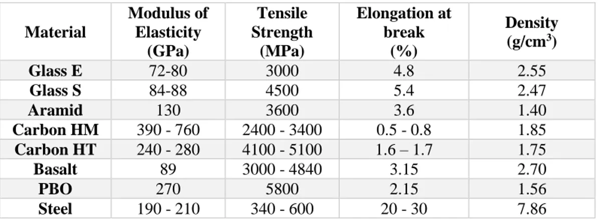
The mechanical properties of the most common fibers used in FRCM applications are shown in Table 1.2.
30
Table 1.2 - Properties of the most common fibers used as reinforcement
Material Modulus of Elasticity (GPa) Tensile Strength (MPa) Elongation at break (%) Density (g/cm3) Glass E 72-80 3000 4.8 2.55 Glass S 84-88 4500 5.4 2.47 Aramid 130 3600 3.6 1.40 Carbon HM 390 - 760 2400 - 3400 0.5 - 0.8 1.85 Carbon HT 240 - 280 4100 - 5100 1.6 – 1.7 1.75 Basalt 89 3000 - 4840 3.15 2.70 PBO 270 5800 2.15 1.56 Steel 190 - 210 340 - 600 20 - 30 7.86
The fabrics used in FRCM systems made by yarns woven in the two principal directions (primary direction, PD, and secondary, SD). The typical spacing of the yarns is less than 25 mm, and the total coverage area of the fiber mesh is less than 2/3 of total area. Besides, the geometry of the fabric plays an important role in determining the behavior of FRCM systems. Fabric architecture can enhance [18] or reduce [19] the FRCM performances. Cohen demonstrated that the warp and weft of yarns provides mechanical anchoring of the reinforcement such improving the overall composite performance. Richter shown that the transverse yarns strongly decrease the elastic modulus of the composite.
The properties of the yarns are strongly influenced by the size of the filaments. The size has a great influence on the quality of the adhesion between the filaments and it influences the load bearing performance. Furthermore, yarns can be coated with various types of polymers in order to enhance the mechanical behavior when coupled with inorganic matrices. The final purpose is to exploit better the high mechanical capability of the elementary fibers.
1.3.2.2.1.1. Fabrics
1.3.2.2.1.1.1. Glass Fibers
Glass fibers (Fig. 1.8) derive from an industrial fusion process of calcium oxide, silicon, magnesium, aluminum and boron that together form the tank. The oxides, melted at 1500 °C, are blended and abruptly cooled up to a temperature of 1200 °C. Thus melted glass obtained pass through special holes made on the bottom of platinum spinneret. The filaments are grouped together to form a braid or fiber
31 consisting of 204 filaments with an average diameter of about 10 μm and covered with a binder. Glass fibers are also available in the form of thin sheets, called mats, that can be made of both continuous long fibers and short fibers (25-50 mm) casually arranged in the plane and held together by a chemical binder.
Figure 1.8 - Glass fibers [Mapei website]
The commercially available glass fibers are: E-glass and Alkali-Resistant (AR). The former contain large amounts of boric acid and aluminate, the latter contain a small amount of zirconium oxide that is used to prevent corrosion from attacks due to the presence of alkali on cementitious materials. In general, they are all sensitive to water. Depending on the proportions of the raw materials used, products with different mechanical characteristics and performance are obtained. Seven different types of glass fibers can be found on the market (Table 1.3 - 1.4).
Table 1.3 - Glass fibers
Material Density (kg/m3) Elastic Modulus (GPa) Tensile Strength (MPa) Elongation at break (%) Glass fibers E 2550 70 3500 3.8 Glass fibers S 2500 90 4700 5.5
Table 1.4 - Use of the glass fibers
Use of fibers Type of glass
High mechanical resistance R, S
Acid corrosion resistant A, C, R
Multi-purpose E
High dielectric characteristics D
The most common types of fibers are “E” and “S”; Type E is less valuable and has modest mechanical characteristics than type S. Glass fibers have a Young’s
32 modulus lower than that of carbon and aramid fibers. They offer relatively low abrasion resistance and therefore require particular attentions during placement. This type of fiber has a pronounced viscous sliding attitude and a modest fatigue resistance. In order to not be exposed to the action of the alkali, that are present in the concrete (K+ and Na+), treatment of the glass fibers is necessary. In fact, these
ions can react with amorphous silica (SiO2 is the main constituent of the glass)
generating a gelatinous form of hydrated alkaline silicates and it causes the degradation of glass fibers and relative decrease in mechanical performance. The solution to this problem is to ensure adhesion between fibers and matrix during placement.
Glass fibers need to be conform to the technical specifications UNI 8746, UNI 9409 and UNI EN 15422.
1.3.2.2.1.1.2. Carbon Fibers
Carbon fibers (Fig. 1.9) are made of petroleum or charcoal and nitrile in polymethylmethacrylate (PAN). They are an imperfect graphite crystal aggregate. They may have corrosion problems in direct contact with steel, because they are good conductors of electricity. The industrial process involves particular polymers called precursors and takes place at high temperatures. The result is the polymethylmethacrylate (PAN) commonly used in the textile and construction products field.
Figure 1.9 - Carbon fibers [Ruredil website]
33 • Phase 1: Stabilization. At this step, the fibers are subjected to heat treatment in air at 200 °C - 240 °C for 24 hours. Thus, the molecular structure undergoes a preferential orientation in the direction of the applied load;
• Phase 2: Carbonization. At this stage, PAN fibers are treated at 1500 °C in inert atmosphere. This treatment removes most chemical elements different from carbon;
• Phase 3: Grafting. At this step, temperature is very high, 3000 °C in inert atmosphere, so that the crystal structure of the fibers can develop completely, closing to that of the graphite.
Two types of carbon fibers can be identified: PASSO fibers and PAN fibers. The PASSO fibers have a lower quality of 20 % than that of the PAN fibers, but both are characterized by:
• HT fibers (HT = high stress), with high strength, but low elastic modulus; • HM fibers (HM = high modulus), with low strength, but high elastic modulus.
In the field of constructions, high elastic modulus fibers and high strength fibers are preferred (Table 1.5).
Table 1.5 - Carbon fibers
Material Density (kg/m3) Elastic Modulus (GPa) Tensile Strength (MPa) Elongation at break (%) High strength Carbon 1800 230 5000 2.0 High modulus Carbon 1850 400 3000 0.9
Most High modulus
Carbon 2100 700 1500 0.3
Carbon fibers are usually used for the production of high performance composites. They exhibit a brittle behavior, characterized by a modest absorption of energy, although the stress at break are high and, conversely, less sensitive (compared to glass fibers and aramid) to phenomena of viscous sliding (creep) and of fatigue, being characterized by a modest decrease in long-term resistance. In general, carbon fibers show excellent resistance to alkali, fresh water and seawater, but they are
34 much expensive. For FRCM applications, they need to be conform to ISO 13002 and UNI EN 13002-2.
1.3.2.2.1.1.3. Aramid Fibers
The aramid fibers (Fig. 1.10) are organic fibers and are characterized by high mechanical performances. The term “aramid” refers to ARomatic poly-AMIDEs. The first aramid fibers were developed and patented by DuPont™ researchers in 1971 and were named Kevlar®. The polymer is synthesized in strongly acidic solution, at high temperature and high speed, and then cooled and dried fast. Thus, the fibers are wrapped on a bobbin in order to orient themselves and to increase the mechanical characteristics. The different chemical structure allows obtaining products with different mechanical performance (Table 1.6).
Table 1.6 - Aramid fibers
Material Density (kg/m3) Elastic Modulus (GPa) Tensile Strength (MPa) Elongation at break (%) Kevlar® 29 1440 70 36000 3.6 Kevlar® 39 1450 140 3600 1.9 Kevlar® 149 1470 160 3200 1.5
In addition to the aramid fibers KEVLAR, there are three other types: TWARON, TECHNORA and SVM.
Figure 1.10 - Aramid fibers [DuPont website]
Aramid fibers have an elastic modulus higher than that of glass fibers and is about 1/3 of the carbon fibers modulus. The tensile strength is higher than that of glass fibers and lower than that of carbon fibers as well. For these reasons, their use is
35 not competitive in the civil engineering field. However, their advantage is the rupture combined with the formation of micro-fibrils, a phenomenon that allows a great dissipation of fracture energy, offering to Kevlar a great impact resistance and making it ideal for production of various products, such as anti-hurricane booths or bulletproof vests.
1.3.2.2.1.1.4. PBO Fibers
Polyparaphenylenebenzobisoxazole (PBO) is a synthetic polymer and is the strongest and stiffest material used to repair and strengthen concrete and masonry structures in externally bonded composite systems. Experimental studies showed that the PBO-FRCM systems present a better bonding and a better stress transfer mechanism between matrix and filaments in respect to the carbon or glass fibers. The PBO textile has a geometry such to ease the penetration of the mortar in the mesh and a high friction level between the filaments due to the physical and chemical properties of the material. It has good fire and UV resistance, excellent stability and a very low absorption in humid environment (0.6 %). Despite these characteristics, it is a soft and lightweight fiber, very malleable but highly expensive. The mechanical properties of the fibers in PBO shown in Table 1.7. It needs to be conform to UNI EN 13003-1-2-3.
Figure 1.11 - PBO fibers [Ruredil website]
Table 1.7 – PBO fibers
Material Density (kg/m3) Elastic Modulus (GPa) Tensile Strength (MPa) Elongation at break (%) PBO 1560 270 5800 2.15
36 1.3.2.2.1.1.5. Basalt Fibers
Basalt fibers made of fine basalt filaments. They are similar to carbon and glass fibers, but they have better physic and mechanical properties than glass fiber and they are cheaper than carbon fibers. In the last decade, basalt has emerged as a suitable alternative in the fiber reinforcement, because they are naturally resistant to ultraviolet (UV) and high-energy electromagnetic radiation, they maintain their properties in cold temperatures, and provides better acid resistance. Moreover, basalt fibers are extremely resistant to high temperatures. Some studies showed that the basalt fibers kept about 90 % of the normal temperature strength after exposure at 600 °C for 2 hours. The mechanical properties of the fibers in basalt shown in Table 1.8. For these advantages, the applicability of the basalt fibers as structural strengthening material is highly expected.
Figure 1.12 - Basalt fibers [Kerakoll website]
Table 1.8 - Basalt fibers
Material Density (kg/m3) Elastic Modulus (GPa) Tensile Strength (MPa) Elongation at break (%) Basalt 2700 89 4840 3.15 1.3.2.2.1.1.6. Steel Fibers
The need of effective, versatile and cost efficient strengthening methods has encouraged producers to develop and sell steel-based reinforcements for structural rehabilitation purposes as the seismic retrofitting of masonry walls [20] and vaults [21] and for the flexural strengthening of reinforced concrete beams [22]. They offer particularly good mechanical performance thanks to the high tensile strength
37 of the textile and the effective cord-to-mortar interlocking [23], at relatively low costs. Based on information provided by the suppliers, steel textiles are constituted by cords of Ultra High Tensile Strength Steel (UHTSS) micro wires. The steel cords available today in the market have tensile strength of 2800-3200 N/mm2 and Young’s modulus of 180-210 kN/mm2. Depending on the spacing between the
cords, the surface mass density ranges widely from 600 g/m2 to 3300 g/m2 corresponding to maximum loads per unit width varying from 230 kN/m to 1300 kN/m. Given their small diameter (0.1-0.5 mm), the wires are either coated (with zinc or brass) or made of stainless steel, to provide protection against corrosion.
38
Chapter 2
Evolution of reinforcement systems: from FRP to FRCM
and SRG
2.1. Introduction
None of the homogeneous traditional materials has the ideal combination of properties for structural applications (Table 2.1). This consideration has led to the development of materials that combine two or more homogeneous materials and allow taking advantage of the best properties of each materials in synergistic way.
Table 2.1 – Behavior of homogeneous traditional materials
Properties Metals Ceramics Polymers
in mass in fibers
Tensile Strength Good Mediocre Excellent Mediocre
Stiffness Excellent Mediocre Excellent Mediocre
Toughness Good Mediocre Mediocre Good
Impact Resistance Good Mediocre Mediocre Good
Fatigue Limit Good Mediocre Good Good
Creep Mediocre Mediocre Excellent Mediocre
Hardness Good Good Good Mediocre
Density Mediocre Good Good Excellent
Dimensional stability Good Mediocre Good Mediocre
Thermal stability Mediocre Good Excellent Mediocre
Hygroscopic characteristics Excellent Mediocre Good Mediocre
Environmental resistance Mediocre Mediocre Mediocre Good
Exploitation Good Good Good Mediocre
Corrosion resistance Mediocre Mediocre Mediocre Excellent
The eighties were characterized by the development of the first industrial composite materials, namely special mortars made with the addition of short polymeric fibers (carbon and polyvinyl alcohol) for the structural refurbishment of concrete and masonry elements.
In the 1990s, innovation is continued in the industrial flooring sector with the replacement of welded wire mesh and metal fibers with a new generation of synthetic structural fibers based on modified polymers. This technology had both operational and functional advantages, as well as considerably increasing the durability of the structures in aggressive environments.
39 With the new millennium, we are present at the introduction of the composite materials with long fibers that use an inorganic matrix as adhesive, overcoming all the limits of epoxy resins in terms of effectiveness, applicability and durability. These materials, compared to traditional FRPs, are eco-sustainable due to negligible impact on the environment and health of operators; in fact, epoxy resins contain harmful substances to humans and pollutants to the environment.
Today, another step forward is the possibility to use new generation structural fibers, with different nets and several ecological matrices, for the reinforcement of all types of structures.
2.2. The Reasons of Structural Reinforcements
During the service life of the building, it can happen that the carrying capacity of the structure is not able to carry out the static and dynamic functions provided by the project anymore or produced from variations in use. The reasons could be:
• Degradation of the materials of the building, that can cause both the decrease in the resistance section and the deterioration of the mechanical properties of the structure;
• Variation in the use of a building, that could cause an unexpected overload in the structural members;
• Unpredictable events such as failures in the foundations, strong impacts, fires and earthquakes, that can cause localized or extensive damage to the whole construction.
If static loads create problems on the directly concerned individual structural elements, dynamic loads, such as earthquakes, also test the connections between them, such as the beam-pillar joints in reinforced concrete structures and the connections between walls, slabs and vaults in masonry structures (Fig. 2.1).
40
Figure 2.1 - Connections between the structural elements [Ruredil book]
2.3. Evolution in Reinforcement Systems
Traditional reinforcements consist in the replacing or reintegrating the degraded materials used in the structures (blocks, mortars, concrete, bars) with the scope to rebuild the original section and continuity, possibly increasing the sections to ensure greater carrying capacity and safety.
In ancient times, wood and iron elements such as chains, tie rods and reinforcement ring were included into the masonry in order to improve the structural performance or to withstand the forces action that damage the structural scheme. Instead, in recent times, the confinement on reinforced concrete pillars, as well as steel slabs attached at intrados and base glued with epoxy resins are used.
These types of operations are difficult to perform and strongly invasive for static and aesthetics of constructions. In addition, they also exhibit a poor durability to maintain the effectiveness of reinforcement through time. In fact, used materials (resins or epoxy-based mortars) are characterized by mechanical performance that are higher than those of the reinforced structure. This cause greater mechanical stress in the weakest material that will achieve the collapse easier, defeating the reinforcement.
Structural reinforcements are composite materials made up of the union of high mechanical performance long fibers and a matrix, used as adhesive that allows the transfer of stresses from the structure to the fibers. The fibers used for structural reinforcement have high elastic modulus and high tensile strength, such as carbon, aramid and PBO (polyparafenylbenzobisoxazole). Originally, they were developed for aeronautical and aerospace applications. However, only in the last twenty years, with the reduction of interventions in these areas, the surplus of these materials has promoted a decrease in prices so that it can be used in other fields, such as
41 construction, where they have been used as anti-seismic coatings on reinforced concrete and masonry structures.
For the exceptional mechanical properties of structural fibers, this technology allows to use a reinforcement characterized by practicality, reduced invasiveness, speed of application and low cost if compared with the traditional techniques. Their lightness is well suited for use on particularly weak structures, without increasing the loads of the structure and respecting the architectural character of the building and the functionality of the structural elements.
Finally, the ease of installation and the great ability to adapt to all the structural elements have decreed the success of this material even in the construction field.
2.4. Composite Materials Advantages
Composite materials allow gaining the following advantages: • Increase of carrying capacity;
• Reduction of deformations; • Limitation of cracked states; • Prevention of failure mechanisms; • Increase of duttility.
There are many fields of application, among which:
• The longitudinal application of deflected structural elements at the intrados (such as beams or joists) is associated with that of a U-shaped transverse bracket that is used to reinforce the area where shear stress is maximum. • The reinforcement ring of compressed elements or bended elements through
axial compression, such as pillars in reinforced concrete and masonry structures or stone columns.
• The application of the reinforcement on panels bearing the shear stress and vault in masonry.
![Figure 3.8 - Failure modes in shear bond tests on externally bonded FRCM strengthening systems [Ascione et al, 2015]](https://thumb-eu.123doks.com/thumbv2/123dokorg/2868741.9212/79.892.219.718.481.756/figure-failure-modes-externally-bonded-strengthening-systems-ascione.webp)
![Figure 4.1 - Stress-strain diagram of textile reinforced concrete under uniaxial loading [Heg2004a, Jes2004a]](https://thumb-eu.123doks.com/thumbv2/123dokorg/2868741.9212/84.892.266.660.458.723/figure-stress-diagram-textile-reinforced-concrete-uniaxial-loading.webp)
![Figure 4.3 - Stress-strain bilinear curve of FRCM under uniaxial tension [AC434]](https://thumb-eu.123doks.com/thumbv2/123dokorg/2868741.9212/85.892.278.744.532.777/figure-stress-strain-bilinear-curve-frcm-uniaxial-tension.webp)
![Figure 4.12 - Stress-strain curves with clevis grip of different FRCM materials [Arboleda et al, 2016]](https://thumb-eu.123doks.com/thumbv2/123dokorg/2868741.9212/98.892.291.642.494.759/figure-stress-strain-curves-clevis-different-materials-arboleda.webp)
![Figure 4.13 - Stress-strain curves with clamping grip of different FRCM materials [Arboleda et al, 2016]](https://thumb-eu.123doks.com/thumbv2/123dokorg/2868741.9212/101.892.166.774.124.536/figure-stress-strain-curves-clamping-different-materials-arboleda.webp)
![Figure 4.15 - C-FRCM single layer behavior with the different test setups [Arboleda et al, 2016]](https://thumb-eu.123doks.com/thumbv2/123dokorg/2868741.9212/102.892.289.641.628.930/figure-frcm-single-layer-behavior-different-setups-arboleda.webp)
![Figure 4.17 - PBO-FRCM lap splice behavior with the different test setups [Arboleda et al, 2016]](https://thumb-eu.123doks.com/thumbv2/123dokorg/2868741.9212/104.892.292.642.121.417/figure-pbo-frcm-splice-behavior-different-setups-arboleda.webp)
