Cantilever deflection measurement and actuation by an interdigitated
transducer
E. Strambini,1,a兲 V. Piazza,1P. Pingue,1G. Biasiol,2L. Sorba,1and F. Beltram1 1NEST, Scuola Normale Superiore and Istituto Nanoscienze-CNR, Piazza dei Cavalieri, 7, I-56126 Pisa, Italy
2Laboratorio TASC, CNR-IOM, Area Science Park, I-34149 Trieste, Italy
共Received 2 February 2010; accepted 2 April 2010; published online 29 April 2010兲
A scheme that allows all-electrical high-bandwidth readout of a cantilever deflection by means of an integrated interdigitated transducer is presented. The present approach takes advantage of the piezoelectricity of the chosen cantilever substrate material to generate and detect surface-acoustic-waves by means of an interdigitated transducer共IDT兲 and to determine cantilever deflections. We shall also show that the same IDT can be used to excite the oscillation modes of the lever. Our scheme is compatible with implementations exploiting wireless excitation and readout and in mass sensing applications. © 2010 American Institute of Physics.关doi:10.1063/1.3407516兴
Atomic force microscopy共AFM兲1is a powerful tool for the characterization of surfaces at the nanoscale.2 In its simplest implementation, surface properties are probed by scanning a sharp tip mounted at one end of a cantilever and measuring its deflection. Detection modes include static 共contact兲 and dynamic modes.3
In the latter case, tip-to-sample interactions can be monitored because they induce a detectable change in the lever mechanical resonance fre-quency and oscillation amplitude. Implementation of dy-namic modes requires the lever to be excited close to one of its resonances, typically by means of an external dither pi-ezo. This has some disadvantages, however, and it may ex-cite oscillations of the entire chip supporting the lever or waves in the medium surrounding the lever 共particularly in the case of operation in liquids兲 thus making the identifica-tion of cantilever resonances less reliable.4 To circumvent this issue, direct excitation of the lever is sometimes preferred.5–8 For what concern cantilever-motion detection, one of the most used approaches is based on optical detec-tion, interferometric or via optical-lever amplificadetec-tion, of the deflection.9Other methods10do not require an external laser source: piezoresistive11 and piezoelectric12 levers, despite a lower sensitivity, offer the advantage of compactness and ease of use since they do not require the precise alignment of the optical setup. This makes them particularly appealing for cryogenic and ultrahigh-vacuum systems. In turn, electric readout of the deflection is the technique of choice for the implementation of detector arrays. Nevertheless, the need to individually access each cantilever, poses a severe limit to the scalability of these systems.
In this letter a scheme is presented that allows the direct excitation of cantilever oscillation modes and an all-electrical high-bandwidth readout of its deflection by means of a single interdigitated transducer共IDT兲 fabricated on the lever surface. As we shall discuss below, it can be extended to wireless schemes and to fast, sequential readout of canti-lever arrays. This feature makes our scheme particularly suit-able for the implementation of large arrays of mass sensors based on chemically functionalized cantilevers.13 Our ap-proach is based on the choice of a piezoelectric cantilever
material, i.e., GaAs. This allows the generation and detection of surface-acoustic-waves 共SAWs兲 by means of an IDT to-gether with the excitation of lever oscillation modes by means of the same IDT.
Our cantilevers are fabricated by selective wet etching on a heterostructure composed of a 2 m thick GaAs top layer and five periods of AlAs/Al0.3Ga0.7As共50/50 nm兲 act-ing as etch stop layer grown on a GaAs wafer. A nonselective chemical etching 共H2SO4: H2O2: H2O = 1 : 8 : 1兲, followed by a selective etching 共citric acid: H2O = 3 : 1兲, were used to re-move the GaAs substrate. The cantilever geometry was de-fined by chemical etching of the remaining epitaxial layers. Levers were fabricated with lengths from 140 to 245 m and a width W = 120 m.
An IDT, composed of 100 pairs of Al fingers with a periodicity of 1 m, was evaporated on the top surface of
a兲Electronic mail: [email protected].
0 5 10 15 -600 -400 -200 0 Peak shift (kHz ) Cantilever displacement (µm) 2.930 2.935 10 20 30 (c) (b) RF source Spectrum analyzer RF source
each cantilever. The resonance frequency fIDT was deter-mined by measuring the power reflected by the IDT as a function of the excitation frequency with the setup shown schematically in Fig. 1共a兲. At rest position, reflected power data show fIDT= 2.934 GHz 关see Fig. 1共c兲兴, a value that matches the expected frequency 共approximately 3 GHz, for 1 m wavelength SAWs on GaAs兲.
Bending the cantilever induces a shift in fIDT, which is given by the ratio between the surface sound velocity 共vs兲 and the IDT fingers periodicity 共d兲, by changing d of an amount ␦d/d⬇ht/L2, where h is the displacement of the cantilever free edge from its rest plane, t is the cantilever thickness, and L = 245 m its length共this is a first-order ap-proximation and, e. g., changes in vs induced by strain are neglected兲. Under the assumption that the SAW penetration into the cantilever is negligible, i.e., dⰆt, the fractional change in the resonance frequency is ␦fIDT/ fIDT= −␦d/d. In the present case since t = 2 m, the frequency shift is ex-pected to be ␦fIDT/ fIDTⱗ−␦d/d=−ht/L2, yielding a fre-quency shift per unit deflection ⱗ100 kHz/m.
A static deflection of the cantilever was induced by pushing its free edge with a rigid tip controlled by a cali-brated piezotranslator. The power reflected as a function of the IDT excitation frequency at different deflection values is shown in Fig. 1共c兲 and confirms a linear shift of fIDT in a broad deflection range 关see Fig. 1共b兲兴. The experimental slope共k兲 of fIDT versus h was k⬇41.5 kHz/m, within the expected range of the theoretical value.
In order to test the dynamic response of our readout scheme, cantilevers were mounted on a holder equipped with a dither piezo capable of exciting cantilever oscillations up to 1 MHz. Cantilever oscillations induce a periodic shift of fIDT of the form: fIDT共t兲= fIDT共rest兲+ kA cos共2fpiezot兲, where fpiezois the dither-piezo-excitation frequency, fIDT共rest兲 is the IDT reso-nance frequency at rest position, and A is the amplitude of cantilever oscillations. In this configuration the RF signal reflected by the IDT is amplitude-modulated at fpiezo. For small oscillations, AⰆ⌫/k⬇100 m, where ⌫ is the width of the resonance peak, the time-dependent voltage of the signal reflected by the IDT can be approximated by:
V共t兲 ⬀
冑
P关f − fIDT共t兲兴 cos共2ft兲 ⯝ 关1 − S共t兲兴冑
P0cos共2ft兲,where P共f − fres兲 is power reflected by an IDT with a reso-nance frequency of fres when excited at a frequency f, P0 = P关f − fIDT共rest兲兴, and S共t兲=共1 / 2P0兲 共P0/f 兲kA cos共2fpiezot兲. S共t兲 is the portion of signal modulated at fpiezo. It would appear in the spectrum of V共t兲 as side bands of the peak at f, with an intensity proportional to A. To maximize the measurement sensitivity, f was set at fmax= 2.924 GHz, which is the value that maximizes the function s共f兲 =共1/
冑
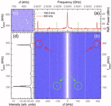
P0兲 共P0/f兲.Figure 2共a兲 shows the power spectra of the signal re-flected by the IDT for two different values of fpiezo at f = 2.924 GHz. Both spectra show a main peak at f and two side bands at a distance fpiezo from the central peak, corre-sponding to the amplitude modulation of the reflected signal. In tapping-mode or noncontact implementations of the present scheme, the amplitude of the side bands should be used as the feedback signal for the AFM controller. Figures 2共b兲 and 2共c兲 plot the spectra of the reflected rf signal as
a function of fpiezo. Side bands are clearly visible at fpiezo共1兲 = 108.5 kHz, fpiezo共2兲 = 300 kHz, fpiezo共3兲 = 560 kHz, and fpiezo共4兲 = 577 kHz. A comparison with the frequencies of the oscillation modes of the cantilever, determined with a con-ventional optical-lever setup 关Fig. 2共d兲兴, confirms that the values of fpiezo共1兲 and fpiezo共2兲 correspond to the first two oscilla-tion modes of the lever. fpiezo共3兲 and fpiezo共4兲 lie outside of the bandwidth of the photodiodes used in the optical-lever setup and correspond to the third mode, probably split due to the cantilever connection to the chip. We note that the intrinsic response time of the system is limited only by the SAW transit time in the IDT region. This yields a high-frequency cutoff in excess of 20 MHz for the chosen geometry, allow-ing very-high-bandwidth dynamic measurements.
Speed of sound is temperature dependent and it is im-portant to estimate how temperature drift can impact the present scheme. To this end we note that in our implementa-tion the maximum of s共f兲 at fmax has a full width at half maximum ⬃3 MHz 共data not shown兲, corresponding to ⬃28 °C 共the temperature coefficient of sound velocity in GaAs is ␣= 35 ppm/ °C 共Ref. 14兲 for SAW propagation in GaAs along the 具110典 direction兲. Temperature control well within this range can be easily achieved in any realistic implementation.
The piezoelectricity of the cantilever substrate material makes it possible also to excite lever oscillations by means of the same IDT used for motion detection. Figure 3共a兲 shows the oscillation amplitude in one of the cantilevers studied as a function of the frequency of the IDT excitation signal. The sharp peak observed at 27 kHz corresponds to the fundamental flexural mode of the cantilever and demon-strates that it is possible to excite mechanical oscillations by FIG. 2. 共Color online兲 共a兲 Spectrum of the signal reflected by the IDT for two mechanical excitation frequency values 共fpiezo兲 corresponding to the
first two cantilever resonances. The IDT excitation frequency was set to
f = 2.924 GHz;共b兲, 共c兲 spectrum of the reflected signal as a function of the
frequency shift⌬f with respect to f and of the piezoexcitation frequency 共fpiezo兲. Four resonances, marked by arrows, can be observed. The vertical
features at⫾100 kHz and ⫾180 kHz are artifacts of the measurement sys-tem;共d兲 cantilever mechanical oscillation modes determined by a conven-tional optical-lever setup.
173505-2 Strambini et al. Appl. Phys. Lett. 96, 173505共2010兲
means of IDTs. Identification of the peak was carried out by measuring the oscillation amplitude as a function of the dither-piezo-excitation frequency关Fig.3共b兲兴 and without ex-citation to detect thermal motion 关Fig.3共c兲兴.
We believe these results can find broad applications for the realization of ultrafast AFM schemes. In particular, we would like to remark that there are very well known schemes to allow measuring wirelessly15 the resonance frequency of an IDT, opening the way to the implementation of wireless rf cantilevers. Based on this, arrays of chemically functional-ized cantilevers that are already employed in gas-sensing systems could be excited and read sequentially by tuning the IDT of each cantilever to a specific frequency. In conclusion, we have presented an all-electrical scheme to excite a canti-lever and detect its motion based on an IDT. Canticanti-lever
de-flection induces a detectable shift in the resonance frequency of the IDT. Owing to the piezoelectricity of the substrate material, the same IDT can be used to excite the mechanical oscillation modes of the lever.
1G. Binnig, C. F. Quate, and C. Gerber,Phys. Rev. Lett. 56, 930共1986兲. 2S. Morita, Roadmap of Scanning Probe Microscopy, 共Springer, Berlin,
2009兲; E. Meyer, H. J. Hug, and R. Bennewitz, Scanning Probe
Micros-copy: The Lab on a Tip共Springer, Berlin, 2003兲.
3C. A. J. Putman, K. O. Vanderwerf, B. G. de Grooth, N. F. Vanhulst, and
J. Greve,Appl. Phys. Lett. 64, 2454共1994兲; P. K. Hansma, J. P. Cleve-land, M. Radmacher, D. A. Walters, P. E. Hillner, M. Bezanilla, M. Fritz, D. Vie, H. G. Hansma, C. B. Prater, J. Massie, L. Fukunaga, J. Gurley, and V. Elings,ibid.64, 1738共1994兲; T. R. Albrecht, P. Grütter, D. Horne, and D. Rugar,J. Appl. Phys. 69, 668共1991兲; F. J. Giessibl,Science 267, 68 共1995兲.
4J. Kokavecz and Á. Mechler,Appl. Phys. Lett. 91, 023113共2007兲. 5S. P. Jarvis, T. P. Weihs, A. Oral, and J. B. Pethica, MRS Symposia
Proceedings No. 308共Materials Research Society, Pittsburgh, 1993兲, p. 127. W. Han, S. M. Lindsay, and T. Jing, Appl. Phys. Lett. 69, 4111 共1996兲.
6M. Penedo, I. Fernández-Martínez, J. L. Costa-Krämer, M. Luna, and F.
Briones,Appl. Phys. Lett. 95, 143505共2009兲.
7J. Brugger, N. Blamf, P. Renaudb, and N. F. de Rooija,Sens. Actuators A
Phys. 43, 339共1994兲.
8N. Umeda, S. Ishizaki, and H. Uwai, J. Vac. Sci. Technol. B 9, 1318
共1991兲.
9G. Meyer and N. M. Am,Appl. Phys. Lett. 53, 1045共1988兲.
10Applied Scanning Probe Methods V: Scanning Probe Microscopy
Tech-niques, edited by B. Bhushan, H. Fuchs, and S. Kawata共Springer, Berlin,
2007兲.
11M. Tortonese, H. Yamada, R. C. Barrett, and C. F. Quate, Transducers’91
International Conference on Solid-State Sensors and Actuators, 24–27 June 1991, pp. 448–451; M. Tortonese, R. C. Barrett, and C. F. Quate, Appl. Phys. Lett. 62, 834共1993兲.
12S. Manalis, S. Minne, and C. Quate,Appl. Phys. Lett. 68, 871共1996兲; T.
Itoh, C. Lee, and T. Suga,ibid. 69, 2036共1996兲.
13G. Y. Chen, T. Thundat, E. A. Wachter, and R. J. Warmack,J. Appl. Phys.
77, 3618 共1995兲; J. Fritz, M. K. Baller, H. P. Lang, H. Rothuizen, P. Vettiger, E. Meyer, H.-J. Güntherodt, Ch. Gerber, and J. K. Gimzewski, Science 288, 316共2000兲.
14C. K. Campbell, Surface Acoustic Wave Devices for Mobile and Wireless
Communications共Academic, USA, 1998兲.
15F. Schmidt and G. Scholl, in Advances in Surface Acoustic Wave
Technol-ogy, Systems and Applications, edited by C. C. W. Ruppel and T. A.
Fjeldly共World Scientific, Singapore, 2000兲, Vol. II, pp. 277–326. FIG. 3.关共a兲 and 共b兲兴 Oscillation amplitude of the cantilever as a function of
the excitation frequency applied to the IDT共a兲, and to the dither piezo 共b兲. 共c兲 Spectrum of the cantilever deflection without external excitation showing the thermal motion. Data were taken with a conventional optical-lever setup.
173505-3 Strambini et al. Appl. Phys. Lett. 96, 173505共2010兲