Autonomous Obstacle Crossing
Strategies for the Hybrid
Legged/Wheeled Robot
CENTAURO
Alessio De Luca
DIBRIS - Department of Computer Science, Bioengineering,
Robotics and System Engineering
University of Genova
In collaboration with: Istituto Italiano di Tecnologia
Supervisors: Prof. Fabio Solari (DIBRIS)
Dott. Nikolaos G. Tsagarakis (IIT)
In partial fulfillment of the requirements for the degree of Robotics Engineering
Acknowledgements
I would like to thank my thesis advisor, Professor Fabio Solari that accepted to follow me on this project. He was always available to possible discussions, taking care of all the steps I achieved, guiding me also in the writing of this final document.
In addition sincere thanks to Nikos Tsagarakis, who offered me this thesis project allowing me to work in his laboratory with all the peo-ple inside it, in particular I would like to thank Luca and Davide, who were so patient to help me and follow my entire work from home and in the laboratory during the experiments, making me improve. I learnt so much from them and this experience.
Last, but not the least, special thanks go to my family and my dear friends who never stopped believing in me and supporting my choices. They encouraged me to follow my dreams and achieve my objectives, giving always the best. Without them, these years would have been much more challenging.
Abstract
The advancement of humanoid robots in the last decades, introduced the possibility to let robots perform tasks originally designed for hu-mans. The applications involve surgery, health care or situations that can be dangerous for a human being like working in half-destroyed areas.
This master thesis deals with the centaur-like robot CENTAURO and was carried out at the Istituto Italiano di Tecnologia, in the Hu-manoids and Human Centered Mechatronics laboratory.
Here we will present the development of the modules used to perceive the environment and to overcome obstacles on the terrain via step-ping on and stepstep-ping over. The ability to use the perception system to perform autonomously a crossing task was novel for the CENTAURO robot.
We will start analyzing the perception which is an important as-pect that a robot needs to have in order to understand which are the elements around it, so that it can navigate avoiding obstacles and interacting with the objects in the scene.
In this project we worked with a 3D LiDAR, a Velodyne Puck, to obtain a representation of the environment as a point cloud. The developed perception module uses the Point Cloud Library (PCL) to process the points representing the scene, since PCL provides state-of-the-art algorithms to perform filtering, segmentation and normal estimation in a point cloud. In particular, vertical and horizontal pla-nar segmentation have been carried out to obtain information about the walls and the floor location. This information is used to navi-gate in the room towards an obstacle and stopping before crashing on it. The knowledge of vertical planes will be used in future to lean of walls while overcoming bigger obstacles maintaining the stability of the robot or to interact with elements on the wall performing manip-ulative tasks.
The second module developed in this project is related to the mo-tion control that allows the robot to overcome the perceived obstacle.
Based on the dimension of the obstacle, assumed with a rectangular shape to simplify the problem, we perform a simple feasibility analysis to understand how it can be crossed: via stepping over or stepping on and down. Following we proceed with the stepping procedure, exe-cuting the methods we implemented that can adapt the length of the step based on the depth and height of the obstacle we are going to cross.
Both modules were tested at the beginning in the simulation environ-ment, Gazebo, then on the real robot CENTAURO in the laboratory, working with obstacles of different size.
Contents
1 Introduction 1
1.1 Problem Formulation . . . 2
1.2 Thesis Outline . . . 2
2 Related Work 4 2.1 DARPA Robotics Challenge . . . 4
2.2 Perception . . . 6
2.2.1 Plane Segmentation . . . 8
2.2.2 Localization . . . 9
2.3 Locomotion and control . . . 10
2.3.1 Wheel Robots . . . 10
2.3.2 Legged Robots . . . 11
2.3.3 Hybrid Robots . . . 12
2.3.4 Control . . . 12
3 CENTAURO 14 3.1 Mechanical and Kinematic Structure . . . 15
3.2 Perception on CENTAURO . . . 16
3.2.1 Velodyne Puck . . . 16
3.3 Software Architecture of CENTAURO . . . 17
3.3.1 XBotCore . . . 17
3.3.2 OpenSoT . . . 19
3.3.2.1 Inverse Kinematic . . . 21
3.3.3 CartesIO . . . 22
3.3.3.1 Stack of Tasks of CENTAURO . . . 23
4 Perception 26 4.1 Point Cloud Library . . . 27
4.2 Filtering . . . 28
4.2.1 Statistical Outlier Removal . . . 28
CONTENTS 4.2.3 PassThrough Filter . . . 30 4.3 Segmentation . . . 30 4.3.1 Model-Based Segmentation . . . 31 4.3.1.1 Algorithm . . . 31 4.3.2 Euclidean Clustering . . . 32
4.3.3 Region Growing Segmentation . . . 33
4.4 Implementation . . . 34 4.4.1 Octomap . . . 35 4.4.2 Base Filtering . . . 36 4.4.3 Planar Segmentation . . . 38 4.4.4 Gap Identification . . . 42 4.4.5 Obstacle Detection . . . 42
5 Motion Control for Gap and Obstacle Crossing 45 5.1 Quasi-static assumption . . . 45
5.2 Balance Control . . . 45
5.3 Implementation . . . 47
5.3.1 Joint Space control for arms . . . 47
5.3.1.1 Polynomial Interpolation . . . 50 5.3.2 Feasibility Analysis . . . 51 5.3.3 Crossing procedure . . . 54 5.3.4 Force Estimator . . . 57 6 Results 58 6.1 Perception results . . . 58 6.1.1 Simulation . . . 58 6.1.2 Real Case . . . 61 6.2 Crossing results . . . 68 6.2.1 Simulation . . . 68 6.2.2 Real Case . . . 72
List of Figures
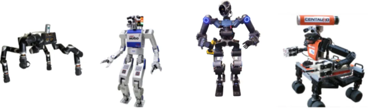
2.1 DRC robots: RoboSimian(1), DRC-HUBO(2), WALK-MAN(3)
and Momaro(4). . . 5
3.1 Centauro robot (the image was taken by Arturo Laurenzi - IIT). . 15
3.2 Kinematic Layout of the CENTAURO robot (Image from (47)). . 16
3.3 Time of flight process (en.wikipedia.org). . . 17
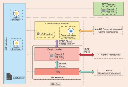
3.4 XBotCore main elements (image from (48)). . . 18
3.5 Hierarchical Paradigm of OpenSoT (image from (50)). . . 21
4.1 Example of a point cloud (image from pcl.readthedocs.io). . . 27
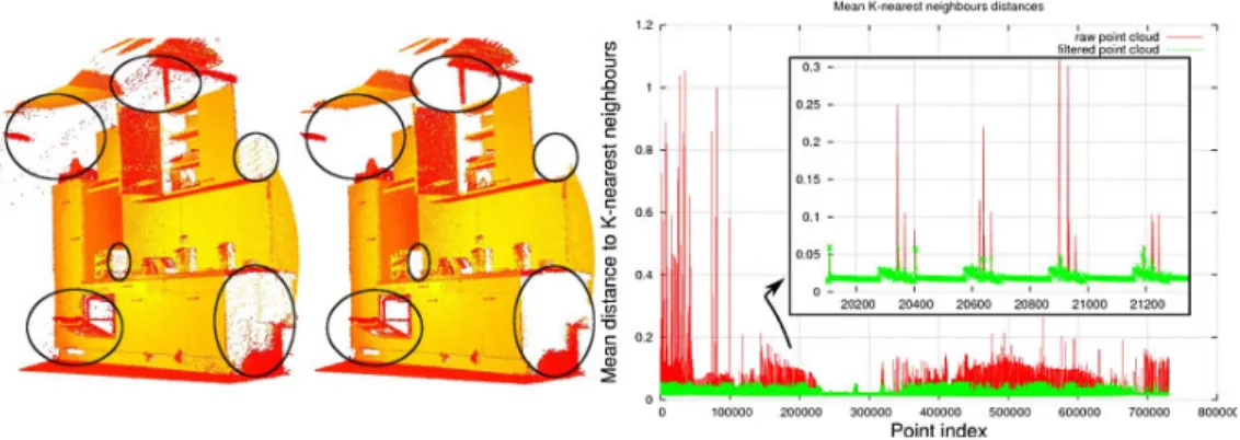
4.2 Example of Statistical Outlier Removal (image from pcl.readthedocs.io). On the left we have the original dataset, while on the right the one where the outliers were trimmed. The graph, instead, shows the mean k-nearest neighbor distances in the neighborhood of a point, before (red) and after (green) the application of the filter. . . 29
4.3 VoxelGrid Downsampling of a point cloud with different resolutions. 30 4.4 Example of Euclidean Clustering where each color represent a dif-ferent cluster obtained. . . 33
4.5 Pipeline of the perception processing developed. . . 35
4.6 Example of the point cloud resulting from the use of octomap. . . 36
4.7 Example of the output of the base filtering node. Showing the 3x3 area around the robot in a real application. . . 37
4.8 Point cloud limited to the corridor in front of the robot. . . 39
4.9 Segmentation pipeline . . . 39
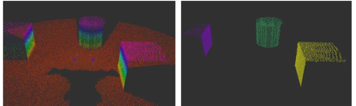
4.10 Outputs of the pipeline’s blocks. Starting from the left we have: Octomap representing the entire scene, 3x3 area around the robot, normal estimation and the segmented horizontal plane in front of the robot. . . 40
4.11 Segmentation method comparison. . . 41
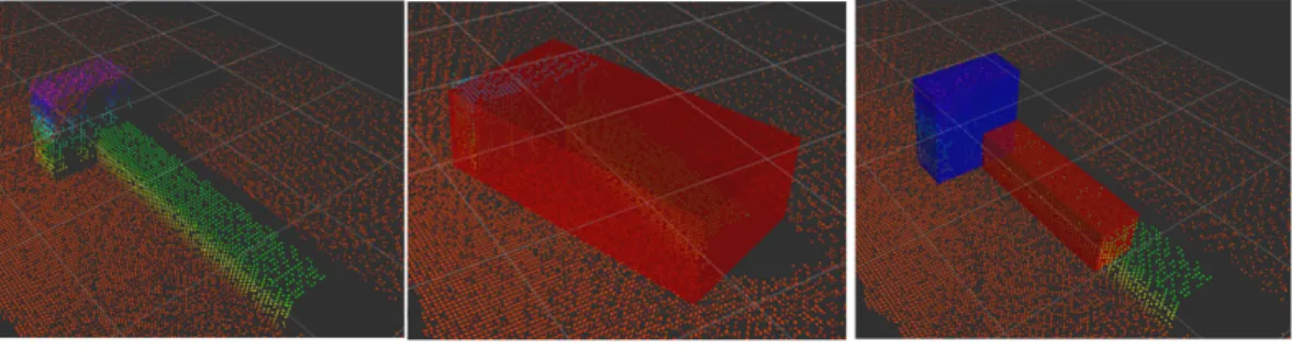
4.12 Results of obstacle estimation with and without the euclidean clus-tering . . . 43
LIST OF FIGURES
4.13 Bounding box of an obstacle segmented in front of the robot. . . . 44
5.1 Flowchart showing the steps and decisions that need to be taken to adapt the step to the obstacle. . . 48
5.2 Difference between ”Homing” and our custom pose for obstacle crossing. . . 49
5.3 Difference of Center of Mass (CoM) and pelvis in Homing and custom configuration of the arms. . . 50
5.4 Simplified feasibility analysis for stepping over. . . 53
5.5 Improvements obtained moving the wheel before stepping. . . 55
5.6 Explanation of the cases 3a and 3b for stepping on procedure. . . 56
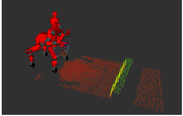
6.1 Starting configuration used for the simulation of the gap recogni-tion task. . . 59
6.2 Configuration of the environment in the real world. . . 62
6.3 Difference between the map before and after the driving motion. This was taken from the simulation environment to make the prob-lem easier to be seen. . . 65
6.4 Mean and standard deviation of the measurements obtained with the real robot with three different approaches. . . 66
6.5 Comparison of the point clouds in simulation (left) and real world (right). . . 67
6.6 Obstacle crossed via stepping over in simulation, compared to the feasibility analysis. . . 69
6.7 CoMstability in stepping over procedure. . . 70
6.8 Sequence of images showing the steps performed to cross an ob-stacle via stepping over. . . 71
6.9 CoM stability in stepping over procedure moving also along the y axis. . . 72
6.10 Images showing the obstacle crossed in the real world via stepping on. . . 74
6.11 Force estimation during the stepping over procedure in the real case. This graph shows unwanted oscillations in the estimates during the movement. . . 75
List of Tables
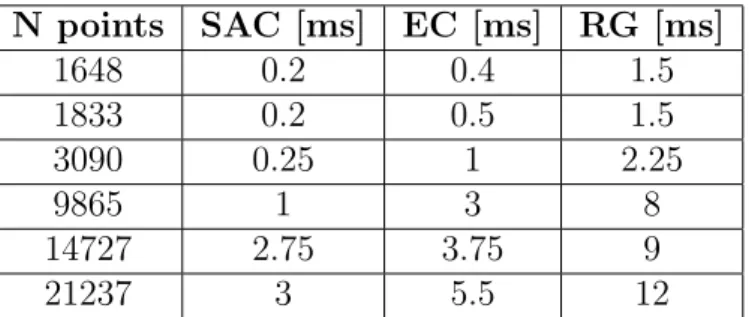
4.1 Time used to perform segmentation of a point cloud using Model-based (SAC), Euclidean Clustering+Model-Model-based (EC) and Region Growing (RG). Results have been obtained on my laptop
(specifi-cations in Chapter6). . . 42
6.1 Estimates of a gap between two platforms in Gazebo. . . 60
6.2 Estimates obstacle via Oriented Bounding Box (OBB) in Gazebo. 60 6.3 Estimates obstacle via OBB in Gazebo with Statistical Outlier Removal (SOR) . . . 61
6.4 Tests showing the differences between the distances measured on the real world and the ones obtained in the simulated environment. 62 6.5 Distance between the front wheels and the gap/obstacle in the real case before and after moving the robot. . . 63
6.6 Distance to the obstacle updating the map while the robot was moving. . . 64
6.7 Results obtained with a static map and 0.03 as resolution. . . 65
6.8 Estimates obstacle via OBBin real world (no SOR). . . 67
6.9 Estimates obstacle via OBBin real world (with SOR). . . 67
6.10 Measurements between front wheels and the obstacle, before and after driving. . . 73
Glossary
APHT Adaptive Probabilistic Hough Transform. 8
API Application Programming Interface. 17, 19,23
CoM Center of Mass. vii, 21,24, 46, 47,50, 53–55, 57,68–72, 74,76
DARPA Defense Advanced Research Projects Agency. 4
DoF Degree of Freedom. 1,5, 15, 16,19, 24
DRC DARPA Robotics Challenge. vi, 4–6, 19
eHQP equality Hierarchical QP. 20
EKF Extended Kalman Filter. 10
EPFL ´Ecole Polytechnique F´ed´erale de Lausanne. 10
EtherCAT Ethernet Control Automation Technology. 17
EU European Union. 14
GPS Global Positioning System. 10,77
HAL Hardware Abstraction Layer. 18
HCOD Hierarchical Complete Orthogonal Decomposition. 20
hHQP inequality Hierarchical QP. 20
HT Hough Transform. 8
IEEE Institute of Electrical and Electronics Engineers. 17
Glossary
IK Inverse Kinematic. 21, 22
IR Infrared. 7
LiDAR Light Detection and Ranging or Laser Imaging Detection and Ranging.
2, 7,16, 17, 76
MoT Math of Tasks. 20, 24
NASA National Aeronautics and Space Administration. 11
OBB Oriented Bounding Box. viii, 43, 60,61, 67
OROCOS Open Robot Control Software. 19
PCA Principal Component Analysis. 40
PCL Point Cloud Library. 2,9, 27, 28,30, 31, 39,43, 60, 76
PHT Probabilistic Hough Transform. 8
QP Quadratic Programming. 13, 20, 22, 23
RANSAC Random Sample Consensus. 8, 31
RHT Randomized Hough Transform. 8
ROS Robot Operating System. 19, 23,35, 37, 38, 42,44, 59
RT Real-Time. 17–19
SDK Software Development Kit. 7
SEA Series-Elastic Actuator. 15
SLAM Simultaneous Localization and Mapping. 9, 10
SOR Statistical Outlier Removal. viii, 61, 66, 67
SoT Stack of Tasks. 23
SRDF Semantic Robot Description Format. 23
Glossary
URDF Unified Robot Description Format. 23
USB Universal Serial Bus. 7
VF Virtual Frame. 24
XDDP Cross Domain Datagram Protocol. 19
Chapter 1
Introduction
In the last decades there was an increasing trend in building robots for disaster scenarios like earthquakes, nuclear accidents and tsunami. This need comes from the fact that these situations are not safe for a human. In fact, the aforemen-tioned scenarios can put at the risk the health of a person with the presence of radiations, toxic gases or the possibility of the ceiling and walls to fall down. In order to avoid to damage the humans working under these conditions, we need a really high level of attention and planning before entering in a risky area. Un-fortunately this does not completely eliminate the risks for the operators.
For these reasons researchers started to design and develop robots with the abil-ity of carrying out tasks autonomously or semi-autonomously, keeping the human operator safe.
A robot, in order to substitute a human being, has to be able to perform a variety of tasks interacting with the elements of the environment, avoiding ob-stacles and making a way to the final goal assigned.
Generally what we need is a mobile robot (wheeled, legged or hybrid) that is built to move across the environment identifying possible obstacles and dangers thanks to a sensory system made of different cameras; in addition, if we want to interact with some objects, we need at least one arm ending in a gripper or a more complex hand. Based on the Degree of Freedoms (DoFs) of the arms and the complexity of the hand, the robot can be able to accomplish tasks like: climbing stairs, collecting objects or opening doors and valves.
A mobile robot designed with this goal in mind, can be achieved by merging the main elements of robotics: perception, planning and control.
The perception system is essential to perceive the environment and the elements we need to work with, in such a way that the robot can localize itself in a map and recognize the elements that may be used to achieve some tasks. Planning, instead, allows the robot to find the best trajectory to follow in order to reach
1.1 Problem Formulation
the desired pose in the space, reducing the energy and time needed. Finally, the control is the element that is needed to be able to move the robot as we want, controlling the single joints or the end effectors to a specified configuration.
In this thesis project we worked with the centaur-like robot CENTAURO that was originally used to perform tasks while being teleoperated by a human. In the last years the team started to work on additional features that allows the operator to be more free, by adding semi-autonomous tasks to the CENTAURO with the objective to obtain in the end a fully autonomous robot. More informa-tion about the CENTAURO will be given in chapter 3 where we will analyze, in more details, its design, software and control architecture.
1.1
Problem Formulation
The purpose of this thesis project was to increase the autonomous capabilities of the CENTAURO robot by making use of its perception system to take decisions. In fact, the sensors to perceive the environment were generally used to show the surrounding area to the operator from a robot point of view and not by the robot itself to perform tasks autonomously.
The first part of this project was focused on the use of the Point Cloud Library (PCL) to process the point cloud data representing the environment, acquired by the 3D LiDARmounted on the head of the robot.
At the beginning the point cloud was filtered in order to reduce the noise and its size, then we compared some segmentation techniques and we applied a planar segmentation to extract horizontal and vertical planes. These planes can be used to touch a wall or identify gaps in the terrain. In addition we processed the cloud in order to extract the obstacles in front of the robot, assuming to deal with rectangular obstacles for simplicity.
The second part of the project was related to the actual crossing of the obstacle. Firstly we performed a simple feasibility analysis to check how the obstacle can be crossed by the robot, then we developed some methods to perform stepping over, on and down. These procedures are used to overcome different obstacles, adapting the length of the steps to the dimension of the obstacle we are facing.
1.2
Thesis Outline
This master thesis is organized as follows: in Chapter 2 we will review some re-lated works in mobile and humanoid robots focusing in perception aspects and
1.2 Thesis Outline
locomotion design. Then in Chapter 3 we will explain in more details the CEN-TAURO robot from an hardware and software point of view introducing the framework used to control the robot.
Chapters 4 and 5 will explain what was performed in this project in terms of perception and motion control for the obstacle crossing task, while in Chapter 6
we will see the results obtained in simulation and on the real robot. Finally we will draw conclusions and talk about the future works in Chapter 7.
Chapter 2
Related Work
The robotics community in the last years spent a lot of effort on the development of mobile and humanoid robots capable of performing tasks autonomously. The possible application of these robots is different since they can be used in several fields like industrial, health care and rescuing. In particular we will focus on the last one that needs robots capable of navigating in cluttered environments, understanding what is around them to be able to interact with different kind of objects.
2.1
DARPA Robotics Challenge
Considering that the development of robots used for exploration of unknown and destroyed areas is an important topic, especially after the Fukushima nuclear power plant disaster of 2011, the Department of Defense of the United States in-troduced the DARPA Robotics Challenge (DRC), where DARPAis an acronym for Defense Advanced Research Projects Agency, an agency responsible for the development of novel technologies for the military division.
The DARPA competition was introduced with the main goal of promoting the innovation in human-supervised robotic technology for disaster-response opera-tions.
It was focused on the development of a human-supervised ground robot with the capability of executing complex tasks in dangerous, degraded and human-engineered environments. The competitors of this challenge developed robots with the capability of utilizing standard tools and equipment commonly available in human environments, ranging from hand tools (i.e. a drill) to vehicles that need to be driven to a target place.
Achieving its goal, the DRCadvanced the state-of-the-art of different areas like: mobility, supervised autonomy, platform dexterity and endurance. In particular,
2.1 DARPA Robotics Challenge
the improvements in supervised autonomy allowed better control of robots by non-expert supervisors and enabled effective operation despite degraded commu-nications due to intermittent connection, low bandwidth and high latency. Some examples of robots developed for this competition can be seen in the fol-lowing figure.
Figure 2.1: DRC robots: RoboSimian(1), DRC-HUBO(2), WALK-MAN(3) and Momaro(4).
Starting from the left, we have:
• RoboSimian (1) is a statically stable quadrupedal robot with four 7 DoFs
limbs, ending in hands. It can switch between driving and stepping loco-motion but the robot needs to reach a predefined sitting pose to do this;
• DRC-HUBO (2) is a humanoid robot with 32 DoFs that wins the DRC
in 2015. It moves with a bipedal walking but it is also able to lower to a kneeing pose and perform driving locomotion if the terrain is sufficiently flat;
• WALK-MAN (3) is a humanoid robot developed in 2015 by the Italian Insti-tute of Technology. It has 33 DoFs and mounts custom made series-elastic actuators to give robustness and natural adaptability during interactions with the environmental elements;
• Momaro (4) is a centaur-like robot that, unlike the RoboSimian, is able to switch between driving and stepping without the need to reach a specific configuration. The centaur shape was chosen to reduce balancing issues during locomotion and manipulation tasks.
2.2 Perception
The CENTAURO robot takes inspiration from the kinematic design of the Mo-maro and the actuation system developed for the WALK-MAN.
We have seen few examples of robots built specifically for the DRC. Now, in order to be able to work in unknown and unfriendly areas, we have to face prob-lems regarding vision and locomotion. In the following sections we will analyze the past literature regarding these aspects.
2.2
Perception
Over the past 40 years, researchers in the field of computer graphics, computer vision and machine learning, developed multiple solutions for solving the 3D re-construction problem. This kind of problem is important for the autonomous navigation of robots which have to move across unknown environments, in such a way that they can be able to understand how to move, avoiding dangerous areas and obstacles.
Starting from the 80s, researchers studied how to identify the environment (or a part of it like a road) and reconstruct objects in 3D from images. The first algorithms implemented to achieve these tasks were the ones based on color seg-mentation (5). With this technique, a camera is used to acquire images from which they extracted the element of interest easily by looking only at the color, pixel by pixel. If the color of a pixel was in a specified range, that pixel would be count as part of the object. Of course this naive solution has limitations. In fact we cannot use this algorithm to find every element in the scene, especially if we have more objects of the same color close one with respect to the other. Following, Zhang and his team developed methods based on the epipolar geom-etry in a stereo system (6) where, thanks to the estimation of the epipolar, they were able to compute the 3D reconstruction of a face via triangulation. A draw-back of this method is the calibration which is needed to carry out the task. For this reason the user, at the beginning of each experiment, needed to calibrate the camera system using a well-known pattern, generally a chessboard, to be able to estimate the camera parameters. However, Zhang’s experiments showed that their calibration was not so valid for reconstructing other elements of the space. In the same period, Huber et al. used another approach, they implemented the surface matching algorithm (7) to reconstruct an internal environment. This algorithm showed successfully object recognition and three dimensional object modeling properties (8). This method was more powerful with respect to the previous ones, because it did not need feature extraction or a priori knowledge; so, since it was faster, it could be used in larger scale models. Due to the
decreas-2.2 Perception
ing of the computational resources based on the simplifications achieved, these methods were used in different studies.
Later, in November 2010, with the release of the Microsoft Kinect, there was a significant change in the computer graphics and robotics.
The Microsoft Kinect consists of an RGB camera, depth sensor and multi-array microphone. In addition, the Kinect has an Infrared (IR) transmitter and a re-ceiver placed in such a way that there is a small angle between them. The infrared information are used to compute the depth using the triangulation method. Few months later, in 2011, the software developer H`ector Martin, implemented an open source Software Development Kit (SDK) for the Kinect device (22). In this way, he permits the transmission of both depth and RGB or raw infrared images, using the USB only. From now on, the Kinect was largely used in 3D reconstruction and tracking, not only in the video game field. Thanks also to its low price, several robots has a Kinect mounted that allows them to obtain 3D information of the areas in which they have to operate.
An alternative to the Kinect are the laser scanners which are sensors that allow to obtain a representation of the environment using measurements of the distance between the sensor and the objects around it. Laser scanner technique works evaluating the time used for the light to bounce on the object and go back to the sensor.
Despite the fact that a great number of applications involve the Kinect, it has been proved by Zug et al. (9) that laser scanners are more suitable for robotic applications since they allow to acquire knowledge of all the surrounding area.
Using the 3D data obtained from the RGB, RGB-D sensors or 3D LiDARs, re-searchers were able to reconstruct the environment that may be segmented into different ground regions. These segments allow a robot to have information about the elements of the environment and, using planning algorithms, it may under-stand where it is the most safe area to navigate through using some cost functions (21).
This technology was used in several robotic applications, also in mobile ground robots that have to operate in cluttered and degraded environments. Thanks to the aforementioned devices, robots are able to scan the environment and recon-struct it, based on the distances measured, extracting semantic information from a point cloud.
2.2 Perception
2.2.1
Plane Segmentation
The process of segmenting a point cloud to extract some relevant elements was studied and applied in many applications. Here we will mainly focus on the ex-traction of planes from a point cloud that can be achieved using different meth-ods.
The most popular techniques are: Hough transform, model based and region growing methods.
Hough Transform
The Hough Transform (HT) (10) can be considered as a feature-detection tech-nique in which every point of the input votes for a possible plane. All the votes are accumulated into the so called accumulator and the element that obtained the highest score is selected as the output of the algorithm.
In the case of plane segmentation the accumulator is a 3D matrix representing the three different parameters used to identify a plane in the space.
The Hough Transform was firstly introduced for the detection of lines in 2D images by Paul Hough (10). Later different variants have been proposed like the Probabilistic Hough Transform (PHT) (11) which tries to reduce the com-putational time needed by using a random subset of the input to compute the accumulator. The randomness of this technique makes thePHTnot deterministic and an optimal tuning of the parameters is needed to obtain good results. This was not easy to achieve, so the Adaptive Probabilistic Hough Transform (APHT)
was introduced (12). Here the accumulator is monitored during all the voting process until the result becomes stable.
In the same period Xu et al. (13) introduced theRandomized Hough Transform (RHT) which uses the knowledge that a plane is defined by three non-collinear points. In fact, the RHT builds the accumulator in such a way that each vote is cast by a group of three non-collinear points randomly selected. This technique is the fastest one, between the Hough Transforms, but it does not scale with the size of the point cloud.
Model-Based Segmentation
Shape detection can be also performed using the Random Sample Consensus (RANSAC) which, similarly to the RHT, selects randomly three non-collinear points finding the plane that best approximates the input set. In 2007 Schnabel et al (14) optimized the RANSAC method introducing an octree representation to evaluate the distances between the elements of the input. This reduces the time needed for the algorithm to be executed.
2.2 Perception
Region Growing
Region growing methods (15) are clustering techniques that uses the information about the distance with respect to the neighbours, expanding regions (segments) based on local characteristics like the curvature.
Other methods
In addition to the aforementioned state-of-the-art approaches, the researchers de-veloped new methods for segmenting a point cloud.
In 2004 Besl et al. (16) developed an algorithm based on the scan line grouping (17) in which an adaptive line fitting method was developed, applying then the region growing to use the statistics obtained from the lines. This was applied for segmenting the horizontal planes of the stairs for a humanoid climbing.
Later, in 2014, Hulik et al. (20) improved the standard Hough Transform in terms of time and memory requirements using the localization of the robot to define the accumulator based on the points transformed from the world coordinates to the Hough space.
In the same period, for the Darpa Robotics Challenge, Palnick (18) performed a plane segmentation using model-based methods provided by PCL(19), combin-ing filters to reduce the noise, obtaincombin-ing more accurate results.
The Hough Transform proved to be a reliable method to extract different kind of shapes from a 2D image or a point cloud. Of course it is a more complex technique compared to others. For this reason, since our goal was to work with simple models, we preferred to use the state-of-the-art algorithms provided by the PCL library involving the model-based segmentation; by the way, a more detailed description will be given in Chapter 4.
2.2.2
Localization
In addition to the segmentation and the reconstruction, an important problem with mobile robots in unknown environments was the localization. Without the localization, a robot would not have the ability to move autonomously in an area, without having a priori knowledge.
The problem of designing a map and localize the robot inside it came out in the 1980s-1990s. One solution to this problem was the Simultaneous Localization and Mapping (SLAM). Researchers showed that was possible for an autonomous vehicle to start in an unknown location of an unknown environment and, using relative observations only, incrementally build a perfect map of the world and compute, simultaneously, a bounded estimate of the vehicle location (23). The main advantage of the SLAM was that it eliminates the need for a priori
2.3 Locomotion and control
topological knowledge of the environment, allowing to be used in any kind of territory.
The most popular philosophy adopted is the Extended Kalman Filter (EKF)
based approach, because this filter provides recursive solution in navigation prob-lem and the possibility to compute estimates for uncertainty in the vehicle motion and map landmark observations.
The two aforementioned problems, the SLAM and the 3D reconstruction, where also put together, of course, by using the RGB-D cameras to infer the informa-tion needed to apply the 3D reconstrucinforma-tion of the terrain and solve the SLAM
problem, localizing the robot into the defined map. This procedure has been also tested offline using datasets, synthetically generated as in (25).
An example of their use comes from Weingarten and Siegwart of theEPFL. They used anEKF-basedSLAMalgorithm to achieve: 3D reconstruction, mapping and localization (24). They showed that this approach leads to a compact map rep-resentation which can be used effectively for the robot localization.
Unfortunately the localization module is currently not equipped on the CEN-TAURO robot. The team is working on integrating a GPS device to track the robot’s movement in order to correct the position of the robot while it is moving in an unknown environment.
2.3
Locomotion and control
Once that we have analyzed the perception systems, we can move to the locomo-tion and control aspects.
A mobile robot, in order to navigate in the environment, has to be equipped with a locomotion system that depends on the application of the robot (extraterres-trial exploration, underwater, aerial and so on) but also on technical criteria like controllability, maneuverability, stability and energy consumption.
Considering land-based applications, a mobile robot can be classified as wheeled, legged, tracked or hybrid (here we will not consider tracked robots because they are not relevant for our goal), based on the locomotion system implemented. In the following we will briefly investigate the main advantages and problems of these types of robot.
2.3.1
Wheel Robots
Wheels are one of the most used locomotion system; few examples are Mars rovers like Opportunity and Spirit (26) or simply robots used in several houses like the Roomba (27).
2.3 Locomotion and control
Wheeled robots can be an interested choice because wheels are easier to use with respect to articulated legs. They need a simpler design and controller since the robot will move in flat terrain. Another important aspect to consider is that they generally have less problems in terms of balance. This is due to the fact that all the wheels are supposed to be always in contact with the ground.
When dealing with wheeled robots, there is an essential element that we have to keep into account, the number and the types of wheels used in the robot to model the kinematics and dynamics (28).
In fact, there are different kind of wheels that can be chosen (29): fixed, steer-able, castor or swedish (Mecanum). The first three are said to be conventional since the velocity of the contact point is equal to zero, while in the swedish wheel only one component of the velocity of the contact point is zero, the one along the motion (30).
Based on these choices a robot can be defined as omnidirectional robot.
Usually, for stability reasons, a wheeled robot has at least three wheels to be able to maintain its balance without much effort (31).
Wheeled robots are easier to work with but they have some limits. In more details, wheeled robots are limited to navigate in flat terrains since they have difficulties moving on irregular floors and crossing obstacles. For this reason the research community started to move on also other types of mobile robots.
2.3.2
Legged Robots
In order to overcome the problems of wheeled robots, a change in the locomotion system was needed, substituting the wheels with articulated legs. In particular, even if they are usually more expensive, legged robots have the ability to per-form steps, allowing them to move in flat terrains but also on irregular ones and crossing obstacles.
The most studied legged robots are the humanoid ones, since they can also be used to analyze the walking patterns for prosthesis or other medical purposes. Despite the increasing navigation capabilities, legged robots suffers from stability issues. In fact, balancing a legged robot during movements is a tough challenge. Several humanoids have been developed in the last decades, few examples are the Atlas from Boston Dynamic (32), NASA’s Valkyrie (33) and Asimo (34). Some research teams had been able to perform complex locomotion tasks such as climb-ing, running and jumping with humanoid robots as in (35) and (36), showing that mobile robots have the potential to complete elaborated tasks for exploration or rescuing applications.
2.3 Locomotion and control
As we said, biped robots may have balance difficulties. For this reason, an-other kind of legged robots that were studied are the quadrupeds. Their design includes four legs instead of two, allowing to increase the stability, being able to lift one or two feet leaving the possibility to keep the balance of the overall robot. In addition, they can remain statically stable when they are idle but, they need dynamic walking control, commanding also the Center of Gravity during the gait. Examples are the HyQ (37) from Claudio Semini et al. and the Boston Dynamic’s Spot (38) that were used also to pull heavy objects like planes or cars.
2.3.3
Hybrid Robots
So we have seen different kind of mobile robots that have their advantages but also some drawbacks. In order to merge the benefits of both legged and wheeled robots, researchers studied and designed hybrid robots with a structure defined generally has legs ending in wheels. In this way the robots are able to perform driving, moving in a flat environment, having more stability and lower energy consumption but, when needed, they can use the legs to perform stepping and cross obstacles or damaged terrains.
Based on their kinematic design they can have to reach a specific configuration to change between driving and stepping, as for the RoboSimian.
An example of hybrid robot designed to accomplish tasks in unknown and de-graded environments is the CENTAURO.
2.3.4
Control
When we have defined the kind of robot we want to use, we have to implement a controller in order to perform specific locomotion and, eventually, manipulation tasks. Once that the environmental information have been acquired from the perception system, the robot needs to understand how to move and consequently controls the actuators.
Since complex robots present nonlinear dynamics, nonlinear control techniques are needed, which use the system’s knowledge and the eventual parameters to reproduce the desired behaviour. The objective of the control is to allow the robot to reach the desired pose while maintaining the stability of the system. There are different control strategies that allow to control a robot, for example we have the linearization-based control which approximates the nonlinearities of the system with something linear, to simplify the problem and so the calculation. Another possibility is the application of the Lyapunov theory-based control (39) which is based on the minimization of a Lyapunov function to assure asymptotic stability of the control loop.
2.3 Locomotion and control
The CENTAURO robot, the one used in this thesis project, is controlled through the use of a Cartesian Impedance Controller, which is used to relate the wrench exchanged with the environment by the robot to the cartesian pose and the ve-locity errors.
The Impedance Control was firstly introduced by Hogan (40) as an efficient oper-ational space controller with the ability to robustly handle the contacts with the environment. It is useful because it does not need the inversion of the kinematics but only the computation of the forward kinematics and it requires joint level torque control. In (41) Ott et al. extended the Cartesian Impedance Control to be used also with redundant robots introducing the Null Space Stiffness as a sec-ondary task to use the joint level stiffness inside the controller with two priorities. Following the work proposed in (42) shows a two level Cartesian Impedance con-troller where the task at lowest priority does not influence the primary task, using in the minimization process a weighted squared magnitude of the acceleration er-ror. Then the inverse dynamics problem was solved as shown in (43) by defining a hierarchical Quadratic Programming (QP) problem where accelerations, torques and contact forces were computed together.
Finally we arrived in (44) which shows the controller used by the CENTAURO which is an extension of the previous formulation, where it was added the possi-bility to handle contacts and motion together.
Chapter 3
CENTAURO
In this chapter we will introduce the robot CENTAURO which is the one used in this project.
The CENTAURO robot comes from the CENTAURO Horizon 2020 EU project (45), where the Horizon is the biggest EU Research and Innovation programme. The project was funded for more than 4 million euros due to its great importance and impact in the teleoperation of complex robot with the final goal to perform human-designed tasks also remotely in degraded areas, being able to complete inspections and rescuing tasks.
The robot CENTAURO combines the Momaro’s kinematic design with the com-pliant actuation concept of the humanoid IIT’s Walk-Man. In fact, we still have the centaur-like shape with four articulated legs and an anthropomorphic upper body.
The choice of the centaur shape has two main advantages: having four legs, instead of two, allows the robot to have more stability, also while performing precise manipulation tasks, while the anthropomorphic upper body was chosen to be similar to a human one, so that it can be teleoperated in a more intuitive way having, at the same time, a good reachable space for the end effectors.
3.1 Mechanical and Kinematic Structure
Figure 3.1: Centauro robot (the image was taken by Arturo Laurenzi - IIT).
3.1
Mechanical and Kinematic Structure
From a mechanical point-of-view, CENTAURO is driven by custom-made torque-controlled Series-Elastic Actuators (SEAs) (46), which can offer a compliant be-haviour that can adapt to the situation, increasing the tolerance to impact loads. The lower-body is made by four 5 DoFs legs ending in a 360o steerable wheel.
This leg design was taken from the Momaro robot and combines the benefits of omnidirectional driving and stepping locomotion. In this way, if the terrain is sufficiently flat, the robot can drive across it, which results in a higher velocity and lower energy consumption. While, for more difficult areas, the robot can navigate overcoming obstacles by stepping. The CENTAURO, as the Momaro, is able to switch between driving and stepping without the need of reaching a predefined pose. This allows the robot to change the motion even under load.
The upper-body was designed in order to be similar to a human one. For this reason CENTAURO was built with two 7 DoFs arms ending in two hands. The degree of redundancy in the arm helps the robot to overcome possible constraints that may be introduced by obstacles in the environment.
3.2 Perception on CENTAURO
Figure 3.2: Kinematic Layout of the CENTAURO robot (Image from (47)).
Overall, the robot CENTAURO has 42DoFs(plus the hands) and weights 92 kg. The height of the robot can change in the range from 112 cm to 171 cm, based on the extension of the legs.
3.2
Perception on CENTAURO
The perception of the environment on the CENTAURO robot is achieved using a variety of sensors that can provide different kind of information from different points of view. In fact CENTAURO is equipped with a Velodyne Puck 16 sensor, which is a continuously 3D rotating laser scanner that provides range measure-ments. Moreover, three wide-angle RGB cameras are used to capture images from the robot head, and an additional RGB-D sensor, a Kinect V2, is mounted below the other cameras.
For this thesis project the team chose to use only the Velodyne sensor to collect the environment representation as a point cloud but in the future we may merge the information collected by all these sensors.
3.2.1
Velodyne Puck
As mentioned before, the CENTAURO robot is equipped with a 3D LiDAR sen-sor, mounted on the head.
LiDAR, which stands forLight Detection and Ranging or Laser Imaging Detection and Ranging, is a technique used to determine the distances of the surrounding obstacles and environment’s elements. It is based on the time-of-flight principle, so there is a light pulse which is transmitted and it is measured how long it takes
3.3 Software Architecture of CENTAURO
to bounce back (Fig. 3.3); in this way it is possible to estimate the distance of the object in the space by looking at the time used for the pulse to come back to the source. This technology is accurate but not perfect of course, since factors like reflexive index and smoothness of the surface of the object may affect the resulting measurements.
By the way, LiDARs are widely used in robotics because of their accuracy and velocity, in fact time-of-flight sensors operate more quickly compared to other laser methods, providing up to 160 operations per second.
In particular the Velodyne Puck has 16 channels, a resolution of 3 centimeters and can find up to 300’000 points per second.
Figure 3.3: Time of flight process (en.wikipedia.org).
3.3
Software Architecture of CENTAURO
Now we will focus on the software architecture implemented in the CENTAURO robot that can be seen as three main elements: XBotCore (48), OpenSoT (50) (51) and CartesIO (52).
3.3.1
XBotCore
XBotCore (Cross-Bot-Core) is an open-source, light-weight,Real-Time (RT) soft-ware platform for robotics system that was designed to be both a RT robot con-trol framework and a software middleware. It provides a simple and easy-to-use middleware Application Programming Interface (API) for both RT and non-RT
control frameworks. This API is completely flexible with respect to the frame-work a user wants to utilize.
XBotCore is a software platform forEtherCAT-based robots, whereEthernet Con-trol Automation Technology (EtherCAT)is an industrial communication protocol that enriches the standard IEEE802.3 Ethernet, allowing to transfer files with a
3.3 Software Architecture of CENTAURO
precise synchronization between the master and the slaves.
The design goals of this software platform lied at the foundations of a complex system, a robotic one, and are the most crucial phase in the software development process. The team wanted something designed to be a RT control system, easy to use, flexible and that can also work with non-RT tasks.
Figure 3.4: XBotCore main elements (image from (48)).
The team ended up with a framework which consists of different components, where each one contributes to achieve one or more of the desired goals.
• Robotic HAL: the Hardware Abstraction Layer (HAL) allows to achieve a cross-robot compatibility enabling the use of the same control software modules with different robots. The idea was to introduce an independent layer to integrate new components like actuators or sensors;
• Plug-in Handler : This module relies on theRTcontrol and the possibility to expand the software structure. In order to do this, the plug-in handler was designed using a single RT thread running at high frequency (i.e. 1 KHz) for loading and executing a set of plug-ins, acquired from the configuration file. If there is the need to run non-RTplug-ins, we have the NRTDeployer, which mimics the behaviour of the plug-in handler in the non-RT layer;
3.3 Software Architecture of CENTAURO
• Communication Handler : it is a set of non-RT threads that allow the com-munication with external modules. The data are exchanged between the threads using shared-memory (using lock-free synchronization patterns on the RT threads) or through Xenomai-specific datagram protocols, Cross Domain Datagram Protocol (XDDP), having asynchronous communication between RT and non-RT threads, without the need of mode switches (in-voluntary changes of a RT thread to secondary mode caused by a non-RT
system call);
• XBotInterface: a set of flexible interfaces that enables the framework to be able to work with state-of-the-art, robot control frameworks like ROS,
YARP, and OROCOS. The team developed an API to be used to com-municate with the robot sending commands and sensing its state from
ROS nodes, OROCOS components or XBot RT plug-in in a uniform way. With this in mind, they designed a XBotInterface library. So, with the objects of the XBotInterface class, we are able to collect measurements from the robot sensors and control references. In addition, other classes have been defined, such as XBot::Joint as the most atomic component and XBot:KinematicChain as a set of joints belonging to a chain. Furthermore, to make the development of control algorithms easier, the team provided also a full-robot interface based on the Eigen3 linear algebra library.
Moreover, since robotics applications may require high frequency control loops, XBotCore can satisfy hard real time requirements (predictable timing constraints), while ensuring 1 KHz control loop even if used in a Multi-Degree-Of-Freedom sys-tem.
It was tested and validated performing experiments on the WALK-MAN robot (33 DoFs) inspired by the DRCtasks, where the Whole-body control and inverse kinematics were solved through the OpenSoT control framework, COMAN+ (49) and the CENTAURO.
3.3.2
OpenSoT
OpenSoT is an open-source software library, developed by the Italian Institute of Technology, that can be used to solve robotics control problems. It includes high-level interfaces to the state-of-the-art algorithms used for kinematic and dynamic modelling, quadratic programming optimization, cost functions and constraints specification.
Quadratic programming optimization is a tool that allows to minimize quadratic cost functions together with linear constraints.
3.3 Software Architecture of CENTAURO
The general formulation for a quadratic programming problem is:
x∗ = argminx ||Ax − b||2W (3.1)
s.t. Aeqx = beq (3.2)
u≤ x ≤ u (3.3)
c ≤ Cx ≤ c (3.4)
where ||Ax − b||2W = xTATWAx − 2(Ax)TWb + bTWb is the quadratic cost function that is minimized, Aeqx = beq is a linear equality constraint, u ≤ x ≤ u
is a bound and c ≤ Cx ≤ c is a general linear constraint.
If we want to consider also inequality constraints, there are two families to solve the problem: active set and interior point methods. The first one considers constraints as equalities when they are active, while the second one uses barrier functions (generally log functions) to penalize the cost functions where the con-straints are violated.
In OpenSoT the main atomic entities are tasks and constraints that can be mixed together, specifying the priorities, in order to define a complete optimization de-scription of the problem. The specified problem can then be solved based on any algorithm strategy (equality Hierarchical QP (eHQP),inequality Hierarchical QP (hHQP) or the Hierarchical Complete Orthogonal Decomposition (HCOD)) and optimization library (qpOASES).
In addition OpenSoT was designed to follow a Hierarchical Paradigm where, at each control loop, the robot makes use of the proprioceptive and exteroceptive data to update its internal model, together with the tasks and constraints. Fi-nally the next control action is evaluated solving a QP problem (Fig. 3.5). As mentioned before, OpenSoT is based on the basic objects: tasks and con-straints, using the internal reference model. Its use is simple and intuitive thanks to theMath of Tasks (MoT)that allows to perform a series of operations between tasks and constraints in a high level language. In the following we will briefly describe how the MoTis defined.
Let’s start saying that if we have a constraint only at a certain priority it is called local while, if it is present in all the priority levels, it is called global. With the Math of Tasks we can define also SOFT and HARD relative priorities between two or more tasks. An example of a control problem can be the following:
3.3 Software Architecture of CENTAURO (worldT
RF f oot+worldTLF f oot) /
W orldT CoM / TP osture
<< (CJ ointLimits+ CJ ointV elocityLimits) (3.5)
The above control problem specifies that we control: at the highest priority level the left and right feet with respect to the world frame, at the second priority level the CoM position, finally, the postural task for optimizing the pose. To all the priorities there is the application of joint limits and joint velocity limits constraints (global constraints).
Figure 3.5: Hierarchical Paradigm of OpenSoT (image from (50)).
3.3.2.1 Inverse Kinematic
Now let first give some preliminary knowledge about theInverse Kinematic (IK). In robotics, the IKis the mathematical process that allows to calculate the joint values needed to place the end effector of a kinematic chain, like the hand of a robotic arm, in a specific position and orientation in the space.
The IK step can be dangerous based on how the problem is solved. In particular we can have problems related to: singularity robustness and constraints/bounds handling. The first one is needed when the robot is near kinematic singularities in order to prevent to generate high joint velocities. The second one instead is important to keep the joints far enough from their limits to avoid to damage the
3.3 Software Architecture of CENTAURO
robot.
Having the above requirements in mind, the team developed an IK solver for OpenSoT, based on QP optimization, able to handle soft and hard priorities together with linear constraints and bounds:
argminq˙ ||Jiq˙i− vd,i||2W + λ|| ˙qi||2 (3.6)
s.t. cl,i ≤ Aiq˙i ≤ cu,i
bl ≤ A ˙qi ≤ bu
ul ≤ ˙qi ≤ uu
Ji−1q˙i−1= Ji−1q˙i
.. . J0q˙0 = J0q˙i
where Ji and vd,i are the Jacobian matrix and the desired velocity reference for
the i-th task, W is a weight matrix for the norm of the squared error, λ is a weight for the damping correction, Ai, cl,i, cu,i are constraints related only to the
i-th task, while A, bl, bu, ul and uu are global constraints and bounds.
The IK problem is defined as a set of tasks, constraints and bounds with a priority and the IK solver developed for OpenSoT is composed by two different modules: front-end and back-end. The front-end prepares all the optimization problems considering the local and global constraints, bounds and priorities. If the task is not at the highest priority the optimality constraints, computed as:
Jjq˙J = Jjq˙i
is automatically added in order to prevent the lower priority tasks to interfere with the higher priority ones.
The back-end is based on qpOASES, a state-of-the-art solver, which implements an approach to handle inequality tasks based on the active set methods. The library provides also an hot-start and warm-start that permit to speed up the computation based on the initial guess made on the previous solution found.
3.3.3
CartesIO
We have seen OpenSoT, which provides tools for writing Cartesian solvers while taking into account priorities and constraints in a real-time safe way. CartesIO extends the framework with additional layers that permit the user to define a Cartesian controller without the need of writing code. In order to achieve this,
3.3 Software Architecture of CENTAURO
the team designed an auto-generated interface to send commands to the Carte-sian controllers using ROS.
The main components of this control framework are the following:
• Solver : solves a single instance of a mathematical problem that describes the Cartesian Control Algorithm (QPsolver);
• Modeling Language: allows to define the problem in a high-level way; • Base Class for cartesian controller: allows to uniform the programming
usage;
• Middleware Interface: enables other processes, that compose the control system, to send their references in a uniform way.
In addition, this library offers simple methods that can be used to change the behaviour of the defined tasks allowing to: change the control mode (position, velocity), send a reference or a set of way points to reach.
Once the cartesian controller has been defined, we need a communication layer to communicate with external modules, which is the middleware interface. This was implemented as a C++ class called ROS API Generator. It provides: a tf (frames) publisher for the model state, point-to-point motions, ROS topics to control pose and velocity of the robot and interactive markers of RViz to produce references intuitively.
As final step, the developers provided the implementation of the CartesianIn-terface which relies on OpenSoT as modeling language and solvers to carry out the optimization procedure.
This last module of CartesIO allows the user to define a hierarchical, whole-body inverse kinematics problem at the velocity level. The problem is defined as aStack of Tasks (SoT) and constraints that can be specified in a natural way inside a yaml file. In this way, we start from the description of the robot as URDF/SRDF
files and then the user can run theROS Cartesian Server to perform whole-body control tasks without the need of writing code.
The overall framework was tested on the humanoid robot COMAN+ and CEN-TAURO.
3.3.3.1 Stack of Tasks of CENTAURO
In the following we can see the stack of tasks that was used to perform the ex-periments during the thesis project.
3.3 Software Architecture of CENTAURO
To carry out the obstacle crossing task we need to be able to control the position of the wheels and the pelvis or the CoM. In order to do this we used an already defined stack called car model that allows to move the robot using the wheels performing both driving and stepping. In particular, driving can be performed by using the Car task which is related to a virtual kinematic chain that allows to move the overall robot via omnidirectional driving.
The stack used can be defined, using the Math of Tasks in the following way:
(Car + W heelsP osition+ W heelsSteering+
+Lef t Arm + Right Arm) /
W aist + W heelsRolling+ Legs Ankles /
P ostural
<< (CJ ointLimits+CJ ointV elocityLimits)
(3.7) where all the frames, except for Car and Postural, are defined with respect to the car frame.
The car frame was introduced to the kinematic model of the robot to allow to define a local reference frame which was completely decoupled from the waist frame. The main advantage of this relies on the additional degrees of freedom that can be exploited by the whole-body solver with the benefit of enabling auto-matic adaptation of the trunk pose when a constraint on some chain is activated. Being the CENTAURO a legged robot, its configuration is given not only by the joint positions, but also by the pose of one of its link, called floating base. This frame can be chosen arbitrary but it is a common choice to select the trunk. The approach selected to the wheel motion control of the CENTAURO robot was to use a Cartesian controller based on the horizontal trunk frame, which shows to improve motion capabilities (53). In order to obtain a complete decoupling between the trunk frame and the local one, the team introduced additionalDoFs
in the model between the trunk and the new Virtual Frame (VF) that can be seen as an additional world frame that travels together with the robot.
This virtual frame of reference can then be used as base frame for both the wheels and the trunk tasks. Indeed, having introduced six additional degrees of freedom between the trunk and the virtual frame, full local control of the robot waist can be achieved, whereas the global motion of the robot is obtained by means of a Cartesian task for the virtual frame w.r.t. the world.
automat-3.3 Software Architecture of CENTAURO
ically by the solver. For instance, whenever a wheel (or a hand) is commanded to a local pose which exceeds its own workspace, an adaptation of the trunk pose will be required.
Chapter 4
Perception
One of the main elements in a robotic application is the perception. The per-ception allows a robot to be able to collect and extract information from the environment in such a way to interact with it safely. It is an essential module if we want to navigate avoiding obstacles or use some tools to perform a manipula-tive task.
Generally, this information is acquired with the use of sensors like RGB and RGB-D cameras or laser scanners.
A general representation of the environment, obtained using a laser scanner, is the point cloud ( Fig. 4.1). A point cloud is a set of data points in the 3D space, generally produced by a rotating laser scanner or a depth camera, which measures the distance, with respect to the camera, of the external surfaces of the objects around it.
Usually the point clouds have no semantic information, they represent only a set of points in the 3D space, so the goal of the computer vision is to use these points to infer some kind of knowledge about the environment like obstacles, walls or objects to interact with. To obtain semantic information, recognizing the objects in the scene, generally machine learning can be used as in (54) and (55).
In this chapter we will understand the fundamental elements and algorithms used to work with a point cloud; in particular how to perform filtering and seg-mentation of a point cloud using the Point Cloud Library.
4.1 Point Cloud Library
Figure 4.1: Example of a point cloud (image from pcl.readthedocs.io).
4.1
Point Cloud Library
The Point Cloud Library 1 is an open-source library which contains state-of-the-art algorithms for point cloud processing.
PCL presents an advanced and extensive approach to the subject of 3D percep-tion, and it’s meant to provide support for all the common 3D building blocks that applications need. The library contains algorithms for: filtering, feature es-timation, surface reconstruction, registration, model fitting and segmentation. These algorithms have been used, for example, for perception in robotics to filter outliers from noisy data, stitch 3D point clouds together, extract keypoints and compute descriptors to recognize objects in the world based on their geometric appearance.
In order to simplify its development and use, PCL was designed as a series of smaller libraries that can be compiled separately, allowing to reduce the compu-tational time and size needed.
In the following sections we will see the main algorithms we have exploited in this thesis.
4.2 Filtering
4.2
Filtering
In computer vision, as in order fields, a filter is an operator that can be used to remove some elements from an object or function based on some considerations. In general, the elements that are removed represent noise or artifacts.
Filters can be categorized as local, considering only the elements around a point, or global, working with the entire input set or function.
The problem of Terrestrial Laser Scanning (TLS) is related to the non unifor-mity of the density of a point cloud (56) since the targets that are far away from the scanner are more sparely measured than closer objects. This can be improved by simply increasing the pulse repetition rate (the frequency of the output beam of light) but it results in lower efficiency. However, this solution will make the density of the close objects much higher and increases the scanning time over the study area.
In addition to the density problem, also measurement errors can take place and lead to sparse outliers which may corrupt the results of the overall module. This of course makes the estimation of local characteristics, like the curvature or changes of surface normals, harder to identify.
Some of these irregularities can be solved by applying a filter in order to trim the elements that do not follow certain criteria.
In PCL there are mainly three different filters that can be used:
• Statistical Outlier Removal (local); • Downsampling with Voxel Grid (local); • PassThrough Filter (global).
4.2.1
Statistical Outlier Removal
The Statistical Outlier Removal provided by PCL is a filter that is used to treat noisy clouds. In fact it is used to remove outliers from a point cloud using statistical analysis techniques.
It is based on the computation of the distribution of point to neighbors distances in the input dataset. Assuming that the distribution is Gaussian with a mean and standard deviation, the points whose mean and standard deviation are outside an interval, defined by the global distances, are considered as outliers and so trimmed from the input dataset.
4.2 Filtering
Figure 4.2: Example of Statistical Outlier Removal (image from pcl.readthedocs.io). On the left we have the original dataset, while on the right the one where the outliers were trimmed. The graph, instead, shows the mean k-nearest neighbor distances in the neighborhood of a point, before (red) and after (green) the application of the filter.
4.2.2
Downsampling with Voxel Grid
Another method that can be used to deal with different densities, is the down-sampling through the use of a Voxel grid. The word voxel is used in 3D computer graphics to represent a value on a regular grid in three-dimensional space, while downsampling is a term that, in signal processing, is used to address the process of bandwidth reduction.
In the case of a point cloud, the downsampling reduces the number of points used to represent the scene, reducing also the time used to analyze all the points for following processes.
First of all, a voxel grid is built over the input point cloud data then, for each voxel with at least two elements inside it, all the points in the voxel boundary are approximated with their centroid. In this way the result obtained has a density which is more homogeneous.
4.3 Segmentation
Figure 4.3: VoxelGrid Downsampling of a point cloud with different resolutions.
4.2.3
PassThrough Filter
The PassThrough filter is a very useful and simple filtering technique that allows to cut off elements which are either inside or outside a given user range along the x, y or z axis.
Only one axis at a time can be considered, but using many PassThrough filters in cascade we can build more complex behaviours. In this way we can consider only some elements of the input point cloud, focusing for example on the terrain or looking at the area which is in front of us.
4.3
Segmentation
Another important element in computer vision is the segmentation. The segmen-tation is the process of partitioning an image or point cloud into multiple segments (objects). The goal is to change the original representation of the input data in order to deal with something that is easier to analyze that may have additional information. For example, this approach can be used to find all the vertical planes in a room, that may represent the walls and so, the limits of the surrounding area.
PCL offers different methods for performing segmentation in a point cloud; the main are: model-based segmentation, euclidean clustering and region growing segmentation.
4.3 Segmentation
4.3.1
Model-Based Segmentation
The Model-Based segmentation, also called SAC Segmentation, is a model-based method in which the biggest model that best approximates all the points in the cloud is found.
The performance obtained with this method depends on: the complexity of the expected structure to be searched for and the noise levels in the data. Both influence the computational properties of the search.
To save time, the model-based algorithms are embedded with heuristic hypotheses generators such asRANSAC, providing upper bounds on the number of iterations needed to achieve a probability of success.
Different models can be specified, based on the application; few examples are planes, cylinders and spheres.
In the specific case of this application, we were interested in segmenting planar structures like walls, platforms and boxes.
4.3.1.1 Algorithm
The Algorithm 4.3.1.1 shows the pseudo code for the model-based segmentation implemented in PCL.
So we can summarize the algorithm with the following steps:
• Select randomly three non-collinear points inside the cloud;
• Compute the model coefficients (ax + by + cz + d = 0) based on the three points selected;
• Count the number of points whose distance to the plane is below a threshold. The last step can be seen as a scoring value. Every set of points is stored and the above steps are repeated for k iterations. In the end, the set with the largest points (inliers) is selected as the support for the best planar model found. Since this algorithm provides the biggest plane in the cloud, we performed this inside a loop in order to be able to segment all the planes in the scene up to a certain dimension, specifying the minimum number of points needed.
In the particular case of planes, it is possible to find models parallel or perpendic-ular to a specified plane, this can be useful to obtain all the horizontal or vertical planes in the scene.
4.3 Segmentation
Algorithm 1 Model-Based Segmentation
Require: An input cloud c. A model M . Max number iterations k. A distance threshold τ
1: i ← 1
2: bestFit ← null
3: bestError ← ∞
4: while i < k do
5: maybeInliers = 3 randomly selected points from c
6: maybeM odel = model parameters fitting maybeInliers
7: alsoInliers = ∅
8: for Every point in c not in maybeInliers do
9: if point fits maybeM odel with error < τ then
10: add point to alsoInliers
11: end if
12: end for
13: if number of elements in alsoInliers > d then
14: // Means we have found a good model
15: betterM odel = model parameters fitted to all points in maybeInliers, alsoInliers
16: thisErr = a measure of how betterM odel fits these points
17: if thisErr < bestErr then
18: bestF it = betterM odel 19: bestErr = thisErr 20: end if 21: end if 22: increment iterator 23: end while
4.3.2
Euclidean Clustering
A clustering method is used to group a set of objects (points in a point cloud) that shares similar information, different with respect to the ones of another group. Every group found is called cluster.
It is a main task of exploratory data mining, and a common technique for sta-tistical data analysis, used in many fields, including pattern recognition, image analysis and machine learning.
Starting from an unorganized point cloud model P, where unorganized means that is is represented as 1D array, a clustering method has the objective to divide it into smaller chunks, in order to significantly reduce the overall processing time for P. The simplest clustering approach is the euclidean one that can be
imple-4.3 Segmentation
mented by making use of a 3D grid subdivision of the space using fixed-width boxes, or more generally, an octree data structure. This particular representa-tion is very fast to build and it is useful for situarepresenta-tions where either a volumetric representation of the occupied space is needed, or the data in each resultant 3D box (or octree leaf) can be approximated with a different structure. In a more general sense however, we can make use of nearest neighbors and implement a clustering technique that is essentially similar to a flood fill algorithm.
In addition, there are more general techniques that can be used to perform clus-tering, the most general is the Conditional Euclidean Clustering which allows the user to define some rules to categorize ”different” points based for example on height difference, colors or normals.
Figure 4.4: Example of Euclidean Clustering where each color represent a different cluster obtained.
4.3.3
Region Growing Segmentation
The Region Growing is a region-based method used in image segmentation. This method comes from the 2D world, finding application in 2D images but it has been converted in order to be used also in 3D.
The Region Growing segmentation is an extension of the Euclidean Clustering al-gorithm in which the input point cloud is split into subsets based on the distance between the point and its neighbors and in addition, it considers the difference of curvature and normal orientation with respect to the neighbors. In this way we can divide the original point cloud looking for important changes in the ori-entation.