Università degli Studi di Napoli “Federico II”
S
CUOLAP
OLITECNICA E DELLES
CIENZE DIB
ASED
IPARTIMENTO DII
NGEGNERIAI
NDUSTRIALED
OCTORALP
ROGRAMME INI
NDUSTRIALE
NGINEERINGD
ISTRIBUTED
E
LECTRO-MECHANICAL
A
CTUATION
AND
S
ENSING
S
YSTEM
D
ESIGN
FOR
M
ORPHING
S
TRUCTURES
Doctoral Dissertation of:
Maurizio Arena
Supervisors:
Prof. Leonardo Lecce
Prof. Francesco Marulo
Prof. Rosario Pecora
Prof. Francesco Amoroso
External Tutor:
Prof. Michele Meo
The Chair of the Doctoral Program:
Prof. Michele Grassi
2
Contents
Foreword 4
1.
Introduction to Smart Systems
6
What does mean Smart System? 6
The Biomimetic wing concept 7
Actuation and Sensing Integrated Systems 9
Towards the ready-to-fly Intelligent Systems 12
Aims of the Thesis 14
References 16
Awards 17
2.
Dynamic Modelling of Electro-Mechanical Actuation
18
2.1 Framework 18
2.2 Reference Aileron System 19
2.3 Finite Element Model description 22
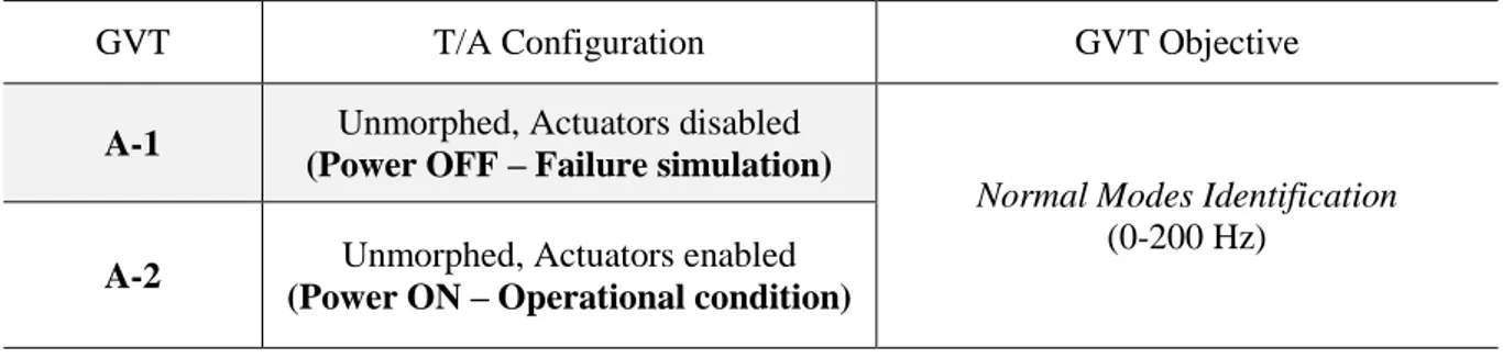
2.4 Experimental activities 24
2.4.1 Functionality tests 25
2.4.2 Ground Resonance Test and FE updating 26
2.5 Actuation performance in Wind Tunnel Test 36
2.6 Conclusions 38
Acknowledgments 38
References 38
3.
Aero-Servo-Elasticity of Electro-Actuated Morphing devices
40
3.1 Introduction 40
3.2 Model Condensation 41
3.3 Aeroelastic Model 43
3.4 Aero-Servo-Elastic stability analysis 46
3.4.1 Anti-symmetric aeroelastic analysis 47
3.4.2 Symmetric aeroelastic analysis 49
3.5 Conclusions 53
Acknowledgments 55
References 55
4.
Electro-Actuation System Strategy for a Morphing Flap
58
4.1 Clean Sky Challenge: JTI and Airgreen 2 frameworks 58
4.2 Robotized system architecture 60
4.2.2 Actuation design 62
4.3 Morphing flap overview 65
4.3.1 Target shapes and specifications 65
4.4 Control Logic Strategy and Lab test on Iron Bird 66
4.4.1 System arrangement 66
4.5 Towards a Multi-Modal Morphing Flap: Clean Sky 2 upgrade 73
4.5.1 Design Loads 75
4.5.2 Actuation Concept Layout and Control Scheme 76 4.5.3 Compatibility with other electric devices 82
4.6 Conclusions and next activities 88
References 88
5.
Self-sensing System for Compliant Morphing Tab
92
5.1 Research scenario 92
5.2 Materials and methods 94
5.3 Characterization of self-sensing resin 94
5.4 Integrated self-sensing coating 100
5.5 Conclusions and outlooks 104
Acknowledgments 104
References 104
4
Foreword
Smart structures, able to sense changes of their own state or variations of the environment they’re in, and capable of intervening in order to improve their performance, find themselves in an ever-increasing use among numerous technology fields, opening new frontiers within advanced structural engineering and materials science. Smart structures represent of course a current challenge for the application on the aircrafts. A morphing structure can be considered as the result of the synergic integration of three main systems: the structural system, based on reliable kinematic mechanisms or on compliant elements enabling the shape modification, the actuation and control systems, characterized by embedded actuators and robust control strategies, and the sensing system, usually involving a network of sensors distributed along the structure to monitor its state parameters. Technologies with ever increasing maturity level are adopted to assure the consolidation of products in line with the aeronautical industry standards and fully compliant with the applicable airworthiness requirements. Until few years ago, morphing wing technology appeared an utopic solution. In the aeronautical field, airworthiness authorities demand a huge process of qualification, standardization, and verification. Essential components of an intelligent structure are sensors and actuators. The actual technological challenge, envisaged in the industrial scenario of “more electric aircraft”, will be to replace the heavy conventional hydraulic actuators with a distributed strategy comprising smaller electro-mechanical actuators. This will bring several benefit at the aircraft level: firstly, fuel savings. Additionally, a full electrical system reduces classical drawbacks of hydraulic systems and overall complexity, yielding also weight and maintenance benefits. At the same time, a morphing structure needs a real-time strain monitoring system: a nano-engineered polymer capable of densely distributed strain sensing can be a suitable solution for this kind of flying systems. Piezoresistive carbon nanotubes can be integrated as thin films coated and integrated with composite to form deformable self-sensing materials. The materials actually become sensors themselves without using external devices, embedded or attached.
This doctoral thesis proposes a multi-disciplinary investigation of the most modern actuation and sensing technologies for variable-shaped devices mainly intended for large commercial aircraft. The personal involvement in several research projects with numerous international partners - during the last three years - allowed for exploiting engineering outcomes in view of potential certification and industrialization of the studied solutions. Moving from a conceptual survey of the smart systems that introduces the idea of adaptive aerodynamic surfaces and main research challenges, the thesis presents (Chapter 1) the current worldwide status of morphing technologies as well as industrial development expectations. The Ph.D. programme falls within the design of some of the most promising and potentially flyable solutions for performance improvement of green regional aircrafts. A camber-morphing aileron and a multi-modal flap are herein analysed and assessed as subcomponents involved for the realization of a morphing wing.
An innovative camber-morphing aileron was proposed in CRIAQ MD0-505, a joint Canadian and Italian research project. Relying upon the experimental evidence within the present research, the issue appeared concerns the critical importance of considering the dynamic modelling of the actuators in the design phase of a smart device. The higher number of actuators involved makes de facto the morphing structure much more complex. In this context (Chapter 2), the action of the actuators has been modelled within the numerical model of the aileron: the comparison between the modal characteristics of numerical predictions and testing activities has shown a high level of correlation.
Morphing structures are characterized by many more degrees of freedom and increased modal density, introducing new paradigms about modelling strategies and aeroelastic approaches. These aspects affect and modify many aspects of the traditional aeronautical engineering process, like simulation activity, design criteria assessment, and interpretation of the dynamic response (Chapter 3). With respect the aforementioned aileron, sensitivity studies were carried out in compliance with EASA airworthiness requirements to evaluate the aero-servo-elastic stability of global system with respect to single and combined failures of the actuators enabling morphing. Moreover, the jamming event, which is one of the
main drawbacks associated with the use of electro-mechanical actuators, has been duly analyzed to observe any dynamic criticalities. Fault & Hazard Analysis (FHA) have been therefore performed as the basis for application of these devices to real aircraft.
Nevertheless, the implementation of an electro-mechanical system implies several challenges related to the integration at aircraft system level:the practical need for real-time monitoring of morphing devices, power absorption levels and dynamic performance under aircraft operating conditions, suggest the use of a ground-based engineering tool, i.e. “iron bird”, for the physical integration of systems. Looking in this perspective, the Chapter 4 deals with the description of an innovative multi-modal flap idealized in the Clean Sky - Joint Technology Initiative research scenario. A distributed gear-drive electro-mechanical actuation has been fully studied and validated by an experimental campaign. Relying upon the experience gained, the encouraging outcomes led to the second stage of the project, Clean Sky 2 - Airgreen 2, encompassing the development of a more robotized flap for next regional aircraft. Numerical and experimental activities have been carried out to support the health management process in order to check the EMAs compatibility with other electrical systems too.
A smart structure as a morphing wing needs an embedded sensing system in order to measure the actual deformation state as well as to “monitor” the structural conditions. A new possible approach in order to have a distributed light-weight system consists in the development of polymer-based materials filled with conductive smart fillers such as carbon nanotubes (CNTs). The thesis ends with a feasibility study about the incorporation of carbon nanomaterials into flexible coatings for composite structures (Chapter 5). Coupons made of MWCNTs embedded in typical aeronautic epoxy formulation were prepared and tested under different conditions in order to better characterize their sensing performance. Strain sensing properties were compared to commercially available strain gages and fiber optics. The results were obtained in the last training year following the involvement of the author in research activities at the University of Salerno and Materials and Structures Centre - University of Bath.
One of the issues for the next developments is to consolidate these novel technologies in the current and future European projects where the smart structures topic is considered as one of the priorities for the new generation aircrafts. It is remarkable that scientists and aeronautical engineers community does not stop trying to create an intelligent machine that is increasingly inspired by nature. The spirit of research, the desire to overcome limits and a little bit of imagination are surely the elements that can guide in achieving such an ambitious goal.
6
1. Introduction to Smart Systems
What does mean smart system?
A structure is smart if it is able to modify its characteristics, adapting itself to the external conditions in which it operates. The term "Intelligent Structure" derives from the idea of integrating active elements into the structure, thanks also to the development of innovative materials, and began to materialize starting from the 90s with the significant scientific activity carried out by researchers such as Crawley, de Luis, Wada and Fanson, [1-2]. It is therefore necessary to monitor the instantaneous “state” variables of the system so that its response can be controlled accordingly: this capability can be implemented by combining a sensory network and actuators, implemented with the minimum level of invasiveness. This last requirement stimulates the search for increasingly advanced structural design concepts based on the "embedded system" design logic, able to manage the infinite degrees of freedom of real structures with the lowest possible number of transducers. Sun J. et al. proposes in [3] a recent review a logical scheme which well describes the smart system concept, Figure 1.1. Smart materials and structures can obtain information from the environment around the skin (sensing), they then produce an internal chemical or physical effect delivered to the brain for decision making (control), and finally, they implement actions through the muscles (actuation). The information passes through the nerves, and each part is linked by tendons and fibrous bands (skeletons).
Figure 1.1. Synoptic layout of the smart structures and materials, [3].
An interesting exposition on the field of smart materials and structures dates back to the 90s thanks to Thompson B.S., Gandhi M.V. and Kasiviswanathan S.. The salient features of this biomimetic eclectic discipline have been highlighted outlining the ramifications on real engineering applications, [4]. Smart structures have demonstrated a broad range of potential applications for performance enhancement of the aerospace industry. Several research and practical applications projects conducted by government agencies, aerospace industries, and universities addressing numerous target applications such as flutter suppression, buffet control, vibro-acoustic control, adaptive structures and self-sensing systems, [5]. The Airbus airframe development strategy is based on the “Airbus Intelligent Airframe” approach, which targets on development and implementation of intelligent solutions and smart structures with intelligent characteristics, Figure 1.2. When evaluating the potential of new structural solutions and new technologies, Airbus has both in mind: the benefit in upgrading existing models and new programmes, [6-7].
(a) Analogy with the human body (b) Intelligent network
Figure 1.2. Airbus challenges: human nervous system based intelligent airframe.
The biomimetic wing concept
Nature is surely the most striking example for the design of a more fascinating idea: in the aeronautical and aerospace scenario, the emulation of the birds’ flight is the true challenge of a morphing wing, Figure 1.3. Morph is a word descending from ancient Greek, μορφή or “morfé,” and indicates shape, figure, or other synonyms, [8]. Therefore, morphing is something related to shaping, the modification of the original aspect of a certain entity. The integration of increasingly innovative technologies as reliable kinematic mechanisms, embedded servo-actuation and smart materials systems, are designed in order to assure new devices, fully compatible with the more and more stringent airworthiness requirements. Over the next few years the aviation industry will face the challenge to develop a new generation of air vehicles characterised by high aerodynamic efficiency and low environmental impact; still, the technologies currently available are inadequate to meet the demanding performance requirements and to comply with the stringent regulations in terms of polluting emissions: each of these reasons could suggest to a company to replace its fleet with new aircrafts. Next generation aircraft requires wings able to reconfigure their self in multiple shapes, in order to be optimal in every specific flight condition and reduce the waste of fuel resulting from a not commensurate flight dynamic.
8
Looking at a generic aircraft morphing architecture, whether designed or realized, it is easy to imagine that the natural evolution of these systems is to expand the deformability regions and increase the macroscopic degrees of freedom of the reference structure. It could be stated that this tendency aims at emulating biological flight (like the bird one) more and more, even trying to move beyond that boundary. From these considerations, aircraft morphing systems can be classified as real Smart Structures as well as suitable candidates as part of a new category of robots, [9]. A robot is a mechanical or virtual artificial agent, as an electro-mechanical machine, driven through the support of devoted computer codes or electronic circuitry. The word is derived from the Czech “robota”, meaning heavy duty, in turn descended from the ecclesiastic Slavic “rabota” meaning servitude or servants. Exoskeletons or anthropomorphic autonomous or remote driven mechanical systems are classical examples of robots. Computer systems should be included in this definition as main elements of the control and sensor systems, including associated data processing and information feedback. Indeed, standard drones, currently available on the mass market, are basic examples of robots. In the actual opinion, morphing systems are to evolve towards machines capable of multiple degrees of freedom that can resemble the behaviour of living flying animals (ornitomorphic), as they move to higher, complex levels. The fact that these systems could be conceived for low to high speeds up to super and hypersonic velocities as well as for space missions, makes the future very close to science fiction. On the other hand, some prototypic versions of these concepts are already available, while a lot of movies try to envision far more prospects. The control systems should govern the behaviour of this futuristic machine, preventing general instabilities or strain excess, while an autonomous system or a human pilot drives it at a macroscopic level. In detail, these innovative concepts are applied to wings, enabling limited changes of their geometry and preserving their capability to bear external and internal loads, Figure 1.4.
(a) Robotic hand (b) Adaptive wing
Figure 1.4. Smart Intelligent Structures: cybernetic analogy.
Smart Intelligent Structures may be introduced if the former concept is combined with recent achievements in information technology, signal processing, and cybernetics. A classical definition of cybernetics comes from N. Wiener, that explained the terms as the “scientific study of control and communication in the animal and the machine” (1948), [10]. The etymology of the word comes from Greek κυβερνητική (kybernetike), meaning governance or guidance. It may be seen as an interdisciplinary matter that links together control systems, electronics and electronic networks, informatics, neuroscience, logics, evolutionary biology and psychology, both human and animal. Autonomous decision-making and experience-based learning capabilities are traditionally linked to the development of information data processing and management systems that are at the base of biomimetic robot intelligence, [11]. Analogously, robotics is the fusion of some specialized mechanic, materials, electric, electronic, systems, and information engineering technology branches, dealing with the design, construction, operation, and application of robots, [12]. The morphing system should be able to deform itself, as it is sufficiently rigid to resist the action of several forces. Of course, these general principles can be specialized in many ways when the real application occurs. A typical scheme of a morphing system may be seen in Figure 1.5, where the main elements are reported with their logical collocation and links.
Figure 1.5. Core components of an adaptive system.
Actuation and sensing integrated systems
A biomimetic system is then imagined, commanded by an artificial or a natural intelligence. These are defined as integrated load-bearing architectures that can adapt themselves to variations of external environments, enlarging their operational domain while maintaining optimal performance levels. Adjustments follow mutated needs and try to maintain the structure into the best possible configuration while new occurrences arise and evolve with time. Such structural systems exhibit additional DOF that allows continuous transformation. Their design does not refer to a single reference point but to an extended domain. Structural kinematic adaptive systems bring important deals with respect to safety, [13]. First of all, because of the higher number of parts, the probability of failure increases for a complex system. A key point is then the capability of reducing the number of parts, classically a good index of the system fragility (or, on the contrary, its inverse is a good measure of the system robustness). Classical kinematic solutions are therefore consolidated on one side and are complex on the other. Fully compliant systems are instead structural components, forced to continuous deformation along an established path by relatively simple actuation architectures.
This philosophy was addressed by the joint teams of Flexsys, NASA, and Gulfstream. It has shown its major disadvantage in being strongly exposed to very severe aeroelastic behaviour by increasing its eigenmodes, [14]. It should also be added that mechanical devices are more rigid and their behaviour is better known in literature and in the aeronautical field, as a simple evolution of the flap, aileron, slat, etc. It is also worthwhile to discuss mass contribution. In principle, it shall be higher for kinematic chains than compliant structures. Still in this condition, the modal density is expected to be larger for the latter than the former, meaning very low rigidity levels for those architectures. This can also be an issue for the static response. Motors themselves are worth some dedicated statements. A kinematic actuation requires distributed active devices to achieve the required performance. A compliant architecture could rely on a smaller number of actuators because the driven structure is conceived as a continuous system. Please note that, the larger the actuators number, generally, the higher the stiffness. Now, from the point of view of maintenance, costs, operability, and hazards, the larger the number of motors, the higher the risk of failure, and the higher the complete system price. It should be added that a system with many devices can sometimes be attributed with a certain level of redundancy and safety (as each component is less significant with respect to the whole).
In any case, the reduction of the installed motors may be a design indication for the future. Generally, from the certification point of view, a kinematic system is more acceptable than a compliant system because it derives from very large experience on similar architectures. In other words, it is already in the forma mentis of the engineers and regulation public officers. Compliant systems have a long way to go before they can be fully accepted. Figure 1.6 shows a practical comparison between the aircraft torque shaft configuration and a distributed actuation arrangement suitable for a morphing trailing edge device.
10
Figure 1.6. Comparison between distributed and concentrated actuation concept.
In the shafted configuration, all actuators are mechanically linked by the torque shaft controlled by the power distribution unit whereas in a distributed arrangement, no more torque shaft is needed. However, the implementation of an electrical system implies many challenges related to the integration at aircraft system level. In particular, it must be demonstrated their reliability in harsh environment, moreover their safety and types of failures with an aim to reconfiguration enhancement.
Driven by the demand to optimize aircraft performance, decrease operating and maintenance costs, increase dispatch reliability, and reduce gas emissions - have underscored the aircraft industry's renewed push toward the concept of more electric aircraft (MEA), and ultimately an all-electric aircraft.
Specifically, the MEA concept provides for the utilization of electric power for all non-propulsive systems. Traditionally these non-propulsive systems are driven by a combination of different secondary power sources such as hydraulic, pneumatic, mechanical and electrical. Recent technological advances in the field of power electronics, fault-tolerant architecture, electro-hydrostatic actuators, flight control systems, high density electric motors, power generation and conversion systems have ushered the era of the MEA. This trend is accelerating, as aircraft OEMs collaborate with their suppliers to design new systems and implement new electrical-intensive architectures. Adoption of the MEA concept is seen as critical enabler for the aircraft industry to unlock significant improvements in terms of aircraft weight, fuel consumption, total life cycle costs, maintainability and aircraft reliability. An advanced high lift actuation system architecture with distributed active controlled flap actuators offers the capability for implementation of additional functionalities for the trailing edge with benefits on aircraft level and improvements at manufacture and assembly level. Thus, the distributed high lift system architecture is to be regarded as an enabler of the above-mentioned benefits, [15-20]. The important consequences in operation and maintenance following the issue of complex actuation networks, are amplified with the implementation of the sensor network, [21].
The high number of DOF, nearly infinite, is an immediate problem to manage when dealing with unconventional systems. A suitable sensor network aimed at monitoring morphing architectures should have a relevant extension and considerable density, suitable of catching the various shapes that are achieved during operation. This fact implies the deployment of a huge quantity of transducers that can reveal needed information on a suitable number of points. Accelerometers are widely used in common practice, both in lab and in flight, but have some features that suggest that other kinds of detection elements should be employed. Generally speaking, strain devices are more appropriate than displacement (velocity, acceleration) sensors because they avoid rigid motion contributions (coming from taxing, maneuver, and so on) that can disturb measurement output. Usually, they are also lighter. Moving from the former to the latter is just a matter of installation. Examples are strain gauges or optical fiber-based devices (Fiber Bragg’s Gratings for instance, FBG), Figure 1.7.
(a) Metallic panel (b) Composite panel
Figure 1.7. Distributed fiber optic sensing.
In recent years, much more attention has been turned to the design of nano filler for polymer materials to harness the exceptional electrical properties of CNTs. In particular, polymers with the incorporation of CNTs show great potential for microelectronic applications such as highly sensitive strain sensors for aeronautical smart systems. For such application, the direct current (DC) properties of nanocomposites are used. Currently, numerous experimental studies aimed to well characterize the electrical properties of nanocomposites, made from insulating polymers filled by CNTs, are being carried out. In this work, the research has been focus on assessing the resistivity properties of nanocomposites for potential aeronautical applications and in particular for smart structures. An intelligent structure must be able to measure in real time its deformation state: the example of a morphing wing is certainly useful to understand the ambitious realization of a sensing system for detecting strain variations under the action of the external load. Polymer-based composite materials belong to the family of ultra-light structural materials, which have been introduced massively in the recent years in aeronautical applications, but also in other fields like civil and automotive engineering as well. Moreover, the anisotropy of the elastic properties allows optimizing the performance of the structural materials, offering countless new design possibilities. Non-destructive testing and surveillance techniques have been developed over the years, mainly encouraged by the constant search of enhanced safety in the aeronautical industry and in civil engineering applications. However, the standard methods currently used are far from being optimal for these novel materials, and potential improvements in the continuous monitoring techniques are constantly being investigated. From this perspective, new Structural Health Monitoring (SHM) systems have thus emerged during the last years as an interesting option.To meet the demand, especially of the aerospace field, of more and more advanced materials, more intense studies are being carried out on carbon-fiber reinforced composite materials. CNTs reinforcements allow for modulating the characteristics of a polymer matrix composite making it also suitable for more extreme operating conditions and resistant to environmental damage. The advantages of carbon nanotube reinforcement are many. They allow to improve the mechanical characteristics of the composite. The most relevant aspect, however, lies in the electrical properties that make these composites suitable for the design of self-sensing materials. In other words, composite materials reinforced with CNTs are used as sensors as well as structural materials and this is a highly sought after goal in recent times. Electrical techniques are the non-destructive way to monitor damage in composites subjected to static and dynamic loads. However, this approach is not applicable to composites where the fibers are non-conductive, such as glass and aramid fibers. Damage detection through conductivity measurements offers many advantages when compared to traditional glass fiber optic sensors. In fact, because of their high cost, it is not possible to create a dense network of these fibers to inspect large parts of the composite and especially if the damage spreads in the material without crossing the fiber could also not be detected. Therefore, the reinforcement with carbon nanotubes is the among best candidates to go under the many aspects described.
12
Figure 1.8. Smart sensing for adaptive wings, [21].
A successful development of nanotechnology and its implementation attracted the attention within several NASA missions. NASA's Langley Research Center explored the real feasibility to embed CNT-based sensors in structures of all geometries to monitor conditions both inside and at the surface of the structure to continuously sense changes. Global, real-time structural health monitoring systems for air and space vehicles require new strategies for the development of extremely small and lightweight sensors that are embeddable and scalable to arrays. Geometries with very thin regions (e.g., leading edges), sharp changes (e.g., wing/fuselage junctions) or areas of extremely high curvature are often impossible to instrument. NASA solves this issue with a flexible CNT-based structural health monitoring sensor for measuring the induced strain, pressure, and temperature both within and at the surface of a structure--an attractive candidate for smart skin technologies, [22-25]. The sensing capabilities of mechanical stress and strain for the SWCNT/polyimide nanocomposite were demonstrated via piezoelectric, piezoresistance and piezocapacitance response.
Towards the ready-to-fly intelligent systems
The interest toward the environmental impact of transports is gaining more and more attention, due to the various consequences it entails, such as climate changes. Inside the European Community, the ACARE reports some data, [26], regarding air transport contribution to climate change which represents 2% of the total CO2 emissions (and the 12% of all transport sources). The objectives of the next twenty years regard a more environmental-friendly approach to the design and management of the aircraft, generally referred to a substantial reduction in emissions, both chemical and acoustic, and a reduction in consumption. These macro objectives are converted into many research topics including the development of innovative architectures able to optimize the configuration of the aircraft in various flight conditions, or able to adapt in the various phases of the mission. Significant improvements can be achieved by the implementation of novel configurations (shapes and architectural layout), propulsion systems improvement, integrated optimization and drag reduction, [27]. The design and optimization of high lift systems is one of the most complex task in aircraft design. It involves a close combination of aerodynamics, structures and kinematics. The evolutionary trend of the High-Lift Devices has been strongly driven by the dramatic improvement in aerodynamic tools for optimization, [28], and structural computational systems like elastic and rigid multi-body coupling simulations. Through this approach, satisfactory performance were attained with penalties in structural complexity and weight and therefore in costs. Later on, computational fluid dynamics (CFD) improvements permitted optimizing flap systems in 2D flow with a clear advantage for Fowler mechanisms that allowed reaching higher values of maximum lift, [29]. Such devices, on the other side, required even more complex kinematic actuation systems. Those flap systems used in fact massive mechanisms made of linear or curved tracks (translation) in conjunction with revolute joints (rotation), leading to significant weight penalties. The high weight drawbacks were principally due to the incidence of the aerodynamic loads, requiring stiff kinematic structures. High performance (𝐶𝐿𝑚𝑎𝑥) was achieved by means of
multi-Flexible skin
slotted bi-dimensional flap design and experimental validation, [30]. Aircraft producers have participated for a long time to incorporate innovative technologies into their design process to attain innovative concepts for conventional structures. Among these concept, variable camber LE and TE, as depicted in Figure 1.9. In recent times, this target has been referred to as the development of “Morphing Wing Technology”, [31-32].
Figure 1.9. Variable camber LE and TE on an aircraft wing, [30].
The idea of changing the wing shape or geometry starts form the “inspiration from nature”. Early design is covered extensively in [33]. Compliant, variable camber devices appeared in a number of countries, as evidenced by the wide variety of patents issued in Great Britain, Germany and the United States. Otto Schmidt patented a variable camber device in Germany in 1895, Figure 1.10(a), [34]. The Wright brothers built the first heavier- than-air aircraft with engine with a twisted wing for roll control. Holle and Judge patented a variable camber device in Great Britain in 1917, Figure 1.10(b), [35] and Parker in 1920 in USA, Figure 1.11, [36].
(a) (b)
14
Figure 1.11. Parker morphing rib design, [36].
It is then noticeable that variable camber devices have been studied and investigated for long times, but only in recent year they found a practical application. Both in military (F-111 experiment, [37] and commercial aviation (FlexSys flight test, [38]), morphing is turning into a breakthrough technology. In light of those successful developments, also in Europe, many research project were launched in order to develop innovative aircraft structure based on morphing devices. Among these, the most important research activities are SARISTU, [39], and CleanSky, [40], projects. In the framework of SARISTU project, a full-scale wing prototype equipped with three morphing architectures (trailing edge, leading edge and winglet) was developed and tested in wind tunnel, [41]. The design of the morphing trailing edge is widely described in [42]. The research project CRIAQ-MDO505, born by an intense Canadian and Italian synergy comprising industries, research centers and universities has allowed for investigating morphing structures potentials through the design and manufacturing of a variable camber aileron tailored for new regional aircrafts, [32]. In the Clean Sky scenario, an innovative flap morphing full-scale prototype has been realized for application on next generation green regional aircraft (CS-25 category). The first studies were limited to a portion of the flap element, [43], and then extended to a full-scale prototype as described in [44-45].
Aims of the thesis
The work discussed in this manuscript was developed as part of international collaborations and the personal contribution was specifically aimed at the design of the actuation, control and sensing systems for adaptive structures. The demand for augmented functionality, inevitably leads to more complex design arrangements which require a fully transversal and multi-disciplinary design approach: aeronautical sciences, robotics, biomechanics concepts must converge to a single technically satisfactory outcome.The focus activity of the doctorate was placed within the European Project Clean Sky 2, oriented towards the executive development of a multi-functional morphing flap for the next generation regional aircraft. Anyway, the scientific surveys were carried out on experimental platforms already available at the Smart Structures Lab (University of Naples “Federico II” – Aerospace Section). In such a way, different actuation and control strategies were investigated in order to face the greater complexity represented by the morphing flap end application. Numerical and experimental methods have been implemented looking always at the potential industrialization of these flyable solutions, meeting so the compliance with the current airworthiness requirements. The logical-temporal flow of the activities is schematized in the Figure 1.12. The overall research trend pursued by the author is in full agreement with the current needs for a “more electrical aircraft”. Design methodologies of robotic systems based on EMAs and distributed sensors have been carefully implemented to define systems with multiple degrees of freedom. The solving approach has been structured on several key aspects, but all interconnected to guarantee finally a robust system. The research path took place with investigations for the validation of the motion system of a camber-morphing aileron within the Italian-Canadian collaboration (CRIAQ-MDO505). The author's work has been encompassed in the design and modelling activities, contributing to a better identification of the dynamic effect (elasticity, damping and mass) of the actuators on the overall response of the system. Experimental evidence allowed to validate the approaches adopted (Chapter 2). Furthermore, rational approaches have been performed forecasting the impact of a distributed actuation system on the whole aircraft. Effects of aero-servo-elastic
instability as well as critical scenarios (failure and jamming of actuators) have been extensively studied with reference to reliability issues (Chapter 3). The results achieved on a small platform (morphing aileron) have been duly extended to the flap region. As part of the Clean Sky framework, an innovative actuation system has been developed that comprises electro-mechanical modules. A challenging key aspect was the ability to get and preserve desired target wing shapes within a certain tolerance, allowing optimal aerodynamic performance in operative conditions and loads. In the Chapter 4, the strategies followed to define the electro-actuation and control system of a morphing flap have been therefore outlined with emphasis on both numerically and experimental methodologies that have been implemented. The design choices were also conditioned by the presence of other devices that further complicate the layout of the flap. It was in fact envisaged that the final device will be equipped with plasma synthetic jets (PSJ) for the optimization of the aerodynamic performances. The operation of these devices could represent a possible source of disturbance for the control system conceived. Electro-magnetic interferences of the actuators with the other electronic equipment of the flap have been assessed according to EMC (Electro-Magnetic Compatibility) specification, crucial for the safety of modern electric aircraft. The additional operative modes of morphing flap consist in symmetrically deflecting and twisting the tab segment: it is supposed to be activated in cruise condition only, when the flap is stowed in the wing. Because of the progress in research of advanced composites, flexible wing parts are maturing and becoming more attractive for application in the aviation industry. In the particular case of the morphing tab, the possibility of developing a single compliant composite segment is being analysed. The author has investigated a potential sensing system useful for identifying the structural deformation state when the external skin could be stretched under the aerodynamic load (Chapter 5). The main steps of the activities related to each project are summarized in the Table 1.1.
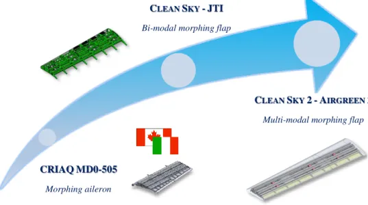
Figure 1.12. Ph.D. Research International Framework. Table 1.1. Summary of Ph.D. Research activities.
CRIAQ MD0-505
Morphing Aileron
Dynamic modelling of actuators Aero-servo-elastic effects of actuators Numerical-experimental correlation Validation of actuation performancs
Clean Sky - JTI
Bi-Modal Morphing Flap
Distributed actuation design Control logic implementation
Experimental activities on an «iron bird»
Clean Sky 2 - Airgreen 2
Multi-Modal Morphing Flap
Distributed actuation design Control logic strategy
EMC analysis with PSJ system Integrated sensing system design
CRIAQMD0-505
Morphing aileron
CLEAN SKY -JTI
Bi-modal morphing flap
CLEAN SKY 2-AIRGREEN 2
16
References
[1] Crawley, E.F. and de Luis, J.: Piezoelectric actuators as elements of intelligent structures, AIAA Journal 25(10), 327–343 (1987).
[2] Wada, B.K., Fanson, J.L. and Crawley, E.F.: Adaptive structures, Journal of Intelligent Material Systems and Structures 1(2), 157–174 (1990).
[3] Sun, J., Guan, Q., Liu, Y. and Leng, J.: Morphing aircraft based on smart materials and structures: A state-of-the-art review, Journal of Intelligent Material Systems and Structures 27(17), 2289–2312 (2016). [4] Thompson B.S., Gandhi M.V. and Kasiviswanathan S.: An introduction to smart materials and structures,
Materials & Design 13(1), 1–9 (1992).
[5] Yousefi-Koma, A. and Zimcik, D.G.: Applications of Smart Structures to Aircraft for Performance Enhancement, Canadian Aeronautics and Space Journal 49(4), 163–172 (2003).
[6] Speckmann, H.: Structural Health Monitoring with Smart Sensors Approach to a New NDI Method, Proc. SPIE Conference on Smart Structures and Materials and NDE for Health Monitoring and Diagnostics, 17- 21 March 2002, San Diego, California.
[7] Speckmann, H.: Structural Health Monitoring (SHM): One Technology of the Airbus Intelligent-Airframe philosophy, Proc. Of the Asia-Pacific Workshop of Structural Health Monitoring Yokoama/Japan (Ed.: A. Mita).
[8] Concilio, A. and Lecce, L.: Morphing Wing Technologies Large Commercial Aircraft and Civil Helicopters, Historical Background and Current Scenario (Elsevier Book), 3–84 (2018).
[9] Srinivasan, A.V. and McFarland, D.M.: Smart Structures: Analysis and Design, Cambridge University Press, Cambridge (2001).
[10] Wiener, N.: Cybernetics or Control and Communication in the Animal and the Machine, The MIT Press, Cambridge, MA, ISBN 978-0-262-73009-9 (1961).
[11] Kim, J. H., Matson, E. T., Myung, H. and Xu P. (eds): Robot Intelligence Technology and Applications 2012 - An Edition of the Presented Papers from the 1st International Conference on Robot Intelligence Technology and Applications, Springer Science & Business Media, Berlin Heidelberg, ISBN 978-3-642-37374-9 (2013). [12] Kalkan, S., IEEE Staff (ed): 2015 International Conference on Advanced Robotics (ICAR), IEEE Publishing,
New York, NY, ISBN 978-1-467-37510-8 (2015).
[13] Rushby, J.: A safety-case approach for certifying adaptive systems, AIAA Infotech@Aerospace Conference, Seattle, WA, April 6-9 (2009).
[14] Herrera, C. Y., Lung, S. F., Ervin, G. and Flick, P.: Aeroelastic airworthiness assessment of the adaptive compliant trailing edge flaps, 46th International Symposium of the Society of Flight Test Engineers, Lancaster, CA, September 14-17 (2015).
[15] Wheeler, P. and Bozhko, S.: The More Electric Aircraft: Technology and challenges, IEEE Electrification Magazine, 2(4), 6–12 (2014).
[16] Sarlioglu, B. and Morris, C.T.: More Electric Aircraft: Review, Challenges, and Opportunities for Commercial Transport Aircraft, IEEE Transactions on Transportation Electrification, 1(1), 54–64 (2015). [17] Wheeler, P.W., Clare, J.C., Trentin, A. and Bozhko, S.: An overview of the more electrical aircraft, 227(4),
578–585 (2012).
[18] Castellini, L., D’Andrea, M. and Borgarelli, N.: Analysis and design of a linear electro-mechanical actuator for a high lift system, In: 2014 international symposium on power electronics, electrical drives, automation and motion, Ischia, Italy, 18-20 June 2014, 243–247.
[19] Bennett, J. W.: Fault Tolerant Electromechanical Actuators for Aircraft, Ph. D. thesis, Newcastle University (2010).
[20] Qiao, G., Liu, G., Shi, Z., Wang, Y., Ma, S. and Lim, T.C.: A review of electromechanical actuators for More/All Electric aircraft systems, Proc IMechE Part C: J Mechanical Engineering Science, 232(22), 4128– 4151 (2018).
[21] Mukhopadhyay, S.C. (Ed.): New Developments in Sensing Technology for Structural Health Monitoring, Lecture Notes in Electrical Engineering, Springer-Verlag, Berlin, Heidelberg, ISBN 978-3-642-21099-0 (2011).
[22] Viscardi, M., Arena, M., Barra, G., Vertuccio, L., Ciminello, M. and Guadagno, L.: Piezoresistive strain sensing of carbon nanotubes-based composite skin for aeronautical morphing structures, Proc. SPIE 10599, Nondestructive Characterization and Monitoring of Advanced Materials, Aerospace, Civil Infrastructure, and Transportation XII, 105991C (2018).
[23] Trigweil, S., Snyderl, S., Hatfield, W., Dervishi, E. and Biris, A. S.: Carbon nanotube coatings as used in strain sensors for composite tanks, NASA Technical Report (2011).
[24] Kang, J.H., Sauti, G., Park, C., Scholl, J.A., Lowther, S.E. and Harrison, J.S.: Carbon Nanotube/Polymer Nanocomposites Flexible Stress and Strain Sensors. Symposium M: Materials and Technology for Flexible, Conformable, and Stretchable Sensors and Transistors MRS Spring Meeting (2008).
[25] Samareh, J.A. and Siochi, E.J.: Systems analysis of carbon nanotubes: opportunities and challenges for space applications, Nanotechnology 28(37) (2017).
[26] ACARE official site: http://www.acare4europe.com/
[27] Goldhammer, M.: The Next Decade in Commercial Aircraft Aerodynamics – A Boeing Perspective, ROI 2009-0501-1167, Aerodays March 2011, Madrid (Spain).
[28] Strüber, H.: The Aerodynamic Design of the A350 XWB-900 High Lift System, proceeding of ICAS 2014, St. Petersburg, Russia, 7-12 September (2014).
[29] Rudolph, P.K.C.: High Lift Systems on Commercial Subsonic Airliners, NASA Contractor Report 4746, September (1996).
[30] Reckzeh, D.: Flying Community Friendly – The Role of High-Lift Aerodynamics, Design concepts & solution for the future, KATnet II conference 2009, Bremen (Germany).
[31] Peter, F. and Stumpf, E.: Morphing Wing Technologies Large Commercial Aircraft and Civil Helicopters – The Development of Morphing Aircraft Benefit Assessment, 103-121, Elsevier Book (2018).
[32] Amendola, G., Dimino, I., Concilio, A., Pecora, R., Amoroso, F. and Arena, M.: Morphing Wing Technologies Large Commercial Aircraft and Civil Helicopters – Morphing Aileron, 547–582, Elsevier Book (2018).
[33] Wagg, D., Bond, I., Weaver, P., and Friswell, M.: Chapter Four: Lightweight Shape-Adaptable Airfoils: A New Challenge for and Old Dream, Adaptive Structures: Engineering Applications, edited by Campanile, L.F., Wiley, New York, 89–129 (2007).
[34] Schmidt, O.: Steuerapparat fur Flugmaschinen, Schmidt Patent No. 84532 (1895). [35] Holle, A.A., and Judge, A.W., U.K. Patent No. 103400, 25 Jan. (1917).
[36] Parker, H.F., The Parker Variable Camber Wing, NACA Fifth Annual Rept. 77 (1920).
[37] F-111 Mission Adaptive Wing, Advanced Fighter Technology Integration, NASA CP-3055 (1990). [38] FlexSys Technology Fact Sheets: www.flxsys.com.
[39] Official site of SARISTU consortium: www.saristu.eu.
[40] Official site of Clean Sky consortium: http://www.cleansky.eu.
[41] Pecora, R., Concilio, A., Dimino, I., Amoroso, F. and Ciminello, M.: Structural Design of an Adaptive Wing Trailing Edge for Enhanced Cruise Performance, 24th AIAA/AHS Adaptive Structures Conference, AIAA SciTech, 4-8 Jan (2016).
[42] Pecora, R., Amoroso, F., Magnifico, M., Dimino, I. and Concilio, A.: KRISTINA: Kinematic Rib based Structural system for Innovative Adaptive trailing edge, SPIE Smart Structures/NDE, Las Vegas, Nevada (USA) March 2016. Proc. SPIE 9801, Industrial and Commercial Applications of Smart Structures Technologies 2016, 980107 (2016); 10.1117/12.2218516.
[43] Pecora, R., Amoroso, F., Amendola, G. and Concilio, A.: Validation of a smart structural concept for wing-flap camber morphing, Smart Structures and Systems, 14(4), 659–679, October (2014);
http://dx.doi.org/10.12989/sss.2014.14.4.659.
[44] Pecora, R., Amoroso, F. and Magnifico, M.: Toward the bi-modal camber morphing of large aircraft wing flaps: The CleanSky experience, Proc. SPIE 9801, Industrial and Commercial Applications of Smart Structures Technologies 2016, 980106 (2016); 10.1117/12.2218415.
[45] Pecora, R., Amoroso, F., Arena, M., Noviello, M.C., and Rea, F.: Experimental validation of a true-scale morphing flap for large civil aircraft applications, Proceedings Volume 10166, Industrial and Commercial Applications of Smart Structures Technologies 2017; 101660L (2017); https://doi.org/10.1117/12.2259878. Awards
[1] May 2015 Award: “Premio Venezia,” Category “Scientific and Academic” for the CRIAQ MDO 505 project, “Morphing Architectures and Related Technologies for Wing Efficiency Improvement”
http://www.italchamber.qc.ca/fr/documents/programme2015.pdf.
[2] April 2016, Morphing Flap Project, Nomination for the Best Clean Sky Project Award in 2016.
[3] July 2017, Best Oral Presentation Award, The 2nd International Conference on Energy Engineering and Smart Materials, ICEESM 2017, Lyon, France, July 7-9, 2017.
18
2. Dynamic Modelling of Electro-Mechanical Actuation
The research project CRIAQ-MDO505, Canadian-European cooperation project on smart technologies, has investigated morphing structures potential through the design and the manufacturing of a variable camber aileron tailored to CS-25 category aircraft applications. The ailerons typically constitute crucial elements for the aerodynamic forces equilibrium of the wing. Therefore, compared to the traditional architectures, the need of studying the dynamic performance is, in the specific case of servo-actuated variable-shaped systems, higher. Relying upon the experimental evidence within the present research, the issue appeared concerns the critical importance of considering the dynamic modelling of the actuators in the design phase of a smart device. The higher number of actuators involved makes de facto the morphing structure much more complex. In this context, the action of the actuators has been modelled within the numerical model of the aileron: the comparison between the modal characteristics of numerical predictions and testing activities has shown a high level of correlation. Moreover, the compliance of the device with the design morphing shapes has been proved by wind tunnel test. The outcomes are expected to be key insights for future designers to better comprehend the dynamic response of a morphing aileron, primary knowledge for safety analyses.2.1
Framework
Nowadays, in the international greening research framework, the morphing technology is playing an important role among the smart structures for the many benefits concerning the reduction of the fuel burn and noise emitted. Adaptive structures may in fact contribute to a significant improvement of the aerodynamic and structural performance over conventional architectures. Morphing research projects will revolutionize the costs of building and operating aircraft. Research team had the interest to verify the applicability of those concepts to the aileron region in order to understand the applicability of the morphing technology while preserving the standard functionality of the control surface. In fact, the aileron zone is very complex from the aeroelastic point of view because instability events, due to the reduced stiffness and the complex aerodynamic field. In addition, the aileron constitutes a primary control surface which failure can be dramatic for the aircraft safety. On the other side, this zone showed the better potentialities for the implementation of the adaptive devices. A morphing aileron adds new functionalities to classical aircraft systems. While keeping its classical function (roll, manoeuvre), it implements camber morphing during cruise, to accomplish aircraft weight variations following fuel consumption or to redistribute span-wise loads to reduce the Root Bending Moment (RBM). It was developed inside the research project CRIAQ-MDO505, a cooperation between Italian and Canadian teams, [1-2]. The objective of that research was to design, manufacture and test in wind tunnel conditions, a smart wing section of a CS-25 aircraft, (Figure 2.1(a)) made of an adaptive box with flexible skin (conceived, designed and developed by the Canadian team) and a morphing aileron (Figure 2.1(b)).
(a) (b)
Figure 2.1. A schematic view of the reference wing (a) and the developed morphing devices (b), CRIAQ-MDO505
Due to the particular unconventional design of the aileron, the author focused on carrying out several experimental activities addressed to substantiate the design strategies. For its greater complexity, a more “robotized” structure requires an even more in-depth study compared to a classical configuration. The effect of the actuation systems is certainly an example parameter to be duly taken into account during the design and verification phases. Changes in dynamic characteristics such as modal mass, stiffness and damping following the actuators activation can influence, also significantly, the dynamic response of an adaptive system. In literature there are just few references regarding the vibrational behavior of a multi-actuated morphing wing. A first investigation was conducted by H. Yuanyuan and G. Shijun in [3] to model and evaluate a morphing wing with an innovative actuation system integrated into the seamless control surface. Vibration tests were performed to validate the first three elastic modes (first two flexional and torsional). Several papers were instead published with regards to the design of actuation systems and their respective control laws. A general algorithm was developed by Austin et al. for static shape control of structures with internal actuators. The shape-control theoretical method was validated by tests conducted on a real model, [4]. Studies for optimal placement of the actuators with a focus on activities aimed at practical implementation were presented in a review, [5]. The design, simulation, and control of the miniature linear actuator used in the actuation mechanism of the morphing wing was presented in [6]. The same authors studied in addition two control methods for obtaining optimized airfoil configurations for fixed wind flow conditions. Both CFD simulations and wind tunnel tests results were combined, [7]. The main purpose of the present work is to identify the modal behavior of the morphing aileron with particular regard to the influence of servo-actuators on the global response. Vibration analyses highlighted an interesting result about the morphing mode shape, which characterize the adaptive wings. It should be theoretically a rigid mode having so a null natural frequency. Nevertheless, the experimental activities have shown that this particular frequency is much higher and increases of about 20% when the actuators are fully activated. This outcome required that this aspect must be taken into account within the numerical modelling phase of the system then an engineering-based method to simulate the effect of the actuators was developed by the author in this chapter. The validated model representative of the fully operative condition (actuators activated) will be then matched with the aircraft aeroelastic scheme for future flutter analyses with respect to relevant operative configurations. Furthermore, the robustness of the adopted mass balancing as well as the persistence of the flutter clearance in case of relevant failures/malfunctions of the morphing system components will be proved according to EASA CS-25 regulations, [8]. The present scenario shows the main results arising in the final phase of the morphing aileron design. All the lab tests were preparatory for the wind tunnel campaign. The chapter presents finally the experimental campaigns conducted in wind tunnel, aimed at correlating the morphing shapes under external load as well as to evaluate the aerodynamic performance of the aileron. The data therefore clarifies the good geometrical correlation between the target analytical shapes and the wind tunnel actual shapes. The effects induced by the technology at aircraft level will be then analyzed in perspective of potential certification and industrialization processes.
2.2
Reference Aileron System
Aileron morphing shapes
The design of a morphing aileron and hence, more in general, of an adaptive device, starts form the definition of the external aerodynamic shapes. They include the baseline and the two morphed configurations (up and down). The shapes are computed on the base of an aerodynamic optimization procedure with the objective to delay transition from laminar to turbulent flow, [9]. Such target contours should be matched by a proper internal structural configuration (rigid-mechanism or compliant) under the effects of the external loads. In fact, the aileron is based on a tailored kinematics driven by an appropriate actuation system in accordance with structural constraints such as:
aileron tip deflection, computed as the angle between the original and the modified chord, fixed in the design range [-7°; +7°];
continuous monotonic curvature of the morphed camber lines (no changes in the sign of the slope of aileron camber);
20
In accordance with the specifications, the aileron main hinge axis remains unmodified and it is located at 70% of the chord as typical position for a 78-seats regional aircraft which is the reference plane of such device. In Figure 2.2 is depicted the aileron trailing edge segment, from 70% to tip, for all the target configurations.
Figure 2.2. Morphing aileron aerodynamic shapes.
The adaptive rib
The proposed aileron rib architecture was based on the well-known finger-like mechanism properly tailored to enable camber morphing. The rib mechanism uses a three segment polygonal line to approximate the camber of the airfoil and to morph it into the desired configuration while keeping practically unchanged the airfoil thickness distribution. Each rib was assumed to be segmented into three consecutive blocks (B0, B1, B2, Figure 2.3(a)) connected by means of hinges located on the airfoil camber line (A, B), Figure 2.3(b). The rib structure is a multi-degree-of-freedom mechanism where each block can be moved by a dedicated actuator. However, it is not feasible to have two drivers for each rib, because of the clear drawback in terms of excessive weight and number of components with significant impact on the maintenance and the reliability. B0 and B2 are then connected through a namely rigid linking rod element (L, Figure 2.3(a)) which reduce the kinematics to an SDOF system. The actuator must supply the required torque (or force) necessary to equilibrate the aerodynamic moment and also to surmount external load in order to move in morphed up and down the aileron ribs.
(a) (b)
Skin
For typical camber morphing applications, it is necessary to substitute the conventional skin with a flexible one, adequately deformable along the longitudinal direction to allow structural shape change and on the contrary, robust enough in the traverse path to withstand aerodynamic pressure. In literature, many design solutions can be found, based on innovative materials such polymeric foams or flexible matrix composites, [10-12]. Inside the SARISTU project, in particular, a skin was proposed, made of a sequence of flexible and stiff segments, covered with adhesive silicone layer used to protect the system and guarantee a certain continuity among foam and aluminum parts. The skin design results truly dependent on the target application; for the aileron, an intermediate design between conventional and innovative skin was developed. A multi-module skin was considered (Figure 2.4, conformal to the multi-box segmentation: in detail, the three blocks were covered with a standard aluminum skin. They were shaped in such a way to reduce the gaps at a minimum and to rotate with respect to each other like sequential meniscuses. Airflow leakage at the segments interfaces was minimized through low-friction silicone seals. However, the segmented skin dynamics does not provide a significant impact over the aileron torsional stiffness; actually, the torsional frequencies between a conventional single-layer skin and a multi-block solution, have been numerically compared by the author on the same reference model. The natural frequency of the observed mode, assuming an alloy single skin, resulted slightly higher than a segmented one, by 14%. In any case, such vibration frequency does not represent a risk for the aeroelastic stability of a potential vehicle, being at the borderline of the [0; 60 Hz] spectral range, generally adopted within flutter investigations for CS-25 aircraft category.
Figure 2.4. Morphing Aileron CAD with detail on the Aluminum skin segments and silicone seals.
The actuation system
The aileron was then equipped with a dedicated and self-contained actuation system. Due to the very small thickness, only two bays were actuated; the others moved as constrained to the second bay actuator, (slave ribs). The conceptual scheme of the actuation system was widely discussed in [11], both analytically and numerically. In synthesis, it is based on a “direct-drive” oscillating glyph mechanism which components are recapped in Figure 2.5 below.
22
Many types of linear guides may be found on the market, on the base of maximum allowable load, mass, sliding mechanism characteristics, overall dimensions, etc. Due to the aileron limited room, only miniaturized linear guides were taken into account in a sort of inverse design process. In fact, at first, size requirements were satisfied in order to avoid any interference with the upper and lower skins during the system operation. Considering actuator specs and individual performances, the Bental RSA-06 actuator has been selected due to its contained weight (less than 0.5 Kg) and dimensions with respect to the other candidates that satisfy the same specifications (Torque: 6.5 Nm, Operating Voltage: 28 V DC).
Overview of the integrated aileron
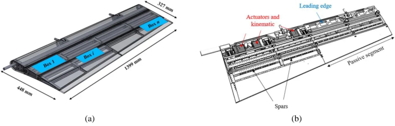
The aileron structural components have been integrated; in fact, ribs are connected by means of a multi-box arrangement, as shown in Figure 2.6. The main geometrical dimensions are herein also reported. The multi-box configuration consists of connecting each span-wise rib with longitudinal stiffeners, namely called spars or stringers, in order to create a closed box as indicated in Figure 2.6(a). The mechanics was designed for synchronous actuation, i.e. no differential motion is namely allowed for consecutive chord-wise segments even if a non-synchronous actuation (structural torsion) could bring to interesting benefits, like the capability of modulating the span-wise load; however, several other issues should have been considered. For instance, the necessity of giving some more degrees of freedom, longitudinally, would have brought to a less stiff architecture, with consequent limits in absorbing external loads. The aileron airfoil maximum thickness percentage is 15% representative of 66 mm at root section and 49 mm at tip. Such tiny dimensions drive the design of the kinematic because the actuators and leverages must be contained into the aileron shape without any structural interferences during morphing. For this reason, it has been difficult to actuate each ribs due to restricted space, in fact the last part of the aileron, as indicated in Figure 2.6(b), are considered passive and its movement is driven by the active segment. Such a passive region is bounded by deformable, non-actuated ribs and is detached from the remaining part of the wing. In synthesis, three actuator systems were deployed on the structure, one for each of the first three ribs towards the wing root. The other two ribs are moved by the third, inner actuator. This device absorbs therefore by itself the incoming load on the external bay.
(a) (b)
Figure 2.6. Morphing aileron structure: multi-box arrangement (a) and internal layout (b). 2.3 Finite Element Model description
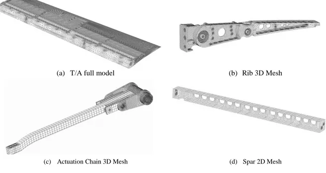
In order to verify the modal behavior of the referred morphing architecture and to correlate the experimental data, a very refined finite element model was carried out. The structural model has been realized with one dimensional (crod and cbush), plane (cquad) and solid (ctetra) finite elements, [14]. Figure 2.7 shows the aileron finite element model. Two-dimensional mesh was used to model spars, skin and trailing edge, while, on the other hand, aileron ribs were modelled with three-dimensional finite elements.
(a) T/A full model (b) Rib 3D Mesh
(c) Actuation Chain 3D Mesh (d) Spar 2D Mesh
Figure 2.7. Morphing aileron, finite element model.
The link between rib block 0 and 2, which essentially absorbs normal stress, can be modelled with a 1D
crod connected to the corresponding rib through cbeam with pin flags imposed at the end-nodes of such
elements to allow the relative rotation between the connecting items, Figure 2.8. For each fastener or screw hole, a master node was generated at the centre and connected to all the nodes on the edge by a RBE2 element. The fastener was then modelled with a spring, namely a cbush element, joining the master nodes at the centre of each hole.
Figure 2.8. Hinge simulation and fastener modelling.
Table 2.1 reports the main characteristics of the model. The current finite element model consists of a high number of nodes and elements, properly necessary to best fit the aileron geometrical CAD. Notwithstanding
24
the forgoing considerations, the same model is also addressed to estimate the dynamic behavior of the aileron in terms of normal modes.
Table 2.1. FEM characteristics.
FE Entity N°
Nodes 567237
RBE2 (Rigid Beam Element Type N.2) 1354 CTETRA (Connection Tetrahedral Element):
• Ribs & Leading edge 440043 CHEXA (Connection Hexahedral Element):
• Actuation chain 89748 CQUAD (Connection Quadrilateral Element):
• Skin, trailing edge 149117 CBAR (Connection Bar):
• Fasteners, Pin 1019
All the components of the morphing aileron, apart from the steel links, are made of aluminium (Type code Al2024-T351). Therefore, this was the material assigned to all the elements. The materials properties are listed in Table 2.2. In particular, as first way to verify the numerical model consistency, the global structural mass of the aileron FE model was estimated around 19 kg (about 10 kg for the only leading edge) which is close to the value of 19.2 kg of the weighted manufactured prototype. This measure is coherent with the fact that rivets and other joints were not considered in the computation. In this analysis, targeting the tests in WT on a very rigid structure, this variation was not considered important. On the other side, modal analysis, static response, and dynamic response did match well the experimental results. If a flyable or more compliant demonstrator (for instance, an aileron deployed on a long-span wing), these contributions should be evidently taken into account.
Table 2.2. Aileron materials.
Material E [GPa] [𝐤𝐠/𝐦𝟑] Items
Steel C50 220 7850 0.3
Actuation system beam; Linear guide features;
crank and rib links
Al 2024-T351 70 2768 0.33 All other items
2.4 Experimental activities
A prototype of the aileron was manufactured and tested for the experimental campaign before the wind tunnel assessment. The lab tests were aimed at:
demonstrating the morphing capability of the conceived structural layout by means of its functionality;
![Figure 1.10. An earlier concept of control surface (a), [34], and a variable camber device (b), [35].](https://thumb-eu.123doks.com/thumbv2/123dokorg/2755310.881/13.892.110.765.787.985/figure-earlier-concept-control-surface-variable-camber-device.webp)